Mitsubishi Air Lubrication System
http://www.gizmag.com/mitsubishi-air-lubrication-system/21196/
January 23, 2012

In February last year, Mitsubishi Heavy Industries (MHI) and transport company Nippon Yusen Kaisha (NYK) announced plans to investigate the effectiveness of a system intended to reduce the frictional resistance between a vessel's bottom and the seawater using a layer of air bubbles. Now MHI has coupled the Mitsubishi Air Lubrication System (MALS) with a high-efficiency ship hull in the conceptual design for a container ship that the company claims would offer a reduction in CO2 emissions of 35 percent compared to conventional container carrier designs.
To verify the CO2 reduction efficiency of MALS, MHI has installed it on the "YAMATAI," a module carrier operated by an NYK subsidiary. A module carrier was chosen as the first permanent installation of the system because they have a shallow-draft hull that generates relatively low water pressure, which minimizes the amount of electricity required by an air blower to supply air to the vessel's bottom. Additionally, the flat, wide bottom is able to better retain the supplied air under the vessel's bottom.
With MHI expecting to see a reduction in CO2 emissions of around 10 percent on the YAMATAI thanks to MALS, the company is already looking ahead to the second application of the technology with the completion of the conceptual design of the "MALS-14000CS," a New Panamax size 14,000 TEU (twenty-foot equivalent) container vessel. New Panamax refers to the size limit of ships that will be able to travel through the Panama Canal after the completion of its planned expansion in 2014 - specifically, ships with an overall length of 366 m (1,200 ft), width of 48.8 m (160 ft) and tropical freshwater draft of 15.2 m (49.8 ft).
Other environmentally friendly features include a Sox scrubber to remove sulfur oxide from flue gas, and a ballast water treatment system.
This isn't the first time a layer of air has been proposed as a way to reduce the friction between a ship's hull and the water. While MALS creates a layer of air bubbles by pumping air to the vessel's bottom, researchers are also looking at developing superhydrophobic surfaces modeled on the water fern salvinia molesta, which is able to remain completely dry when submerged by trapping a layer of air on the surface of its leaves using tiny hairs. Combining MALS with such a surface would mean the air wouldn't need to be pumped continually to the bottom of the vessel.
In the meantime, Wired has reported that grain conglomerate Archer Daniels Midland has ordered three dry bulk carriers that will be built with MALS.
Mitsubishi Air Lubrication System (MALS) is our original system which saves energy and reduces CO2 emissions.
By covering the ship's bottom like a carpet, with fine bubbles blown from the ship's bottom using a blower, the system reduces frictional resistance between the ship hull and seawater as the ship cruises.
With its energy-saving benefit for heavy cargo ships already verified, MALS is scheduled for installation on grain carriers and passenger ships. MHI will further boost its efficiency by applying our original highly-efficient blower, positioning an efficient airblowing outlet, calculated based on a leading-edge fluid dynamics simulation, and optimizing the blowing air volume.
M. Kawabuchi, et al
[ PDF ]
Conclusion
The air bubble distribution on the hull surface of a ship with the Mitsubishi Air Lubrication System (MALS) and the amount of air bubbles flowing into the propeller were roughly predicted using a model-scale analysis. The results confirmed that the air bubble distribution on the ship bottom surface varied little in response to changes in the air bubble diameter. The experimental results were qualitatively similar to the air bubble distribution predicted by CFD. We confirmed that changes in the bubble diameter did not affect the peak position of the void fraction on the propeller disk area, while the void fraction of air bubbles flowing into the propeller increased as the air bubble diameter decreased. Comparison of the calculated and experimental results confirmed that the loss of propulsive efficiency due to air bubbles was negligible because the air bubbles flowed along the ship bottom toward the area above the propeller.
However, the resistance reduction mechanism of the air lubrication method have not yet been thoroughly examined, including the causes and effects of changes in fluid density and the turbulence modulation effects of air bubbles inside the boundary layer. CFD will play an important role in determining these causes by providing a detailed understanding of the physical phenomena.
http://www.marineinsight.com/marine/marine-news/headline/how-air-lubrication-system-for-ships-work/
January 24, 2013
by Raunek
When Mitsubishi came out with their Air Lubrication System, it was just one of the several energy saving techniques for ships. The Mitsubishi Air Lubrication System
(MALS) was the first system of its kind which promised energy saving and emission reduction from ships using the innovative technology of Air Lubrication.
However, the shipping industry soon realized the potential of the technology, and soon, big players such as NYK Group of Companies and Damen Shipyards Group introduced their own research and experiments on the same.
According to DNV, one of the world’s leading classification societies, Air Bubble Lubrication System is one of the promising technologies which will help ships to improve their efficiency and reduce energy losses.
What is Air Lubrication System for Ships?
Air Lubrication System is a method to reduce the resistance between the ship’s hull and seawater using air bubbles. The air bubble distribution across the hull surface reduces the resistance working on the ship’s hull, creating energy-saving effects. With the right ship hull design, the air lubrication system is expected to achieve up to 10-15% reduction of CO2 emissions, along with significant savings of fuel.
How does Air Lubrication System works?
The Air Lubrication System works on the simple principle of trapping a layer of air bubbles beneath the ship’s hull. An air blower or a dedicated system is used to generate air bubbles to pass them continuously beneath the ship’s surface. Air bubble outlets are created at different locations along the bottom of the hull, symmetrically on both the sides of the ship’s center line.
The air is blown at a constant rate to form a layer of bubbles, which reduces the drag and resistance between the ship and the seawater to continuously replenish the lost air bubbles ensures that a uniform layer of air bubbles is maintained beneath the ship and the desired effect is produced.
Concerns about Air Lubrication System
Though a promising technology, the Air Lubrication System has a few concerns regarding its implementation and performance on ships. Some of the main ones are:
The Air Lubrication System (ALS) until now can only be used for certain types of ships having flat bottoms. Ships having V-shaped hulls, such as certain warships or recreational vessels might not be able to reap the benefits of the air lubrication system.
To trap the layer of bubbles beneath the ship’s hull is a challenging task. Though solution such as protruding ridges at the edges of the hull can help in trapping the blanket of bubbles, the sucking effect of propeller on the bubbles is difficult to defy. Another solution is to design the ship’s stern or hull in such a way that it traps the air bubbles beneath the hull. However, this would substantially increase the building cost of the ship.
It is also feared that the air cavities made for trapping the air bubbles would affect the handling and stability of the ship at the sea. If true this can cause difficulty to the ship and the crew especially in rough seas.
The air bubbles leaving the hull surface flow into the ship’s propeller. This can influence the efficiency, noise, and vibration of the propeller. Though according to the experiments conducted by Mitsubishi there were negligible effects of air bubbles on the propeller, rough seas and changes in fluid density can produce unfavorable results.
In order to obtain the desired effect, it is important that air bubbles are of uniform size and are evenly distributed beneath the hull surface. Moreover, a change in air bubble diameter would drastically affect the air bubble distribution beneath the hull. An arrangement is therefore necessary to ensure that the bubbles are of the same diameter (if possible) and are well distributed beneath the ship’s hull.
Bulk Carrier With MALSAs far as the MALS is concerned, the company claims that along with a high-efficiency ship hull, a container ship fitted with their air lubrication system can offer reduction in CO2 emission of up to 35% as compared with conventional container ships. Recent findings has also supported the claim that substantial fuel savings and reduction in carbon emissions is possible through Air lubrication system when combined with other promising green ship technologies.
Air Lubrication System is now a technology which is well proved to provide benefits such as reduced carbon emissions and substantial fuel savings. With rising fuel prices and increasing pressure to make ships greener, shipping companies are now implementing promising technologies that would help them reduce carbon emissions and improve ship inefficiency. According to reports, companies such as AIDA Cruise ships along with few other shipping companies have already confirmed of plans to implement Air Lubrication Systems on their ships.
https://www.youtube.com/watch?v=1RZ0UOIITMk
MALS(Mitsubishi Air Lubrication System) - green ship technology for energy saving by air carpet
http://vimeo.com/84548561
Mitsubishi Air Lubrication System = Clean Ocean Transit on ...
AIR LUBRICATION SYSTEM FOR SHIPS
Also published as: WO2012042948// JP2012071633// EP2623411// CN102958792
It is desired to provide an air lubrication system of an outer installation type with a good efficiency. An air recovering device includes a recovery side chamber provided on a bottom of a ship on a stern side from an air ejecting device which supplies air bubbles to the ship bottom, and comprising air intake holes formed in a portion of the recovery side chamber opposite to the ship bottom through a gap; and a recovering section recovering air inside a recovery side chamber. The air bubbles acquired from the air intake holes are once accumulated inside the recovery side chamber to generate pushing pressure occurs so that air can be smoothly recovered from the recovering section.


TECHNICAL FIELD
[0001] The present invention relates to a
technique of supplying air bubbles to reduce a resistance
between a ship and water. This application claims a priority
based on Japanese Patent Application No. JP 2010-216137
filed on Sep. 27, 2010 and the disclosure therein is
incorporated herein by reference.
BACKGROUND
ART
[0002] As a technique of improving an efficiency of
navigation of a ship, an air lubrication system is known.
The air lubrication system is a technique for supplying air
bubbles to an outer plate of the ship below a water line to
reduce the friction between the ship and water and further
improving the efficiency of the navigation. The technique
described in JP 2009-248831A is its one example.
CITATION
LIST
[0000]
[Patent Literature 1] JP 2009-248831A
SUMMARY
OF THE INVENTION
[0004] The inventor of the present invention is developing a
technique of modifying an existing ship to install the air
lubrication system externally to improve the efficiency of
the navigation. In such a technique, it is demanded that the
modification is easy and the reduction of frictional
resistance is effective.
[0005] In a view of the present invention, an air recovering
device includes a recovery side chamber provided on a bottom
of a ship on a stern side from an air ejecting device which
supplies air bubbles to the ship bottom, and having air
intake holes formed in a portion of the recovery side
chamber opposite to the ship bottom; and a recovering
section recovering air inside the recovery side chamber.
[0006] In another view of the present invention, the
recovering section is arranged in a different position from
the air intake holes in a longitudinal direction of said
ship.
[0007] In another view of the present invention, the
recovering section recovers the air inside the recovery side
chamber through an air recovery hole formed in the ship
bottom on the stern side from the air intake holes. The
recovery side chamber includes an air accumulating section
extending in the longitudinal direction to accumulate the
air acquired from the air intake holes such that the
accumulated air is recovered through the air recovery hole.
[0008] In another view of the present invention, the air
intake holes are distributed in a wider area in a width
direction of the ship than said air recovery hole.
[0009] In a view of the present invention, a ship includes:
an air recovering device installed in the ship bottom on the
stern side from the air ejecting device; and the air
ejecting device.
[0010] In a view of the present invention, a method of
modifying a ship which includes an air ejecting device to
supply air bubbles to a bottom of the ship, includes:
installing recovery side chambers in the ship bottom on a
stern side from the air ejecting device, wherein each of the
recovery side chambers includes air intake holes in a
portion of the recovery side chamber opposite to the ship
bottom; and forming a recovering section which recovers air
inside the recovery side chamber.
[0011] According to the present invention, an air recovering
device, an air lubrication system and a method of modifying
a ship in which the reduction of frictional resistance is
effective.
[0012] Moreover, according to the present invention, in the
air lubrication system that an existing ship is modified to
install the air lubrication system externally, an air
recovering device, an air lubrication system and a method of
modifying a ship are provided.
BRIEF
DESCRIPTION OF THE DRAWINGS
[0013] The above-mentioned objects, other objects,
effects and features of the present invention will be
clarified by the descriptions of the embodiments in
linkage with the attached drawings.
[0014] FIG. 1 is a side view of a ship;
[0015] FIG. 2 is a bottom view of the ship;
[0016] FIG. 3 schematically shows an operation of an
air lubrication system;
[0017] FIG. 4 shows another structural example of an
ejecting side chamber;
[0018] FIG. 5 is a bottom view of the ejecting side
chamber;
[0019] FIG. 6 is a sectional side view of the
ejecting side chamber;
[0020] FIG. 7 is a bottom view of a recovery side
chamber;
[0021] FIG. 8 is a sectional side view of the
recovery side chamber;
[0022] FIG. 9 is a bottom view of the recovery side
chamber containing a narrowing section; and
[0023] FIG. 10 is a sectional side view of the
recovery side chamber containing the narrowing section.
DESCRIPTION OF EMBODIMENTS
[0024] Hereinafter, embodiments of the present
invention will be described in detail with reference to the
attached drawings. FIG. 1 is a side view of a ship to which
an air recovering apparatus, an air lubrication system and a
ship modifying method according to an embodiment of the
present invention are applied. FIG. 2 is a bottom view when
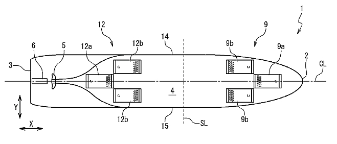
the ship is viewed from a ship bottom side. A bow 2 of a
hull 1 is drawn on a right side, and a stern 3 is drawn on a
left side. A propeller 5 and a helm 6 are arranged below a
water line on the side of the stern 3. An air ejecting
device 7 is arranged on a side closer to the bow 2 in a ship
bottom 4. An air recovering device 8 is arranged on a side
closer to the stern 3 of the ship bottom 4.
[0025] The air ejecting device 7 contains ejecting side
chambers 9 arranged on the ship bottom 4, a pipe system 10
and a compressor 11. A blower may be used instead of the
compressor 11. The compressor 11 ejects the air inside the
pipe 10 to the direction of the ship bottom 4. One end of
the pipe 10 is connected to an air supply hole (that will be
described later) formed in an outer plate of the ship bottom
4. The ejecting side chamber 9 is attached to the ship
bottom 4 in a position in which the air supply hole is
formed, by welding or tightening bolts. The air inside the
pipe 10 is supplied to the ejecting side chamber 9 by the
compressor 11.
[0026] The air recovering device 8 contains recovery side
chambers 12 and a pipe 13. One end of the pipe 13 is
connected to an air recovery hole (that will be described
later) formed in the outer plate of the ship bottom 4. The
recovery side chamber 12 is attached to the ship bottom 4 in
a position in which the air recovery hole is formed, by
welding or tightening bolts. The air inside the recovery
side chamber 12 is discharged through the pipe 13 to the
outside or again supplied to the pipe 10 on the side of the
air ejecting device 7.
[0027] In examples of FIGS. 1 and 2, a plurality of (three)
ejecting side chambers 9 are attached. An ejecting side
chamber 9a on a front side is attached on a central line CL
of the hull 1, to be line-symmetry with respect to the
central line CL. One of ejecting side chambers 9b on a rear
side is attached to a position shifted on the starboard side
14 in parallel with the ejecting side chamber 9a on the
front side. The other is attached to a position shifted to
the port side 15 in parallel with the ejecting side chamber
9a on the front side. Accordingly, the ejecting side
chambers 9b on the rear side are formed symmetrically with
respect to the central line CL.
[0028] In examples of FIGS. 1 and 2, a plurality of recovery
side chambers 12 are attached in correspondence to the
ejecting side chambers 9. The recovery side chambers 12a and
12b on the rear side and the front side are attached in
correspondence to the ejecting side chambers 9a and 9b on
the front side and the rear side. Each of the recovery side
chambers 12 has a shape similar to the ejecting side chamber
9 and is provided to have an orientation opposite to a
direction of the hull 1. As a result, the ejecting side
chambers 9 and the recovery side chambers 12 are
line-symmetrical with respect to a lateral reference line SL
extending in a lateral direction of the hull 1.
[0029] FIG. 3 schematically shows the operation of the air
lubrication system. The air is supplied from the pipe 10 to
the ejecting side chamber 9. The ejecting side chamber 9
ejects the air as air bubbles 40 to external water. The air
bubbles 40 flow to the stern 3 while covering the ship
bottom 4. Since the ship bottom 4 is covered with the air
bubbles 40, friction between the hull 1 and the water is
reduced. The air bubbles 40 are captured in the recovery
side chamber 12 and recovered from the pipe 13. The air
bubbles 40 are recovered on the side of the bow 2 from the
propeller 5. Thus, it is possible to avoid the drop in a
propulsion efficiency of the propeller 5 due to the air
bubbles 40.
[0030] FIG. 4 shows another configuration example of the
ejecting side chambers 9. In the configuration shown in FIG.
2, the air bubbles 40 that substantially cover the width of
the ship bottom 4 are provided by the three ejecting side
chambers 9. On the contrary, in FIG. 4, in addition to a
group of three ejecting side chambers 12-1 that
substantially covers the width of the ship bottom 4, a group
of three ejecting side chambers 12-2 that has the similar
configuration is further placed in a position away in a
length direction of the hull 1. In this configuration
example, a larger number of the air bubbles 40 can be
supplied to the ship bottom 4. Or, when the air bubbles 40
easily escape from the left and right sides of the ship
bottom 4, so that the air bubbles 40 supplied from the
ejecting side chambers 12-1 come short on the side of the
stern 3, the air bubbles 40 can be supplemented from the
ejecting side chambers 12-2 of a next stage. In such a case,
the air bubbles 40 can be recovered by placing a plurality
of groups of recovering side chambers on the side of the
stern 3 line-symmetrically with a plurality of groups of
ejecting side chambers 12-1, 12-2 and a group of recovery
side chambers with respect to the predetermined reference
line SL.
[0031] The configuration of the ejecting side chamber 9 will
be described below. FIG. 5 is a bottom view of the ejecting
side chamber 9. FIG. 6 is a sectional view when the ejecting
side chamber 9 is viewed from the side thereof. The right
side in each of FIGS. 5 and 6 indicates the side of the bow
2. The ejecting side chamber 9 contains a flat portion 21, a
front end 22, a rear end 23, a side plate 21-1 and a side
plate 21-2. The flat portion 21 is a plate-shaped member
provided on the lower side of the ship bottom 4. The flat
portion 21 is arranged in parallel to the ship bottom 4 or
at a state almost parallel to the ship bottom 4.
[0032] The front end 22 is a plate-shaped member for
connecting the ship bottom 4 and the end of the flat portion
21 on the bow 2 side. The front end 22 has a slope that
approaches the ship bottom 4 toward the side of the bow 2,
in order to decrease the resistance of water flow when the
hull 1 navigates forwardly. The rear end 23 is a
plate-shaped member for connecting the ship bottom 4 and the
end of the flat portion 21 on the side of the stern 3. The
rear end 23 has a slope that approaches the ship bottom 4
toward the side of the stern 3, in order to suppress the
generation of eddy that serves as resistance when the hull 1
navigates forwardly and further smoothly guide the air
bubbles to the ship bottom 4. The side plate 21-1 closes an
opening formed from the ship bottom 4, and the portside
portion of each of the flat portion 21, the front end 22 and
the rear end 23. The side plate 21-2 closes an opening
formed from the ship bottom 4 and the starboard side portion
of each of the flat portion 21, the front end 22 and the
rear end 23. An air bubble chamber 28 is formed by the flat
portion 21, the front end 22, the rear end 23, the side
plates 21-1 and 21-2 and the ship bottom 4 covered with
them. The space of the air bubble chamber 28 communicates
with the water under the ship through air ejecting holes 26
and also communicates with a pipe 10 through an air supply
hole 27. The space of the air bubble chamber 28 other than
the air ejecting holes 26 and the air supply hole 27 is
closed.
[0033] In the design of the ejecting side chamber 9, the air
bubble chamber 28 is divided into an air scattering section
24 as a region on the side of the bow 2, and an air ejecting
section 25 as a region on the side of the stern 3, as shown
by a dotted line on the flat portion 21 of FIG. 5. A
plurality of the air ejecting holes 26 are formed in the air
ejecting section 25. These air ejecting holes 26 are
arranged in the width direction of the hull 1. In an example
of FIG. 5, two lines of the air ejecting holes 26 are
shifted to each other in a zigzag arrangement in the width
direction of the hull 1.
[0034] The air supply hole 27 is formed at that position of
the ship bottom 4 opposite to the air scattering section 24
which is differing from the air ejecting holes 26 (a
position on the side of the bow 2 in FIGS. 5 and 6). One end
of the pipe 10 is connected to the air supply hole 27. By
the air scattering section 24, a predetermined distance is
provided between the air supply hole 27 and the air ejecting
holes 26 in the longitudinal direction of the hull 1. The
existence of this distance enables the air that is supplied
from the air supply hole 27 to the air bubble chamber 28 is
scattered and consequently enables the air bubbles of a
substantially uniform quantity to be ejected into the water
from the plurality of air ejecting holes 26 arranged in the
width direction of the hull 1. In order to attain the effect
of the air scattering section 24, for example, a distance
between a center of the air supply hole 27 and a center of
the air ejecting hole 26 is desired to be set longer than
the width of the air bubble chamber 28.
[0035] The air, which is supplied from the air supply hole
27 to the air bubble chamber 28, is impinged on the upper
surface (inner wall surface) of the flat portion 21 due to a
pressure given by the compressor 11. The supplied air is
changed into the fine air bubbles due to the pressure of
this impingement, and the width of a distribution is easily
widen. While the air bubbles are pushed toward a downstream
side inside the air scattering section 24, its distribution
is expanded in a width direction.
[0036] Since the air scattering section 24 is provided, the
width of the air supply hole 27 can be made smaller than the
width of the air ejecting holes 26 in the width direction of
the hull. In other words, by providing the air scattering
section 24, the air ejecting holes 26 can be formed to be
distributed in the width direction of the hull 1, even when
the number of air supply holes 27 is small (one in an
example of FIG. 5). Thus, the air bubbles 40 can be ejected
to have a substantially uniform distribution in the width
direction. Accordingly, when the ship is modified to install
the air lubrication system later, the work may be reduced
when the air supply hole 27 and the pipe 10 are attached to
the hull 1.
[0037] A diffusion member can be further added to the
ejecting side chamber 9 to diffuse the air bubbles. For
example, a porous plate is provided between the air supply
hole 27 and the air ejecting holes 26 to partition the air
bubble chamber 28 in the longitudinal direction of the hull
1. Consequently, the finer air bubbles can be supplied to
the air ejecting holes 26.
[0038] When a certain quantity of air bubbles are
accumulated inside the air bubble chamber 28, the air
bubbles 40 are ejected into the water under the ship bottom
4 from the air ejecting holes 26. When the ship sails, the
hull 1 moves in the forward direction against the water. The
water flow has a main direction from the front end 22 of the
ejecting side chamber 9 to the rear end 23 on the ship
bottom 4. On the contrary, since the inner space of the
ejecting side chamber 9 is relatively closed, the flows of
the water and air in the air bubble chamber 28 are slow, as
compared with the external water flow. For this reason, when
the air is ejected from the air bubble chamber 28 through
the air ejecting holes 26, the air is sheared into the finer
air bubbles 40 by shearing force of the external water flow
and sent to the downstream side. Since a time period for
which the air bubbles 40 stay on the ship bottom 4 is long,
the high air lubrication effect is attained. In this way,
without being supplied in its original state to the ship
bottom 4, via the rear end 23 and the like, the air from the
air supply hole 27 once stay in the air bubble chamber 28,
and then the air is supplied to the outside so that the
shearing force acts against the air. Thus, the air bubbles
40 suitable for the air lubrication are obtained.
[0039] Through the design of the shape of the air ejecting
hole 26, the air bubbles 40 can be ejected more smoothly
from the air bubble chamber 28 into water flows whose speeds
are different in the longitudinal direction of the hull 1.
In an example of FIG. 5, each of the air ejecting holes 26
has an oval shape long in the main direction of the flow,
namely, in the longitudinal direction of the hull 1. The air
bubbles 40 ejected from the air ejecting holes 26 rise along
the rear end 23 and flow to the side of the stern 3 while
covering the ship bottom 4, and then arrives at the recovery
side chamber 12.
[0040] The structure of the recovery side chamber 12 will be
described below. FIG. 7 is a bottom view of the recovery
side chamber 12. FIG. 8 is a sectional side view of the
recovery side chamber 12. The right side of each of FIGS. 7
and 8 is the side of the bow 2. The recovery side chamber 9
has the structure similar to the ejecting side chamber 9,
and this is attached to the ship bottom 4 in an opposite
orientation in the longitudinal direction of the hull 1. The
recovery side chamber 12 contains a flat portion 31, a front
end 32, a rear end 33 and side plates 31-1 and 31-2. The
flat portion 31 is a plate-shaped member provided under the
lower side of the ship bottom 4 and is provided in parallel
to the ship bottom 4 to have a gap.
[0041] The front end 32 is a plate-shaped member to connect
the ship bottom 4 and the end of the flat portion 31 on the
side of the bow 2. The front end 32 has a slope that
approaches the ship bottom 4 toward the side of the bow 2,
in order to decrease the resistance of the water flow when
the ship sails. The rear end 33 is a plate-shaped member to
connect the ship bottom 4 and the end of the flat portion 31
on the side of the stern 3. The rear end 33 has a slope that
approaches the ship bottom 4 toward the side of the stern 3,
in order to suppress the generation of the eddy that serves
as the resistance when the hull 1 sails. The side plates
31-1 and 31-2 close side openings by the right and left
sides of the recovery side chamber 12, similarly to the side
plates 21-1 and 21-2 of the ejecting side chamber, and thus,
the air bubble chamber 38 is formed. The air bubble chamber
38 has a space which communicates with the water under the
water surface when the ship floats, through air intake holes
36 and also communicates with the pipe 13 through an air
recovery hole 37, and a portion of the air bubble chamber 38
other than them is closed. The recovery side chamber 12
having such a structure can be attained by providing the
ejecting side chamber 9 on the ship bottom 4 in an opposite
orientation in the longitudinal direction of the hull 1.
[0042] In the design of the recovery side chamber 12, the
flat portion 31 is divided into an air intake section 34 as
a region on the side of the bow 2, and a pushing pressure
generating section 35 as a region on the side of the stern
3, as shown by a dotted line on the flat portion 31 of FIG.
7. A plurality of the air intake holes 36 are formed in the
air intake section 34, similarly to the air ejecting holes
26 of the ejecting side chamber 9.
[0043] The air recovery hole 37 is formed on at a position
of the ship bottom 4 opposite to the pushing pressure
generating section 35. One end of the pipe 13 is connected
to the air recovery hole 37. By the pushing pressure
generating section 35, the air bubble chamber 38 can be
provided to have a certain degree of a volume. The air
bubbles acquired from the air intake holes 36 stay in the
air bubble chamber 38. Since the air bubbles once stay in
the pushing pressure generating section 35, the air of some
quantity is accumulated in the air bubble chamber 38. As a
result, the air bubbles can be smoothly recovered from the
air recovery hole 37.
[0044] In order to suppress the resistance of the water, the
thickness of the recovery side chamber 12 is desired to be
thin. When the length of the pushing pressure generating
section 35 is set long, the sufficient volume of the air
bubble chamber 38 can be attained even if the recovery side
chamber 12 is thin. For this reason, for example, similarly
to the ejecting side chamber 9, a distance between the
center of the air intake hole 36 and the center of the air
recovery hole 37 is desired to be set longer than the width
of the air bubble chamber 38.
[0045] By providing a guide plate 39 in the recovery side
chamber 12, it is possible to smoothly acquire the air
bubbles 40. The guide plate 39 is provided inside the
recovery side chamber 12 to overlap with the air intake
holes 36 when viewing from the lower side. The guide plate
39 is provided to approach the ship bottom 4 in a direction
from the side of the bow 2 to the side of the stern 3 in an
inclined state. By the guide plate 39, the air bubbles 40
acquired from the air intake holes 36 are smoothly sent to
the pushing pressure generating section 35.
[0046] FIGS. 9 and 10 are a bottom view and a sectional view
which show the recovery side chamber in a modification
example of the present embodiment. In the modification
example, the recovery side chamber 12 contains a narrowing
section 41 at the end thereof on its downstream side. In the
narrowing unit 41, the width of the recovery side chamber 12
is narrowed to be gradually reduced toward the downstream
side. More preferably, the narrowing section 41 is
structured by a plate material which approaches the ship
bottom 4 toward the downstream side, similarly to the rear
end 33 in FIG. 8. The air recovery hole 37 is provided at an
upper portion above the narrowing section 41 in the vertical
direction. By such a structure, the air bubbles recovered in
the air bubble chamber 38 are easily collected in the
narrowing section 41, and the air bubbles can be recovered
more efficiently from the air recovery hole 37.
[0047] When the existing ship is modified to install the air
lubrication system in the present embodiment, the air supply
hole 27 and the air recovery hole 37 are formed in the ship
bottom 4. The pipe 10, the pipe 13 and the compressor 11 are
provided within the ship. The ejecting side chambers 9 and
the recovery side chambers 12 are provided in the ship
bottom 4. In this way, it is possible to improve the
efficiency of the navigation of the existing ship. Even when
the air lubrication system in the present embodiment is
installed for a ship to be newly manufactured, the air
lubrication system can be installed under few design
changes, in accordance with the similar procedure.
[0048] The structure of the air lubrication system in the
present embodiment is effective in case of using only the
air recovering device 8. For example, similarly to the
newly-manufactured ship that contains the air lubrication
system, an inner installation type ship is employed in which
the chamber for ejecting the air bubbles is formed inside
the hull 1 and the recovery side chamber 12 is attached from
the outside. Even in this case, the same effect as the
present embodiment can be attained in the air recovering
device 8.
SHIP WITH REDUCED FRICTIONAL RESISTANCE
PROBLEM TO BE SOLVED: To provide an air lubrication system for ships that prevents deterioration of a coating film, and a method of manufacturing a ship with reduced frictional resistance. ; SOLUTION: The air lubrication system 1 for ships includes an air supply device 11, air blowing parts 100A and 100B, and an air cooler 12. The air blowing parts 100A and 100B blow the air supplied from the air supply device 11 into the water. The air supply device 11 pressurizes the air to blow the air against water pressure. The temperature of the air at the outlet of the air supply device is high. If the high-temperature air is blown into the water without cooling it, deterioration of the coating film on the surface of the ship body may be accelerated. The air cooler 12 cools the air using seawater. ;
JP5216122
SHIP WITH REDUCED FRICTIONAL RESISTANCE, AND MANUFACTURING METHOD THEREOF
PROBLEM TO BE SOLVED: To provide an air lubrication system for ships that prevents deterioration of a coating film, and a method of manufacturing a ship with reduced frictional resistance. ; SOLUTION: The air lubrication system 1 for ships includes an air supply device 11, air blowing parts 100A and 100B, and an air cooler 12. The air blowing parts 100A and 100B blow the air supplied from the air supply device 11 into the water. The air cooler 12 cools the air with seawater to prevent deterioration of a coating film. A seawater inlet 20 is also provided for receiving seawater. The air blowing parts and the seawater inlet are arranged at the bottom 80a of the bow. The seawater inlet is arranged closer to the bow than the air blowing parts.
AIR LUBRICATION SYSTEM FOR SHIP, SHIP WITH REDUCED FRICTIONAL RESISTANCE, AND MANUFACTURING METHOD THEREOF
PROBLEM TO BE SOLVED: To provide an air lubrication system for ships that reduces the manufacturing period of a ship with reduced frictional resistance, and the ship with reduced frictional resistance and a manufacturing method thereof. ; SOLUTION: The air lubrication stem for ships includes an air supply device and an air blowing part that blows the air supplied from the air supply device into the water from the bottom. The air blowing part includes a chamber 230A having an air blowing hole 232A. The chamber 230A is detachable, thereby enabling easy manufacturing of the air blowing part. The manufacturing period of the ship with reduced frictional resistance can be reduced. The chamber can be detached for maintenance of the air blowing part.


