rexresearch
John Dodd: "The Techno Maestro's Amazing Machine" (Japan, Inc., March 2004)
Kohei Minato: US Patent # 4,751,486
K. Minato: US Patent # 5,594,289
Henry Curtis: KeelyNet BBS Posts
Michael Randall Emails
Padrak: INE Press Release
Photos
The Techno Maestro's Amazing Machine
Kohei Minato and the Japan Magnetic Fan Company A maverick inventor's breakthrough electric motor uses permanent magnets to make power -- and has investors salivating
by John Dodd
When we first got the call from an excited colleague that he'd just seen the most amazing invention -- a magnetic motor that consumed almost no electricity -- we were so skeptical that we declined an invitation to go see it. If the technology was so good, we thought, how come they didn't have any customers yet?We forgot about the invitation and the company until several months later, when our friend called again.
"OK," he said. "They've just sold 40,000 units to a major convenience store chain. Now will you see it?"
In Japan, no one pays for 40,000 convenience store cooling fans without being reasonably sure that they are going to work.
The Maestro ~
The streets of east Shinjuku are littered with the tailings of the many small factories and workshops still located there -- hardly one's image of the headquarters of a world-class technology company. But this is where we are first greeted outside Kohei Minato's workshop by Nobue Minato, the wife of the inventor and co-director of the family firm.
The workshop itself is like a Hollywood set of an inventor's garage. Electrical machines, wires, measuring instruments and batteries are strewn everywhere. Along the diagram-covered walls are drill presses, racks of spare coils, Perspex plating and other paraphernalia. And seated in the back, head bowed in thought, is the 58-year-old techno maestro himself.
Minato is no newcomer to the limelight. In fact, he has been an entertainer for most of his life, making music and producing his daughter's singing career in the US. He posseses an oversized presence, with a booming voice and a long ponytail. In short, you can easily imagine him onstage or in a convertible cruising down the coast of California -- not hunched over a mass of wires and coils in Tokyo's cramped backstreets.
Joining us are a middle-aged banker and his entourage from Osaka and accounting and finance consultant Yukio Funai. The banker is doing a quick review for an investment, while the rest of us just want to see if Minato's magnetic motors really work. A prototype car air conditioner cooler sitting on a bench looks like it would fit into a Toyota Corolla and quickly catches our attention.
Seeing is Believing ~Nobue then takes us through the functions and operations of each of the machines, starting off with a simple explanation of the laws of magnetism and repulsion. She demonstrates the "Minato Wheel" by kicking a magnet-lined rotor into action with a magnetic wand.
Looking carefully at the rotor, we see that it has over 16 magnets embedded on a slant -- apparently to make Minato's machines work, the positioning and angle of the magnets is critical. After she kicks the wheel into life, it keeps spinning, proving at least that the design doesn't suffer from magnetic lockup.
She then moves us to the next device, a weighty machine connected to a tiny battery. Apparently the load on the machine is a 35kg rotor, which could easily be used in a washing machine. After she flicks the switch, the huge rotor spins at over 1,500 rpms effortlessly and silently. Meters show the power in and power out. Suddenly, a power source of 16 watt or so is driving a device that should be drawing at least 200 to 300 watts.
Nobue explains to us that this and all the other devices only use electrical power for the two electromagnetic stators at either side of each rotor, which are used to kick the rotor past its lockup point then on to the next arc of magnets. Apparently the angle and spacing of the magnets is such that once the rotor is moving, repulsion between the stators and the rotor poles keeps the rotor moving smoothly in a counterclockwise direction. Either way, it's impressive.
Next we move to a unit with its motor connected to a generator. What we see is striking. The meters showed an input to the stator electromagnets of approximately 1.8 volts and 150mA input, and from the generator, 9.144 volts and 192mA output. 1.8 x 0.15 x 2 = 540mW input and 9.144 x 0.192 = 1.755W out.
But according to the laws of physics, you can't get more out of a device than you put into it. We mention this to Kohei Minato while looking under the workbench to make sure there aren't any hidden wires.
Minato assures us that he hasn't transcended the laws of physics. The force supplying the unexplained extra power out is generated by the magnetic strength of the permanent magnets embedded in the rotor. "I'm simply harnessing one of the four fundamental forces of nature," he says.
Although we learned in school that magnets were always bipolar and so magnetically induced motion would always end in a locked state of equilibrium, Minato explains that he has fine-tuned the positioning of the magnets and the timing of pulses to the stators to the point where the repulsion between the rotor and the stator (the fixed outer magnetic ring) is transitory. This creates further motion -- rather than a lockup. (See the sidebar on page 41 for a full explanation).
Real Products ~Nobue Minato leads us to the two devices that might convince a potential investor that this is all for real.
First, she shows us the cooling fan prototype that is being manufactured for a convenience store chain's 14,000 outlets (3 fans per outlet). The unit looks almost identical to a Mitsubishi-manufactured fan unit next to it, which is the unit currently in wide use. In a test, the airflow from both units is about the same.
The other unit is the car air conditioning prototype that caught our eye as we came in. It's a prototype for Nippon Denso, Japan's largest manufacturer of car air conditioners. The unit is remarkably compact and has the same contours and size as a conventional unit. Minato's manufacturing skills are clearly improving.
The Banker and his Investment ~Minato has good reason to complain about Japan's social and cultural uniformity. For years, people thought of him as an oddball for playing the piano for a living, and bankers and investors have avoided him because of his habit of claiming that he'd discovered a breakthrough technology all by himself -- without any formal training.
However, the Osaka banker stands up after the lecture and announces that before he goes, he will commit \100 million to the investment pool.
Minato turns to us and smiles. We brought him good luck, and this was his third investor in as many weeks to confirm an interest.
Bringing the Tech to the Table ~
With the audience gone, we ask Minato what he plans to do to commercialize the technology. His game plan is simple and clear, he says. He wants to retain control, and he wants to commercialize the technology in Japan first -- where he feels he can ensure that things get done right. Why doesn't he go directly to the US or China? His experiences in both countries, he suggests, have been less than successful. "The first stage is critical in terms of creating good products and refining the technology. I don't want to be busy with legal challenges and IP theft while doing that."
Still, the export and licensing of the technology are on his agenda, and Minato is talking to a variety of potential partners in other countries.
Whereas another inventor might be tempted to outsource everything to a larger corporation, part of what drives Minato is his vision of social justice and responsibility. The 40,000 motors for the convenience store chain are being produced by a group of small manufacturers in Ohta-ku and Bunkyo-ku, in the inner north of Tokyo -- which is becoming a regional rust belt. Minato is seized with the vision of reinvigorating these small workshops that until the 80s were the bedrock of Japan's manufacturing and economic miracle. Their level of expertise will ensure that the quality of the motors will be as good as those from any major company.
International Prep ~Despite his plan to do things domestically first, Minato is well prepared for the international markets. He is armed with both six years of living and doing business in Los Angeles in the early 90s -- and with patent protection for over 48 countries. His is hardly a provincial perspective.
His US experience came after playing the piano for a living for 15 years. He began tinkering with his invention in the mid-70s. The idea for his magnetic motor design came from a burst of inspiration while playing the piano.
But Minato decided to drop everything in 1990 to help his daughter Hiroko, who at the age of 20 decided that she wanted to be a rhythm and blues star in the US. Minato is a strong believer in family: If Hiroko was going to find fame and fortune in the US, Dad had better be there to help manage her. He suceeded in helping Hiroko to achieve a UK dance chart number one hit in 1995.
In 1996 Minato returned to Japan and his magnetic motor project. The following year he displayed his prototypes to national power companies, government officials and others at a five-day conference in Mexico City. Interest was palpable, and Minato realized that his invention might meet a global need for energy-saving devices.
Subsequent previews and speeches in Korea and Singapore further consolidated his commitment to bringing the invention to fruition, and he was able to bring in several early-stage investors.
During the late 90s, Minato continued to refine his prototypes. He also stayed in constant contact with his lawyer, registering patents in major countries around the world. Through his experiences in the US he realized that legal protection was critical, even if it meant delaying release of the technology by a couple of years.
Ironically, by the time he'd won patents in 47 countries, the Japanese patent office turned him down on the grounds that "[the invention] couldn' t possibly work" and that somehow he was fabricating the claims.
But a few months later they were forced to recant their decision after the US patent office recognized his invention and gave him the first of two patents. As Minato notes: "How typical of Japan's small-minded bureaucrats that they needed the leadership of the US to accept that my invention was genuine."
By 2001, the Minatos had refined their motors and met enough potential investors to enter into a major international relationship, initially with a Saudi company, to be followed thereafter by companies in the US and elsewhere.
However, fate dealt the investors and Minato's business a serious blow when the World Trade Center was attacked in New York. The Saudis retreated, and Minato's plans fell back to square one.
Now Minato is once again ready to move. With the first order in the works and more orders pending successful prototypes, he has decided that investors don't have to be primary partners. He is actively accepting inquiries from corporate investors who can bring strategic advantages and corporate credibility with them. His company, Japan Magnetic Fan, will make a series of investment tie-up announcements in the first and second quarters of 2004.
Implications ~Minato's motors consume just 20 percent or less of the power of conventional motors with the same torque and horse power. They run cool to the touch and produce almost no acoustic or electrical noise. They are significantly safer and cheaper (in terms of power consumed), and they are sounder environmentally.
The implications are enormous. In the US alone, almost 55 percent of the nation's electricity is consumed by electric motors. While most factory operators buy the cheapest motors possible, they are steadily being educated by bodies like NEMA (National Electrical Manufacturers Association) that the costs of running a motor over a typical 20-year lifespan comprise a purchase price of just 3 percent of the total, and electricity costs of 97 percent. It is not unusual for a $2,000 motor to consume $80,000 of electricity (at a price of .06 cents per kilowatt hour).
Since 1992, when efficiency legislation was put into place at the US federal level, motor efficiency has been a high priority -- and motors saving 20 percent or so on electrical bills are considered highly efficient. Minato is about to introduce a motor which saves 80 percent, putting it into an entirely new class: The $80,000 running cost will drop to just $16,000. This is a significant savings when multiplied by the millions of motors used throughout the USA and Japan -- and eventually, throughout the world.
The Devices ~Minato's invention and its ability to use remarkably less power and run without heat or noise make it perfect for home appliances, personal computers, cellphones (a miniature generator is in the works) and other consumer products.
The magnetic motor will be cheaper than a standard motor to make, as the rotor and stator assemblies can be set into plastic housings, due to the fact that the system creates very little heat. Further, with the motor's energy efficiency, it will be well suited for any application where a motor has limited energy to drive it. While development is still focused on replacing existing devices, Minato says that his motor has sufficient torque to power a vehicle.
With the help of magnetic propulsion, it is feasible to attach a generator to the motor and produce more electric power than was put into the device. Minato says that average efficiency on his motors is about 330 percent.
Mention of Over Unity devices in many scientific circles will draw icy skepticism. But if you can accept the idea that Minato's device is able to create motion and torque through its unique, sustainable permanent magnet propulsion system, then it makes sense that he is able to get more out of the unit than he puts in in terms of elctrical power. Indeed, if the device can produce a surplus of power for longer periods, every household in the land will want one.
"I am not in this for the money," Minato says. "I have done well in my musical career, but I want to make a contribution to society -- helping the backstreet manufacturers here in Japan and elsewhere. I want to reverse the trends caused by major multinationals. There is a place for corporations. But as the oil industry has taught us, energy is one area where a breakthrough invention like this cannot be trusted to large companies."
Minato was once close to making a deal with Enron. But today, he is firmly on a mission to support the small and the independent -- and to go worldwide with them and his amazing machine. "Our plan is to rally smaller companies and pool their talent, and to one day produce the technology across a wide range of fields."
Content provided by J@pan Inc. Magazine -- http://www.japaninc.com
US Patent # 4,751,486Magnetic Rotation Apparatus
(June 14. 1998)
Kohei Minato
Abstract --- The magnetic rotation apparatus of the present invention has first and second rotors rotatably supported and juxtaposed. The first and second rotors are connected so as to be rotatable in opposite directions in a cooperating manner. A number of permanent magnets are arranged on a circumferential portion of the first rotor at regular intervals, and just as many permanent magnets are arranged on a circumferential portion of the second rotor at regular intervals. Each permanent magnet has one magnetic polarity located radially outward from the rotors, and has the other magnetic polarity located radially inward toward the rotors. The polarity of each permanent magnet, which is located radially outward from the rotors, is identical. When the first and second rotors are rotated in a cooperating manner, the phase of rotation of the permanent magnets of one rotor is slightly advanced from that of the permanent magnets of the other rotor. One of the permanent magnets of one rotor is replaced with the electromagnet. The radially outward polarity of the electromagnet can be changed by reversing the direction in which a current is supplied to the electromagnet.
Claims ~ [ Claims not included here ]
Description
TECHNICAL FIELD
The present invention relates to a magnetic rotation apparatus in which a pair of rotors are rotated by utilizing a magnetic force.
BACKGROUND ART
An electromotor is well known as a rotation apparatus utilizing a magnetic force. For example, an AC electromotor comprises a rotor having a coil, a stator surrounding the rotor, and a plurality of electromagnets, disposed on the stator, for generating a rotating magnetic field. An electric power must be constantly supplied to the electromagnets in order to generate the rotating magnetic field and keep the rotor rotating, i.e., an external energy, or electric energy, is indispensable for the rotation of the rotor.
Under the circumstances, a magnetic rotation apparatus, which employs permanent magnets in lieu of electromagnets and can rotate a rotor only by a magnetic force of the permanent magnets, is highly desirable.
The present application proposes a magnetic rotation apparatus which comprises a pair of rotors rotatable in opposite directions in a cooperating manner, and a plurality of permanent magnets stationarily arranged at regular intervals on the peripheral portion of each rotor. One end portion of each permanent magnet of both rotors, which has the same polarity, is located radially outward of the rotors. When the two rotors are rotated in a cooperating fashion, a permanent magnet on one rotor and a corresponding permanent magnet on the other, which form a pair, approach and move away from each other periodically. In this case, the phase of rotation of the magnet on one rotor advances a little from that of the corresponding magnet on the other rotor. When the paired permanent magnets approach each other, magnetic repulsion causes one rotor to rotate. The rotation of one rotor is transmitted to the other rotor to rotate the same. In this manner, other pairs of magnets on both rotors sequentially approach each other, and magnetic repulsion occurs incessantly. As a result, the rotors continue to rotate.
In the above apparatus, in order to stop the rotation of the rotors, a brake device is required. If an ordinary brake device is mounted on the magnetic rotation apparatus, the entire structure of the apparatus becomes complex, and a driving source for the brake device must be provided separately.
The present invention has been developed in consideration of the above circumstances, and its object is to provide a magnetic rotation apparatus including a brake device for suitably stopping the rotation of rotors.
DISCLOSURE OF THE INVENTION
The magnetic rotation apparatus of the present invention is provided with magnetic force conversion means which is substituted for at least one pair of permanent magnets of the paired rotors. In a normal state, the magnetic force conversion means causes a magnetic repulsion, as in the other pairs of permanent magnets. When it is intended for the rotors to stop, the magnetic force conversion means causes a magnetic attraction force. Since a magnetic attraction force can be produced between the rotors at any time, the magnetic attraction force serves to stop the rotors. The brake device constituted by the magnetic force conversion means differs from an ordinary brake device which forcibly stops a pair or rotors by using a frictional force. In the brake device of this invention, by converting a magnetic repulsion force to a magnetic attraction force, the rotors can be braked in the state that the movement of the rotors is reduced. Thus, the rotors can be stopped effectively.
BRIEF DESCRIPTION OF THE DRAWINGS
FIG. 1 is a schematic perspective view showing a magnetic rotation apparatus according to an embodiment of the invention;
FIG. 2 is a schematic plan view showing the relationship between the first and second rotors;
FIG. 3 is a perspective view of a permanent magnet;
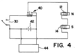
FIG. 4 shows an electromagnet, a permanent magnet cooperating with the electromagnet, and a driving circuit the electromagnet; and
FIG. 5 is a view for explaining how a pair of rotors rotate.
BEST MODE OF CARRYING OUT THE INVENTION
FIG. 1 shows a magnetic rotation apparatus embodying the present invention. The magnetic rotation apparatus has frame 1. Frame 1 is provided with a pair of rotation shafts 2 which extend vertically and in parallel to each other. Shafts 2 are located at a predetermined distance from each other. Upper and lower ends of each shaft 2 are rotationally supported on frame 1 via bearing 3.
First rotor 4a is mounted on one of rotation shafts 2, second rotor 4b is mounted on the other rotation shaft 2. First and second rotors 4a and 4b are arranged on the same level. Rotors 4a and 4b have similar structures. For example, each rotor 4a (4b) comprises two ring-shaped plates 5 which are spaced apart from each other in the axial direction of the rotation shaft 2.
Gears 6a and 6b made of synthetic resin are, as cooperating means, attached to lower surfaces of first and second rotors 4a and 4b. The diameters of gears 6a and 6b are identical but larger than those of rotors 4a and 4b. Gears 6a and 6b mesh with each other. First and second rotors 4a and 4b are thus rotatable in opposite directions in a cooperating manner. In FIG. 1, reference numeral 7 indicates support arms for supporting first and second rotors 4a and 4b.
For example, 16 magnets are arranged at regular intervals on a peripheral portion of first rotor 4a. These magnets are secured between two ring-shaped plates 5. In this embodiment, among the 16 magnets, one is electromagnet 9a (see FIG. 2), and the others are permanent magnets 8a. FIG. 2 shows only some of permanent magnets 8a.
As shown in FIG. 3, permanent magnet 8a comprises case 10, and a plurality of rod-like ferromagnetic members 11 housed in case 10. Ferromagnetic member 11 is, for example, a ferrite magnet. Ferromagnetic members 11 of each permanent magnet 8a are arranged such that ferromagnetic members 11 have the same polarity at one end. In first rotor 4a, for example, an N-polarity end portion of each permanent magnet 8a faces radially outward, and an S-polarity end portion of magnet 8a faces radially inward. As shown in FIG. 2, when each permanent magnet 8a is located between two shafts 2, angle C formed by longitudinal axis A of magnet 8a and imaginary line B connecting two shafts 2 is, for example, set to 30.degree. C. On the other hand, electromagnet 9a is, as shown in FIG. 4, constituted by U-shaped iron core 12, and coil 13 wound around core 12. Electromagnet 9a is arranged such that both N- and S-polarity end portions face radially outward of first rotor 4a, and the above-mentioned angle C is formed, similarly to the case of permanent magnet 8a.
The same number of permanent magnets (8b,9b) as the total number of all permanent magnets and electromagnet (8a,9a) of first rotor 4a are secured on a peripheral portion of second rotor 4b at regular intervals. In FIG. 2, when first and second rotors 4a and 4b are rotated in opposite directions, each permanent magnet of second rotor 4b periodically moves toward and away from the corresponding one of the magnets (8a,9a) of first rotor 4a.
The permanent magnets (8b,9b) of second rotor 4b will now be described in greater detail. Permanent magnets 8b of second rotor 4b, which periodically move toward and away from permanent magnets 8a of first rotor 4a in accordance with the rotation of rotors 4a and 4b, have a structure similar to that of permanent magnets 8a of first rotor 4a. The polarity of that end portion of each permanent magnet 8b which is located radially outward from second rotor 4b, is identical with that of the end portion of each permanent magnet 8a of first rotor 4a. That is, the radially outward portion of each permanent magnet 8b has an N-polarity.
Permanent magnet 9b of second rotor 4b, which periodically moves toward and away from electromagnet 9a of first rotor 4a, has a structure shown in FIG. 4. Permanent magnet 9b has a structure similar to that of permanent magnets 8a. Both polarities of electromagnet 9a face radially outward from first rotor 4a. Permanent magnet 9b has two different polarities which face radially outward from second rotor 4b and correspond to both polarities of electromagnet 9a.
As shown in FIG. 2, when each permanent magnet 8b,9b is located between two rotation shafts 2, angle E formed by longitudinal axis D of the magnet (8b,9b) and imaginary line B connecting two shafts 2 is, for example, set to 56.degree. C. In addition, when rotors 4a and 4b are rotated in opposite directions, as shown by arrows, the magnets (8a,9a) of first rotor 4a move a little ahead of the corresponding permanent magnets (8b,9b) of second rotor 4b, in a region in which both magnets (8a,9a; 8b,9b) approach one another. In other words, the phase of rotation of the magnets (8a,9a) of first rotor 4a advances by a predetermined angle in relation to the permanent magnets (8b,9b) of second rotor 4b.
As shown in FIG. 4, electromagnet 9a of first rotor 4a is electrically connected to drive circuit 14. Drive circuit 14 includes a power source for supplying an electric current to coil 13 of electromagnet 9a. While rotors 4a and 4b rotate, drive circuit turns on electromagnet 9a upon receiving a signal from first sensor 15 only when electromagnet 9a and permanent magnet 9b are in a first region in which they periodically approach each other. First sensor 15 is an optical sensor comprising a light-emitting element and a light-receiving element. As shown in FIG. 1, first sensor 15 is attached to a portion of frame 1 above first rotor 4a. First sensor 15 emits light in a downward direction. The light is reflected by reflection plate 16 projecting radially inward from the inner edge of first rotor 4a. First sensor 15 receives the reflected light, and feeds a signal to drive circuit 14. Thus, drive circuit 14 turns on electromagnet 9a.
The circumferential length of reflection plate 16 is equal to that of the above-mentioned first region. When magnets 9a and 9b enter the first region, first sensor 15 is turned on, and when they leave the first region, first sensor 15 is turned off. When drive circuit 14 receives a signal from first sensor 15, it excites electromagnet 9a such that both polarities of electromagnet 9a correspond to those of permanent magnet 9b of second rotor 4b.
Drive circuit 14 is electrically connected to switching circuit 17. When brake switch 18 is operated, switching circuit 17 reverses the direction in which an electric current is supplied to electromagnet 9a. When the current supplying direction of drive circuit 14 is reversed, drive circuit 14 excites electromagnet 9a only in a time period in which drive circuit 14 receives a signal from second sensor 19. Second sensor 19 has a structure similar to that of first sensor 15, and is attached to frame 1 so as to be located closer to the center of rotor 4a than first sensor 15. Reflection plate 20, which corresponds to the position of second sensor 19, is formed integral to an inner edge portion of reflection plate 16. As shown in FIG. 2, compared to reflection plate 16, reflection plate 20 extends in rotational direction of first rotor 4a, indicated by the arrow.
The operation of the above-described magnetic rotation apparatus will now be explained with reference to FIG. 5.
In FIG. 5, rotation shaft 2 of first rotor 4a is denoted by 01, and rotation shaft 2 of second rotor 4b is denoted by 02. Only the radially outward polarity, that is, N-polarity, of the magnets of rotors 4a and 4b is shown, for the sake of convenience. Although electromagnet 9a and permanent magnet 9b have both polarities located radially outward, only the N-polarity thereof is shown.
When first and second rotors 4a and 4b are put in a position shown in FIG. 5, magnetic pole Nb1 of one permanent magnet of second rotor 4b is located in a line connecting shafts 01 and 02. In this case, polarity Na1 of first rotor 4a, which is paired with polarity Nb1, is a little advanced from polarity Nb1 in the rotational direction of first rotor 4a. For example, as shown in FIG. 5, magnetic pole Na1 is advanced from polarity Nb1 by an angle of X.degree.. Polarities Na1 and Nb1 exert repulsion force F1 upon each other along line L. Supposing that an angle, formed by line M, which is drawn from shaft 01 perpendicularly to line L, and the line connecting shafts 01 and 02 is represented by Y, and that the length of line K is represented by R, torques Ta1 and Tb1 caused by repulsion force F1 to rotate first and second rotors 4a and 4b can be given by:
Ta1=F1.multidot.R.multidot.cos (Y-X)
Tb1=F1.multidot.R.multidot.cos Y
Since cos (Y-X)>cos Y, Ta1>Tb1.
As shown in FIG. 5, since magnetic pole Na1 is advanced from magnetic pole Nb1 by angle X.degree., first rotor 4a receives a greater torque than second rotor 4b. Thus, first rotor 4a forwardly rotates in the direction of the arrow in FIG. 5.
Mention is now made of paired magnets of rotors 4a and 4b in the vicinity of magnetic poles Na1 and Nb1. Magnetic poles Nan and Nan-1 of first rotor 4a are advanced ahead of magnetic pole Nal in the rotational direction. Magnetic poles Nan and Nan-1 receive a torque produced by a repulsion force acting between magnetic poles Nan and Nan-1 and corresponding magnetic poles Nbn and Nbn-1. In FIG. 5, magnetic poles Nan and Nan-1 receive a smaller torque, as they rotate farther from the location of magnetic pole Na1. It is well known that a torque of first rotor 4a, which is caused by a repulsion force acting on magnetic poles Nan and Nan-1, is decreased in inverse proportion to the square of the distance between paired magnetic poles Na and Nb.
Magnetic poles Na2 and Na3, behind magnetic pole Na1, receive a torque which tends to rotate rotor 4a in the reverse direction. This torque is considered to be counterbalanced with the torque acting on magnetic poles Nan and Nan-1.
In FIG. 5, attention should be paid to the region of magnetic poles Na1 and Na2. As first rotor 4a forwardly rotates, the direction in which a torque applies to magnetic pole Na2, is changed from the reverse direction to the forward direction, before magnetic pole Na2 reaches the position of magnetic pole Na1. The torque for forwardly rotating rotor 4a is larger than that for reversely rotating rotor 4a. Therefore, first rotor 4a is easily rotated in the direction shown in FIG. 2.
Second rotor 4b is considered to receive a torque in a direction reverse to the direction shown in FIG. 2, as seen from the description of first rotor 4a. It is obvious that second rotor 4b receives a maximum torque at the position of magnetic pole Nb1. As seen from the above formula, torque Tb1 applied to second rotor 4b in a direction reverse to that denoted by the arrow is smaller than torque Ta1 applied to first rotor 4a in the forward direction. The rotation of first rotor 4a is transmitted to second rotor 4b through gears 6a and 6b. By determining the relationship between the strengths of torques Ta1 and Tb1, second rotor 4b is thus rotated in a direction reverse to the rotational direction of first rotor 4a, against the torque applied to second rotor in the direction. As a result, first and second rotors 4a and 4b are kept rotating, since a torque for rotating rotors 4a and 4b in a cooperating manner is produced each time magnetic poles Na of first rotor 4a pass across the line connecting shafts 01 and 02.
In a diagram shown in the right part of FIG. 5, a solid line indicates a torque applied to first rotor 4a, and a broken line indicates a torque applied to second rotor 4b. The ordinate indicates a distance between each magnetic pole and the line connecting shafts 01 and 02 of rotors 4a and 4b. The first region in which electromagnet 9a of first rotor 4a is turned on is set in a range of Z during which a torque is applied to first rotor 4a in the forward direction.
In order to stop the cooperative rotation of rotors 4a and 4b, brake switch is turned on to operate switching circuit 17. Thus, the direction in which drive circuit 14 supplies a current to electromagnet 9a is reversed. The polarities of electromagnet 9a are reversed. The torque applied to electromagnet 9a in the forward direction is stopped. When electromagnet 9a approaches permanent magnet 9b, a magnetic attract:on force is produced. As a result, the rotation of rotors 4a and 4b is effectively slowed down and stopped. Since the second region, in which electromagnet 9a is excited, is larger than the first region, a large braking force can be obtained from a magnetic attraction force.
In the above embodiment, since electromagnet 9a is excited only in a specific region, a large electric power is not required. In addition, since electromagnet 9a rotates and brakes rotors 4a and 4b, a braking mechanism for a magnetic rotation apparatus can be obtained without having to make the entire structure of the apparatus complex.
The present invention is not restricted to the above embodiment. With the exception of the paired electromagnet and permanent magnet, all permanent magnets of the rotors are arranged such that their end portions of the same polarity face radially outward from the rotors. However, it is possible that the polarities of the radially outward end portions of the permanent magnets are alternately changed. Namely, it should suffice if the polarities of the radially outward end portions of the first rotor are identical to those of the corresponding radially outward end portions of the second rotor. The magnets may have different magnetic forces. Furthermore, an electric power for exciting the electromagnet can be derived from the rotation of the rotors or from the revolving magnetic field of the permanent magnet.
Angles C and E are not restricted to 30.degree. and 56.degree.. They may be freely determined in consideration of the strength of the magnetic force of the permanent magnet, a minimum distance between adjacent magnets, angle x, and the like. The number of magnets of the rotor is also freely chosen.
Industrial Applicability ~
As described above, the magnetic rotation apparatus of the present invention can be used as a driving source in place of an electric motor, and as an electric generator.
US Patent # 5,594,289 (Cl. 310/152) Magnetic Rotating Apparatus
(January 14, 1997)
Kohei Minato
Abstract --- On a rotor which is fixed to a rotatable rotating shaft, a plurality of permanent magnets are disposed along the direction of rotation such that the same magnetic pole type thereof face outward. In the same way, balancers are disposed on the rotor for balancing the rotation of this rotor. Each of the permanent magnets is obliquely arranged with respect to the radial direction line of the rotor. At the outer periphery of the rotor, an electromagnet is disposed facing this rotor, with this electromagnet intermittently energized based on the rotation of the rotor. According to the magnetic rotating apparatus of the present invention, rotational energy can be efficiently obtained from permanent magnets. This is made possible by minimizing as much as possible current supplied to the electromagnets, so that only a required amount of electrical energy is supplied to the electromagnets.
Claims --- [ Claims not included here ]
Description
BACKGROUND OF THE INVENTION
1. Field of the Invention
The present invention relates to a magnetic rotating apparatus, and more particularly, to a magnetic rotating apparatus which utilizes repulsive forces produced between a permanent magnet and an electromagnet.
2. Description of the Prior Art
In a conventional electric motor, an armature as a rotor consists of turns of wires, and electric field as a stator consists of a permanent magnet. In such the conventional electric motor, however, current must be usually supplied to windings of the armature which is rotated. When the current is supplied, heat is generated, which gives rise to the problem that not much driving force is efficiently generated. This, in turn, gives wise to the problem that the magnetic forces cannot be efficiently obtained from the permanent magnet.
In addition, in the conventional electric motor, since the armature is so constructed as consisting of the windings, the moment of inertia cannot be made very high, so that enough torque cannot be obtained.
To overcome the above-described problems of such the conventional electric motor, the inventor proposed, in Japanese Patent Publication No. 61868/1993 (U.S. Pat. No. 4,751,486) a magnetic rotating apparatus in which a plurality of the permanent magnets are disposed along the two rotors, respectively, at a predetermined angle, and in which an electromagnet is disposed at one of the rotors.
In a generally constructed conventional electric motor, there is a limit as to how much the efficiency of energy conversion can be increased. In addition, the torque of the electric motor cannot be made high enough. For the above reasons, hitherto, various improvements have been made on existing electric motors, without any success in producing an electric motor so constructed has providing satisfactory characteristics.
In the magnetic rotating apparatus disclosed in Japanese Patent Publication No. 6868/1993 (U.S. Pat. No. 4,751,486) a pair of rotors is rotated. Therefore, it is necessary for each of the rotors to have high precision, and in addition, measures must be taken for easier rotation control.
SUMMARY OF THE INVENTION
In view of the above-described problems, the object of the present invention is to provide a magnetic rotating apparatus in which rotational energy can be efficiently obtained from the permanent magnet with a minimum amount of electrical energy, and in which rotation control can be carried out relatively easily.
According to one aspect of the present invention, there is provided a magnetic rotating apparatus comprising a rotating shaft; a rotor which is fixed to the rotating shaft and which has disposed thereon permanent magnet means and means for balancing rotation, the permanent magnet means being disposed such that a plurality of magnetic poles of one (or first) polarity type is arranged along an outer peripheral surface in the direction of rotation, and a plurality of magnetic poles of the other (or second) polarity type arranged along an inner peripheral surface, with each pair of corresponding magnetic poles of one and the other polarities obliquely arranged with respect to a radial line; electromagnet means, which is disposed facing this rotor, for developing a magnetic field which faces the magnetic field of the permanent magnet means of the rotor and detecting means for detecting rotating position of the rotor to allow the electromagnet means to be energized.
According to another aspect of the present invention, there is provided a magnetic rotating apparatus comprising a rotating shaft a rotor which is fixed to the rotating shaft and which has disposed thereon a plurality of permanent magnets and balancers for balancing rotation, the permanent magnets being disposed such that one magnetic polarity type is arranged along an outer peripheral surface in the direction of rotation and the other magnetic polarity type arranged along an inner peripheral surface, with each pair of corresponding magnetic poles of one and the other polarities obliquely arranged with respect to a radial line; an electromagnet, which is disposed facing this rotor, for developing a magnetic field which produces the other magnetic polarity type on the facing surface; and energizing means for intermittently energizing the electromagnet means from where the leading permanent magnet, based on the rotation of the rotor, passes the facing surface of the electromagnet in the direction of rotation.
According to still another aspect of the present invention, there is provided magnetic rotating apparatus comprising a rotating shaft; a first rotor which is fixed to the rotating shaft and which has disposed thereon permanent magnet means and means for balancing rotation, the permanent magnet means being disposed such that a plurality of magnetic poles of the second polarity type is arranged along an outer peripheral surface in the direction of rotation, and a plurality of magnetic poles of the first pole type arranged along an inner peripheral surface, with each pair of corresponding magnetic poles of one and the other polarities obliquely arranged with respect to a radial line; a second rotor which rotates along with the first rotor and is fixed to the rotating shaft, having disposed thereon a plurality of permanent magnets and balancers for balancing rotation, the permanent magnets being disposed such that one magnetic polarity type is arranged along an outer peripheral surface in the direction of rotation and the other magnetic polarity type arranged along an inner peripheral surface, with each pair of corresponding magnetic poles of one and the other polarities obliquely arranged with respect to a radial line a first and a second electromagnet means, which are magnetically connected and disposed facing the first and second rotors, respectively, for developing a magnetic field which faces the magnetic field of the permanent magnet means of the first and second rotors; and detecting means for detecting rotating position of the rotors to allow the electromagnet means to be energized.
The nature, principle and utility of the invention will become more apparent from the following detailed description when read in conjunction with the accompanying drawings.
BRIEF DESCRIPTION OF THE DRAWINGS
In the accompanying drawings:
FIG. 1 is a perspective view schematically illustrating a magnetic rating apparatus according to one embodiment of the present invention
FIG. 2 is a side view of the magnetic rotating apparatus illustrated in FIG. 1;
FIG. 3 is a plan view of a rotor of the magnetic rotating apparatus illustrated in FIGS. 1 and 2;
FIG. 4 is a circuit diagram illustrating a circuit in the magnetic rotating apparatus shown in FIG. 1;
FIG. 5 is a plan view showing a magnetic field distribution formed between the rotor and the electromagnet of the magnetic rotating apparatus shown in FIGS. 1 and 2, and
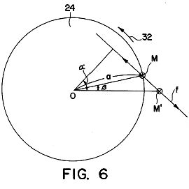
FIG. 6 is an explanatory view illustrating a torque which causes rotation of the rotor of the magnetic rotating apparatus shown in FIGS. 1 and 2.
DESCRIPTION OF THE PREFERRED EMBODIMENTS
The magnetic field developed by an electromagnet means and that of a permanent magnet means of a rotor repel each other. In addition, the magnetic field of the permanent magnet means is flattened by the magnetic fields of other nearby permanent magnets and electromagnet means. Therefore, a torque is produced therebetween to efficiently rotate the rotor. Since the rotor has a high inertial force, when the rotor starts rotating, its speed increases by the inertial force and the turning force.
A magnetic rotating apparatus related to one embodiment of the present invention will be described with reference to the following drawings.
FIGS. 1 and 2 are schematic diagrams of a magnetic rotating apparatus related to one embodiment of the present invention. In the specification, the term "magnetic rotating apparatus" will include an electric motor, and from its general meaning of obtaining turning force from the magnetic forces of permanent magnets, it will refer to a rotating apparatus utilizing the magnetic forces. As shown in FIG. 1, in the magnetic rotating apparatus related to one embodiment of the present invention, a rotating shaft 4 is rotatably fixed to a frame 2 with bearings 5. To the rotating shaft 4, there are fixed a first magnet rotor 6 and a second magnet rotor 8, both of which produce turning forces and a rotated body 10, which has mounted therealong a plurality of rod-shaped magnets 9 for obtaining the turning forces as energy. They are fixed in such a manner as to be rotatable with the rotating shaft 4. At the first and second magnet rotors 6 and 8, there are provided, as will be described later in detail with reference to FIGS. 1 and 2, a first electromagnet 12 and a second electromagnet 14 respectively are energized in synchronism with rotations of the first and second magnet rotors 6 and 8, both of which face each other and are each disposed in a magnetic gap. The first and second electromagnets 12 and 14 are respectively mounted to a yoke 16, which forms a magnetic path.
As shown in FIG. 3, the first and second magnet rotors 6 and 8 each have disposed on its disk-shaped surface a plurality of tabular magnets 22A through 22H for developing a magnetic field for generating the turning forces and balancers 20A through 20H, made of non-magnetic substances, for balancing the magnet rotors 6 and 8. In the embodiments, the first and second magnet rotors 6 and 8 each have disposed along the disk-shaped surface 24 at equal intervals the eight tabular magnets 22A through 22H along half of the outer peripheral area and +the eight balancers 20A through 20H along the other half of the outer peripheral area.
As shown in FIG. 3, each of the tabular magnets 22A through 22H are disposed so that its longitudinal axis 1 makes an angle D with respect to a radial axis line 11 of the disk-shaped surface 24. In the embodiment, an angle of 30 degrees and 56 degrees have been confirmed for the angle D. An appropriate angle, however, can be set depending on the radius of the disk-shaped surface 24 and the number of tabular magnets 22A through 22H to be disposed on the disk-shaped surface 24. As illustrated in FIG. 2, from the viewpoint of effective use of the magnetic field, it is preferable that the tabular magnets 22A through 22H on the first magnet rotor 6 are positioned so that their N-poles point outward, while the tabular magnets 22A through 22H on the second magnet rotor 8 are positioned so that their S-poles point outward.
Exterior to the first and second magnet rotors 6 and 8, the first and second electromagnets 12 and 14 are disposed facing the first and second magnet rotors 6 and 8 respectively in the magnetic gap. When the first and second electromagnets 12 and 14 are energized, they develop a magnetic field identical in polarity to the their respective tabular magnets 22A through 22H so that they repel one anther. In other words, as shown in FIG. 2, since the tabular magnets 22A through 22H on the first magnet rotor 6 have their N-poles facing outwards, the first electromagnet 12 is energized so that the side facing the first magnet rotor 6 develops an N-polarity. In a similar way, since the tabular magnets 22A through 22H on the second magnet rotor 8 have their S-poles facing outwards, the second electromagnet 14 is energized so that the side facing the tabular magnets 22A through 22H develops a S-polarity. The first and second electromagnets 12 and 14, which are magnetically connected by the yoke 16, are magnetized so that the sides facing their respective magnet rotors 6 and 8 are opposite in polarity with respect to each other. This means that the magnetic fields of the electromagnets 12 and 14 can be used efficiently.
A detector 30, such as microswitch, is provided to either one of the first magnet rotor 6 or second magnet rotor 8 to detect the rotating position of the magnet rotors 6 and 8. That is, as shown in FIG. 3, in a rotational direction 32 of the tabular magnets 22A through 22H, the first and the second magnet rotors 6 and 8 are respectively energized when the leading tabular 22A has passed. In other words, in the rotational direction 32, the electromagnet 12 or 14 is energized when starting point So, located between the leading tabular magnet 22A and the following tabular magnet 22B coincides with the center point Ro of either the electromagnet 12 or 14. In addition, as illustrated in FIG. 3, in the rotational direction 32 of the tabular magnets 22A through 22H, the first and the second magnet rotors 6 and 8 are de-energized when the last tabular magnet 22A has passed. In the embodiment, an end point Eo is set symmetrical to the starting point So on the rotating disk-shaped surface 24. When the end point Eo coincides with the center point Ro of either the electromagnet 12 or 14, the electromagnet 12 or 14 is de-energized, respectively. As will be described later, with the center point Ro of the electromagnet 12 or 14 arbitrarily set between the starting point So and the end point Eo, the magnet rotors 6 and 8 start to rotate when the electromagnets 12 and 14 and their tabular magnets 22A through 22H face one another. When a microswitch is used as the detector 30 for detecting the rotating position, the contact point of the microswitch is allowed to slide along the surface of the rotating disk-shaped surface 24. A step is provided for the starting point So and the end point Eo so that the contact of the microswitch closes between the starting point So and the end point Eo. The area along the periphery therebetween protrudes beyond the other peripheral areas of the rotating disk-shaped surface 24. It is apparent that a photo sensor or the like may be used instead of the microswitch as the detector 30 for detecting the rotating position.
As shown in FIG. 4, the windings of the electromagnets 12 and 14 are connected to a DC power source 42 through a movable contact of a relay 40, which is connected in series with the windings. A series circuit containing the relay 40 (solenoid) and the detector 30 or microswitch is connected to the DC power source 42. In addition, from the viewpoint of energy conservation, a charger 44 such as a solar cell is connected to the DC power source 42. It is preferable that the DC power source 42 is constantly chargeable using solar energy or the like.
In the magnetic rotating apparatus illustrated in FIGS. 1 and 2, a magnetic field distribution shown in FIG. 5 is formed between the tabular magnets 22A through 22H, disposed on each of the magnet rotors 6 and 8, and the electromagnets 12 and 14 which face them, respectively. When the electromagnet 12 or 14 is energized, a magnetic field of a tabular magnet of the tabular magnets 22A through 22H, adjacent to the electromagnet 12 or 14, is distorted in the longitudinal direction in correspondence with the rotational direction. This results in the generation of a repulsive force therebetween. As is apparent from the distortion of the magnetic field, the repulsive force has a larger component in the longitudinal or perpendicular direction, and produces a torque, as shown by an arrow 32. Similarly, a magnetic field of a tabular magnet of the tabular magnets 22A through 22H, which next enters the magnetic field of the electromagnet 12 or 14, is distorted. Since it moves toward an opposite pole of the preceding tabular magnet of the tabular magnets 22A through 22H, its magnetic field is distorted to a larger extent, and thereby flattened. This means that the repulsive force produced between the tabular magnets of the tabular magnets 22A through 22H, which have already entered the magnetic field of the electromagnets 12 or 14, is larger than the repulsive force developed between the next-entering tabular magnets of the tabular magnets 22A through 22H and the electromagnets 12 or 14. Accordingly, a turning force, shown by the arrow 32, acts upon the rotating disk-shaped surface 24. The rotating disk-shaped surface 24, having been imparted thereto turning force, continues to rotate due to inertial forces, even when it has been de-energized after the end point Eo has coincided with the center point Ro of the electromagnet 12 or 14. The larger the inertial force, the smoother the rotation.
At the initial stage of the rotation, an angular moment, as that shown in FIG. 6, is imparted to the rotating disk-shaped surface 24. That is, at the start of the rotation, as shown in FIG. 6, when the pole M of a tabular magnet is slightly displaced in the rotational direction from the pole M' of an electromagnet, a repulsive force operates between both of the poles M and M' of the tabular magnet at the rotating side and the electromagnet at the stationary side, respectively. Therefore, from the relationship illustrated in FIG. 6, an angular torque T is generated based on the formula: T=F. a.cos (.alpha.-.beta.), where in a is a constant. The angular torque starts the rotation of the rotating disk-shaped surface 24. After the rotating disk-shaped surface 24 has started rotating, its rotating speed gradually increases due to an inertial moment thereof, which allows a large turning driving force to be produced. After a stable rotation of the rotating disk-shaped surface 24 has been produced, when a necessary electromotive force can be developed in an electromagnetic coil (not illustrated) by externally bringing it near a rotated body 10 to be rotated along with the rotating disk-shaped surface 24. This electric power can be used for other applications. This rotating principle is based on the rotating principle of the magnetic rotating apparatus already disclosed in Japanese Patent Publication No. 61868/1993 (U.S. Pat. No. 4,751,486) by the inventor. That is, even if an electromagnet, provided for one of the rotors of the magnetic rotating apparatus disclosed in the same Patent Application, is fixed, it is rotated in accordance with the rotating principle disclosed therein. For details, refer to the above Japanese Patent Publication No. 61868/1993 (U.S. Pat. No. 4,751,486).
The number of tabular magnets 22A through 22H is not limited to "8" as shown in FIGS. 1 and 3. Any number of magnets may be used. In the above-described embodiment, although the tabular magnets 22A through 22H are disposed along half of the peripheral area of the disk-shaped surface 24, and the balancers 20A through 20H are disposed along the other half of the peripheral area, the tabular magnets may further be disposed along other areas of the disk-shaped surface 24. It is preferable that balancers, in addition to magnets, are provided along a portion of the peripheral area on the disk-shaped surface. The counter weights, which do not need to be formed into separate blocks, may be formed into one sheet of plate which extends on the outer peripheral area of the disk-shaped surface. In addition, in the above-described embodiments, while the construction is such as to allow the electromagnets to be energized for a predetermined period of time for every rotation of the rotating disk-shaped surface, the circuit may be so constructed as to allow, upon increased number of rotations, energization of the electromagnets for every rotation of the rotating disk-shaped surface, starting from its second rotation onwards. Further, in the above-described embodiment, a tabular magnet has been used for the permanent magnet, but other types of permanent magnets may also be used. In effect, any type of magnet may be used as the permanent magnet means as long as a plurality of magnetic poles of one type is disposed along the outer surface of the inner periphery and a plurality of magnetic poles of the other type are disposed along the inner peripheral surface of the disk-shaped surface, so that a pair of corresponding magnetic poles of one and the other polarities is obliquely arranged, with respect to the radial line 11, as shown in FIG. 3.
Although the tabular magnets 22A through 22H are mounted on the magnet rotors 6 and 8 in the above embodiment, they may be electromagnets. In this case, the electromagnets 12 and 14 may be the alternative of electromagnets or permanent magnets.
According to the magnetic rotating apparatus of the present invention, rotational energy can be efficiently obtained from permanent magnets. This is made possible by minimizing as much as possible current supplied to the electromagnets, so that only a required amount of electrical energy is supplied to the electromagnets.
It should be understood that many modifications and adaptations of the invention will become apparent to those skilled in the art and it is intended to encompass such obvious modifications and changes in the scope of the claims appended hereto.
KeelyNet: BBS Posting from Henry Curtis (11-18-1997)Korean Magnetic Perpetual Motion Wheel
I must apologize for not having all the details of this interesting device but will update the file when I get more info from the source. In email communications with John Schnurer, I happened to mention it and he's been on me since then to send him a diagram, yet I felt like it would simply be confusing because its operation is not clear or readily apparent from the information I had.The information that I have comes directly from long time friend Henry Curtis of Colorado. We both attended the 1997 ISNE conference in Denver and Henry was telling about this interesting machine he had seen while on a trip to the Phillipines. He said there was a free energy conference held there and he noticed a spinning bicycle wheel that was attached to a stand that sat on a table.The wheel was running when he first saw it, yet there did not appear to be any driving force such as a motor, belts, gears, etc..Henry said he watched it for quite awhile and it never stopped running. On expressing curiosity about the wheel, he was invited to stop it and start it up without any outside assistance.Henry reports the wheel was brought to a complete stop, then he gave it a spin with his hand and it began moving on its own. I am uncertain if it followed the tendency of other such devices to establish its own speed. Some devices like this can be spun up to high speed from an outside source, then will slow to a speed which is determined by the geometry and strength of the repelling or attracting forces that operate it.Henry swears it was the neatest thing he'd ever seen and drew a crude diagram of the arrangement on my notepad. Unfortunately, we were a bit rushed and I did not achieve a complete understanding of how it operated. That is why I did not want to blow smoke about it until more detail had been received, god knows, we don't need any more of that.However, perhaps someone can figure it out from the limited information I do have. The following drawing shows the wheel arrangement, one half was weighted, the other half had slanted magnets. I do not know whether they are all repelling, attracting or a mix of these forces.
As you can imagine, the weight of the magnets must equal the weight of the other half of the wheel to balance out. Apparently the force of the magnetic repulsion or attaction provides the actual imbalance.Henry also said there was a patent on this device that is dated January 14, 1997. The inventor is a Japanese man named Minatu. The spelling of this name is uncertain. I did a search on the IBM server but found nothing even remote. Henry specifically said this was a United States patent. So, here it is. Perhaps Henry can come up with some more detail which can be used to update this file in future. Good luck....
KeelyNet: Update and Corrections from Henry Curtis (Wed, 19 Nov 1997) ~
From: Henry Curtis ~ To: Jerry Decker
Subject: Bicycle wheel correction and update Jerry, Again we see that communication is difficult and memories are fallable. Obviously I am remiss in not having sent this to you months ago as I intended to, but as a sage of old observed "The spirit is willing, but the flesh is slow." During the first weekend of May, 1997, a group in Soeul, Korea headed up by Mr. Chi San Park, held The First International New Energy Conference in Seoul, Korea. I attended this conference and gave a talk on various approcahes to free energy. It was at this conference in Seoul, Korea that I saw the bicycle wheel and had the opportunity to work with it unattended by anyone else.The inventor is Kohei Minato, a Japanese rock musician, who reports that he has spent a million dollars out of his own pocket developing magnetic motors, because the world needs a better source of energy. He has several patents in various countries. His latest patent that I am aware of is United States Patent # 5,594,289. His development efforts have gone in the general direction of the Adams motor which the above patent is similar to. He had a working prototype of this design at the conference and reported that it used 150 watts power input and produced 450 watts output on a sustained basis. About a year ago CNN (in the US) had a 10 minute segment about him and his motors. In this video he is shown demonstrating two of his magnetic motors. I have a copy of this film clip that he gave to me. I will make a copy and send it to you. Unfortunately, the editors were not attuned to technical details and the pictures of the running machines show little useful detail. The Phillipine connection that you mention is completely erroneous. It was in Korea. The drawing on the web site is essentially correct with the following exceptions. The counter weight is a single curved piece of aluminum covering 180 degrees. Each of the several individual magnets on the other half of the wheel are slightly asymmetric, crescent shaped and nested. They are magnetised end to end with the N poles out. The motor is actuated by moving the N pole of a large permanet magnet (the drive magnet) toward the wheel. As this magnet is moved toward the wheel, the wheel starts to spin. As the magnet is moved closer to the wheel it spins faster. The acceleration of the wheel is rapid. So rapid in fact, as to be startling. To put it another way I was very impressed. The motor works. And it works very well. In the film clip a slight pumping action of Minato's hand holding the magnet is apparent. When I braced my hand so that there was no pumping action, the motor still ran. In fact it seemed to run better. Pumping action by the hand held magnet is not the power that drives the motor. When the drive magnet is moved away from the wheel it coasts rather quickly to a stop and comes to rest in a manner typical of any spinning bicycle wheel. Again when the wheel is at rest and a large magnet is moved up to the wheel it starts to spin. At no time is it necessary to touch the wheel to get it to rotate. Simply bring the N pole of a large magnet several inches from the wheel. The particular orientation of the wheel when it is at rest seems to have no effect on how well it starts to turn. Irrespective of how the wheel and the magnets on it are sitting; move the drive magnet near, it starts to spin. Move the magnet closer it spins faster. Move the magnet further away it slows up. The wheel was mounted on a stand made of aluminum angle pieces bolted together similar to the diagram in the above mentioned patent. The axle of the wheel was mounted parellel to the surface of the planet. I have attached a rough diagram of the wheel. Apparently the geometry of the magnets on the wheel is very important and subtle. I have built several small models none of which have shown the free energy effects of Minato's machine. The conference in Seoul was attended by several hundred people, most appeared to be under 40 and evenly divided between men and women. Presenters were from Korea, US, Japan, and China. Simultaneous translation was provided for all talks in the 3 day conference. Jerry, I hope this information is useful. I may be contacted by e-mail at mailto:hcurtis@mindspring.com or by phone at 303.344.1458.
KeelyNet: Email from Gene Mallove at Infinite Energy ~
I spoke to Bob Vermillion of Tri-Cosmos Development (Los Angeles, CA 310-284-3250 or fax 310-284-3260) today, just before he left for the three-day demonstrations of the Minato magnetic motor being held in Mexico City, Mexico on July 8, 9, 10th.Three (3) Minato Motors (MM), covered by US Patents # 5,594,289 (Jan 14, 1997) and # 4,751,486 (June 14, 1988), have been brought over from Japan. One was allegedly tested last evening by Grupo Bufete Industrial (supposedly one of the largest power generation construction companies in Mexico and South America). The company engineers were said (by Vermillion) to have measured an output /input ratio of 4.3 / 1. The printed literature, which I received in a Fedex packet from Vermillion states that the device can put out 500 watts (maximum) with an input of 34 watts.For those of you who wonder why the device is not self-sustaining -- oral info from Vermillion is that Minato *will* in the course of one of the demonstrations *remove the battery power supply* and let the device self-run -- presumably with a load. The press release makes no bones about the physics-busting character of the MM: "As rotations per minute (rpm's) increase, the electromagnetic consumption of the stator decreases. This phenomenon is in direct conflict with accepted laws of physics and is achieved through the repelling magnetic fields. It operates without heat, noise, or pollution of any kind. It can be produced in size from ultra-small to very large." It is said in the press release that applications from cell phones to laptop computers are under development. Vermillion told me of other parties who were planning to attend the demonstrations, which will be conducted both in public displays and with private party measurements. These include: ENRON, Bechtel, Tejas (a division of Shell Oil Corporation), Fluor Daniels, Kellogg Corp. .He told me that Hal Fox of New Energy News and the Fusion Information Center will be there (I confirmed with Hal that he will be there and will give us a full report.) I considered going myself (I was invited), but I trust Hal Fox to provide a full report -- he should be back this weekend. Mr. Kohei Minato will be there -- he has already arrived, I understand. He hand carried one of the motors that was already tested yesterday. The wealthy Japanese individual who owns Tri-Cosmos Dev. Co. is Mr. Charly Fujiki. Attendance is by invitation only, but let me here provide the Grupo Bufete numbers: (723-45-78 and Fax 723-47-18 in Mexico City). The exhibition will be in the Grupo Bufete Industrial building.The invitation says: "Mr. Minato, the inventor, will be present to explain and demonstrate his remarkable breakthrough in technology to government and business leaders in Mexico. He will also discuss the possible use (and) application for various other industries, including a giant generator project, based on the principal mechanism being displayed."Daily demonstrations are from 10:30 am to Noon, 4:30 to 5:30 pm and 6 to 7:30 pm. A block diagram of the motor indicates that it is about 500 kg. An arrow indicates that its 500 watt output goes to a load -- schematically indicated as an array of light bulbs. The unit is within a cube 1.2 meters on edge.The diagram shows a solar panel(!!) providing input to the battery that powers the device - I supposes for completeness, but that is obviously silly in view of the claim. Vermillion assured me that this solar panel was not an essential part of the system. One of the two color brochures in the package shows the Minato motor with its charactersitic coils that have their pole faces toward the perimeters of permanent magnet containing wheels that are stacked on an axle. If you look at the thing quickly, you'd think you were looking at a steam turbine. The 1997 patent #5,594,289 states in its abstract: "On a rotor which is fixed to a rotatable rotating shaft, a plurality of permanent magnets are disposed along the direction of rotation such that the same magnetic pole type therof face outward. In the same way, balancers are disposed on the rotor for balancing rotation of this rotor. Each of the permanent magnets is obliquely arranged with respect to the radial direction line of the rotor. At the outer periphery of the rotor, an electromagnet is disposed facing this rotor, with this electromagnet intermittently energized based on the rotation of the rotor.According to the magnetic rotating apparatus of the present invention, rotational energy can be efficiently obtained from permanent magnets. This is made possible by minimizing as much as possible current supplied to the electromagnets, so that only a required amount of electrical energy is supplied to the electromagnets." It will be interesting, indeed, to learn what comes out of this.Perhaps the famous white rabbit disappearing down a hole, or maybe the birth of a revolution? We shall see.
Best wishes,
Dr. Eugene F. Mallove,
Editor-in-Chief Infinite Energy Magazine Cold Fusion Technology, Inc. -- http://www.infinite-energy.com
P.O. Box 2816 Concord, NH 03302-2816
Ph: 603-228-4516 ~ Fax: 603-224-5975
editor@infinite-energy.comKeelyNet: Response from STAG group on Minato Wheel (12-04-97) ~
To: Jerry ~ From: David Heard
Subject: Re: Howdy! Thanks for your mail regarding Minato's Rotation Aparatus. My apologies for the slight delay in replying. Yes, please feel free to put up a link to our site and the photos. I should explain that our group is not in any way conected with Mr. Minato himself. The group STAG is run by foreign scientists who are living in Japan with the aim of distrubuting information between themselves, improving links between Japan and the UK (and elsewhere) and of course to have the odd beer or two. We hold meetings every couple of months and invite speakers to speak on interesting or topical subjects. Mr. Minato was one of the speakers who gave a presentation at one of our meetings. Hence the pictures. I also heard about the Korean conference, and saw a significant report written about it in the conference proceedings (albeit in Korean!). I think it would be really good if other people did produce similar devices. I will pass your comments on to Mr. Minato. He did have a Web page, (in Japanese) with information on it, but I haven't been able to connect to it recently. Thanks again for your mail. Regards,
David Heard, Vice Chairman, STAGAt 02:46 21/11/97 -0800, you wrote:
Hello from Texas! A friend told me he saw the bicycle wheel version at a Korean conference so I posted all the details at KeelyNet...one of our readers found your site and informed me, so I will put up a link to your photos.... Do you think there will be full details on how to build the simple self-running bicycle version posted so that others can duplicate it....this would really set it off if these things were being shown all over the world.... I got copies of the three patents (two by Minato, one by Gavaletz) and have their locations posted on my page....thanks for providing the pictures....I don't think it go bigtime until at least a simplified version that self-runs has beend duplicated by many others....this will set the fire that will draw attention to the rest.....good luck, I and a lot of others will be watching....and please congratulate Mr. Minato on his achievement....if you would like to check out our site; http://www.keelynet.com/index0.htmhttp://www.keelynet.com/gravity/curtis.htm (the device file)
Jerry W. Decker / jdecker@keelynet.com
http://www.keelynet.com /Dr. David Heard
273-1 Kashiwa
Functional Device Labs. ~ Sharp Corporation
Kashiwa, Chiba 277 Japan
Tel. : 0471-34-6116 ~ Fax. : 0471-34-6119
e-mail : david@kasiwa.sharp.co.jpFrom: Michael Randall -- mailto:mrandall@earthlink.net ~ To: Bill Beaty (www.eskimo.com) ~ December 4, 1997
"Minato is going Big-Time!"
Subject: Minato's PPM Update Vortexians: Here is an update on Kohei Minato's over-unity permanent magnet inventions. Minato is currently having manufactured, over in Japan, a large unit, (4) connected 10 foot long units, that can power 30 homes. It is estimated to be finished by February. CNN is scheduled to report on it when ready. Minato also has a home powering unit. Both size units are based on his USA Patent 5,594,289 that uses a battery to start and stop the unit. The USA sales representative is Bob Vermillion and his e-mail address is: polenetic@aol.com
No web site yet but Bob Vermillion's office is in Century City, California and he said he can answer your technical, marketing, and manufacturing questions. He just came back from visiting Minato's lab in Japan and was impressed seeing the units working versus seeing the photo's. A power demonstration unit to is expected to arrive from Japan in January. There currently is no USA manufacturing being done and licenses are available worldwide. I mentioned to Bob that there is also a large interest for a permanent magnet rotor/stator unit that is self-rotating and self-starting, like Minato's bicycle wheel design. I also mentioned that a table top version of this, for the student or as an "executive toy," would sell quite well. He didn't know this. If any of you do e-mail to Bob for info, mention to him about the need for a table top version of the bicycle wheel and where you got his address!
Regards,
Michael RandallFrom: Michael Randall ~ To: freenrg-l@eskimo.com (Bill Beaty), March 4, 1998 ~
"Minato Demo and Update"
Here is an 3/4/98 update on Kohei Minato's over-unity permanent magnet inventions from his USA sales representative's Bob Vermillion and John Kenworthy. Mr. Minato demonstrated at the Japanese "Energy Expo '98" his large unit, (4) connected 10 foot long units that can power 30 homes, and several smaller table top units. CNN, NHK and other TV networks took video's of his devices, and of the whole Expo, but he did not know when it was re-broadcasted. Minato's staff had their own video on for the four day event and Bob is making copies of a typical single day video coverage. There were not any instruments connected to the large unit to measure energy input to output but his table top unit was connected and it showed 48 Watts input to 550 Watts output. Minato's demonstration attracted a lot of public attention by the large daily crowds and also from a number of interested Japanese corporations. Bob said he received all of your e-mail's and took them back with him to Japan and gave a copy to Mr. Minato and his staff to show the interest here in the USA and the world. He has not replied to all of your e-mail's due to there is nothing to report about just yet and he will answer all of your e-mail's when he has at least a demonstration unit to show. They are still waiting for a table top power demonstration unit for their Los Angeles office but the Japanese engineer's want to perfect it first. Bob is looking forward to receiving a magnetic "bicycle wheel" unit in April and interested parties can then schedule an appointment to see the wheel spinning by itself without any energy input! :-)
Regards,
Michael RandallNew Energy News 6(3): 1 (July 1998): Press Release
Institute for New Energy (INE)"The Magnetic Rotating Apparatus"
[If the following Press Release is reporting factual information that can be verified, then this may be the first commercial over-unity rotating, magnetic new-energy device. The first western hemisphere demonstration will be given in Mexico City in early July, 1998.
Inventor Kohei Minato, the Thomas Edison of the new millennium, has acquired more than 50 patents and intellectual property rights from all over the world for the energy creating "Magnetic Rotating Apparatus." Mr. Minato's generating device utilizes the magnetic force of repulsion to create and emerge clean safe energy.
The "Magnetic Rotating Apparatus" employs a number of stationary neodymium magnets arranged at regular intervals on the peripheral portion of a rotor. The polarity of each magnet, which is located radially outward from the rotor, is identical. The machine is started with an electromagnetic stator. When activated, the magnetic fields repel creating rotation of the rotor. As the rotations per minute (rpm's) increase, the electrical consumption to the electromagnetic stator decreases. This phenomenon is in direct conflict with accepted laws of physics and is achieved through the repelling magnetic fields. It operates without heat, noise or pollution of any kind. It can be produced in size from ultra small to very large.
One of the prototypes available for viewing operates with an input of 34 watts of electricity and outputs a maximum of 500 watts. "Magnetic Rotating Apparatus" applications currently under development include usage from cell phones and laptop computers to automobiles and giant power stations.
For more information contact:
Tri-Cosmos Development Co.
1888 Century Park East ~ 19th Floor
Century City, CA 90067
Phone: 310-284-3250 ~ Fax: 310-284-3260
E-mail: tricodev@aol.com
Minato Magnet Motor Bicycle Wheel Demonstration Model
Static & Turning (w/ Actuator @ Top of Wheel)