Ralph
MOODY, Jr.
Back Pressure Turbocharger
Ralph
Moody, Jr.got 84 mpg from a Ford Capri modified with a
turbocharged back-pressure regulator on 4 cylinder Perkins
diesel engine.
http://www.abovetopsecret.com/forum/thread945991/pg1
Ralph
Moody and the Moodymobile
...So I was at work, and working in a hospital, we began
discussing healthcare and the financial problems that are
resulting from the low reimbursements which are directly
impacting patient care. The conversation then progressed to
other ways the government is screwing people, and ended with
this ...
My coworker has an uncle whom I had not heard of, Ralph Moody.
She said she forgets what he did, but he created an 80+ mpg
car 30 years ago, that garnered offer from foreign interests
in excess of 20 million. She said her uncle was very
patriotic, and turned them down wanting to sell the technology
to an American car company perhaps, but not to a foreign
group. This car, which did not start out as a low MPG project,
utilized a carburetor they created to achieve these
outstanding results. The federal government showed a lot of
interest in the car, so much that they confiscated it. My
coworker said the car still sits in a storage area in North
Carolina and that her family is allowed to use it, but the
property can not be passed down, it no longer belongs to them.
I am not one to believe in these magic carburetors, I would
love to know more about this particular car...
http://www.caranddriver.com/columns/al-gore-wasnt-the-only-guy-flogging-an-80-mpg-car
Al
Gore Wasn't the Only Guy Flogging an 80-mpg Car
by
PATRICK BEDARD
"What happened to this?" asks reader Pete Kontes about a 1979
AP wire story clipped from his local paper, the Post-Register,
in Idaho Falls, Idaho.
The headline screams, "Former racer could have energy crisis
killer."
Readers of a certain age will recognize 1979 as the time
between Energy Crisis One and Energy Crisis Two, a grim era of
fuel shortages and lines at gas pumps following the OPEC
embargo of 1973-74.
The "racer" here was Ralph Moody, most famous as the
mechanical wizard who had teamed up with super salesman John
Holman to form Holman-Moody, which went through NASCAR in the
'60s like Patton had gone through Africa two decades before.
According to the old clipping: "In tests recently at Daytona
Beach Community College, Moody's 1979 Mercury Capri test car
got an astounding 84 miles to a gallon. The skeptical test
supervisor, Bill Gordon, who has supervised Environmental
Protection Agency fuel economy tests before, couldn't believe
it. 'It is the car of the century,' Gordon said
enthusiastically after the test."
The article's description of the engine sounds confused. Moody
is quoted as saying, "We took a four-cylinder Perkins block,
converted it to diesel fuel, turbocharged it, and built a
special clutch, transmission, and rear-end setup."
Other sources simply say it was a Perkins diesel, which sounds
more likely.
Those years of iffy fuel supply had the car market in a panic,
with frugal Japanese sedans selling far above sticker price
and Detroit still caught in the Cutlass Supreme era of chromey
two-door hardtop coupes about the size and weight of today's
SUVs but with no space in the back seat. American Motors had
already responded by dragging its compact Hornet sedan out
behind the barn and whacking off most of the useful parts—all
of the trunk and a major section of the back seat—to create
the worthless Gremlin.
Motorists wanted miles per gallon, and they wanted it
instantly. But elephants can't zig. Detroit factories were
mostly tooled for big iron. The industry seemed unresponsive,
and the media had the persistent notion that some guy
somewhere in a one-car garage, armed with only a screwdriver
and a Crescent wrench, could outengineer General Motors. The
papers were filled with breathless stories like the one of
Moody's Capri.
"We just got flooded" with inventors, Howard Padgham
remembered recently. He's retired now after years heading
Chrysler's powertrain engineering. But neither he nor I
remembered Moody's car.
I spent a week in Moody's shop back in 1974 doing field
surgery on this magazine's full-race Pinto after an inglorious
debut at Talladega. Within hours of leaving, we qualified on
the pole for the Charlotte race and later won it with a big
lead. I'm sure the other competitors thought Moody had
uncorked a few speed secrets for me.
If he had sure-fire recipes, he didn't share them. He seemed a
sensible guy, careful about the details as he understood them.
He left the big talk to others.
The rumor had been floating around about a Moody mileage maker
for a few months before the Capri appeared, something on the
order of 60 to 70 mpg. About these numbers, he said later,
"They were a little conservative—on purpose. If you come right
out saying you've got a car that'll get 80 to 90 miles per
gallon, people will think you're some kind of jerk."
Yes, that sounds like the Ralph Moody I knew. He was no Smokey
Yunick. But we'll come to the Smoke's mileage maker in a bit.
Padgham confirms another detail of the times. Most of the
inventors who came forward with magic miles-per-gallon numbers
"were normal people, not charlatans." They set up their tests
at constant speeds, on level roads, with their engines fully
warmed up. In that driving, even the relatively primitive
engines of the time went far on a gallon.
Moody died last summer, so we can't ask him about the Capri,
but I did find it listed in Government Involvement in
Suppressed Inventions, by Pea Research (iaesr.homestead.com).
The lengthy compendium confirms that carburetors were favorite
breakthroughs for Uncle Sam's squelching, along with a
reassuring number of flying saucers. My thanks to Pea Research
for answering reader Kontes's question more eloquently than I
could have.
Before we leave the topic of government suppression, however,
let's put Moody's achievement in perspective: "They" also got
to a "highly modified 1959 Opel" credited with 376.59 mpg.
I don't doubt Padgham when he says most of the inventors
weren't charlatans, but it wasn't always easy to tell the
difference. Early in 1984 I went down to "The Best Damn Garage
in Town," town being Daytona Beach, Florida, along with Don
Sherman, C/D technical director at that time, for a look at
Smokey Yunick's "phase-one adiabatic hot-vapor" engine. It was
a 2.2-liter Chrysler four promising 0 to 60 in six seconds and
50 mpg.
Sherman and I are both engineers by training and wary of those
who claim to have found an end run around the laws of
thermodynamics. Yunick had been doing his rulebook
double-shuffle against NASCAR's canniest tech inspectors for
decades before we arrived. We didn't expect a PowerPoint
presentation. What we got was the full wizard act, a sinewy
guy in the white coveralls you see "before" in the detergent
commercials. Even at breakfast I don't remember that he
removed his bad-cowboy black hat. It was oil-soaked at the
band and permanently embedded with aluminum chips from his
machine shop.
He was 60 then. I think the man and his act were already
inseparable. If you fell for the act, maybe you wouldn't
notice the fundamental outrageousness of his claims. He had a
high-compression engine with a turbocharger. Very risky with
the crude controls of mixture and timing of those days. The
usual technique then and now is to add an intercooler to the
intake stream. Yunick had an interheater instead. Yes,
retaining heat helps efficiency, at least theoretically, but
you might just as well put a .357 Magnum to the cylinder head.
We went out for a test drive. The car pulled like hell. It
pinged like hell, too, and busted a piston early in the
acceleration runs.
Yunick stuck to his story. We didn't buy it. Later I heard
that he had sold his "hot vapor" patents to some big company,
along with a multi-year consulting contract that would keep
the cash flowing into his pockets. For the honest inventors
and for the charlatans alike, that was always the touchdown.
Was he on to something we simply couldn't comprehend? Let's
just say, two decades and many mpg regulations later, I don't
see any "hot vapor" engines.
http://people.com/archive/ralph-moody-may-travel-the-road-to-riches-in-a-diesel-car-that-gets-84-miles-per-gallon-vol-11-no-20/
Ralph
Moody May Travel the Road to Riches in a Diesel Car That
Gets 84 Miles Per Gallon
By
Sandra Hinson
About a year ago Ralph Moody, a legendary stock car driver and
mechanic, was thinking about retiring. “All I wanted to do,”
he says, “was a little bit of nothing.” Today Moody has
postponed the rocking chair in favor of rocking the auto
industry. He and a pal have designed a car with an engine that
gets up to 84 miles to a gallon of diesel fuel. The
Moodymobile, as it’s called, came out of the Oak Hill, Fla.
auto shop of Mike Shetley, whom Moody knew from their days
together on the Ford racing team. Shetley had summoned his old
boss from his Charlotte, N.C. home to help with a complicated
chassis for a Thunderbird replica. Moody, 60, solved the
problem in a week, and soon the men were talking about
building a sports car with a diesel engine. “The idea wasn’t
high mileage in the beginning,” says Shetley, 36. “We wanted a
nice-driving car for the guy who couldn’t afford luxury.”
What they did was modify, inside and out, a four-cylinder
Perkins diesel engine (like those used in motorboats) and drop
it into a 1979 Capri body, adding a turbocharger for extra
power. (The turbocharger reroutes hot exhaust gases that
normally escape from the tail pipe.) The Moodymobile was soon
stirring interest locally and was test-driven by Congressman
Bill Chappell. He immediately wired President Carter: “I’ve
seen it, I’ve driven it and it works.”
A fortnight ago Moody and Shetley drove the car 850 miles to
Washington, D.C. (on 11.1 gallons of fuel) and testified
before the Senate Energy Committee. The car (which is noisier
than a conventional one) faces a stiff battery of
environmental tests before it can be marketed, but Moody is
confident one of the big automakers will buy the rights to the
patent. Ford, Chrysler and General Motors have all expressed
interest.
Born in Massachusetts, Moody raced midget cars as a teenager
and in 1956 joined Ford, later becoming chief mechanic. That
meant giving up competitive driving. “I could still outrun
them,” he proclaims. “I did all the test work.” Champion
drivers like Mario Andretti, A.J. Foyt, Cale Yarborough and
Bobby Allison have won with Moody-groomed Fords. He also
designed much of the safety equipment now standard in stock
cars.
When Ford stopped racing in 1971, Moody opened a small “speed
shop” in Charlotte (a city he, his wife Mitzi, 53, son Ralph
III and daughter Ann have lived in for 23 years). He began
selling race cars to drivers and, as a sideline, refined a
gasoline engine that gets up to 65 miles per gallon. “We put
it on the shelf,” Moody shrugs. “Nobody needed it then.”
Shetley claims — perhaps extravagantly — that they have turned
down $100 million from Arab interests to buy rights to the
Moodymobile, which has cost them $20,000 to develop.
Meanwhile, the designers are filing away in cardboard boxes
the names of private citizens eager to place orders. Possibly
2,000 of the cars will be available late this year for about
$7,000 apiece. And for the time being, Ralph Moody has put off
retirement. “In the old days on the racing circuit, I worked
day and night,” he smiles. “Now it’s only 20 hours a day.”
Popular
Mechanics ( August 1979 )
"Osculate
my tailpipe, Detroit !"

Ralph Moody Jr.
WO9216725
APPARATUS
REGULATING EXHAUST FLOW TO INCREASE BACK PRESSURE IN AN
INTERNAL COMBUSTION ENGINE
Inventor: MOODY RALPH A JR
The internal combustion engine (10) includes a fuel delivery
system (200) and an exhaust system having an apparatus (44)
for regulating exhaust flow to increase engine back pressure.
In response to regulated exhaust flow and increased engine
back pressure, the fuel delivery system (200) is controlled to
decrease fuel flow resulting in increased fuel efficiency of
the engine and decreased exhaust emissions. A forced air
induction system such as a turbocharger (80) or supercharger
may also be used in conjuction with the engine (10). In
preferred embodiments, the exhaust flow regulating apparatus
(44) is either a fixed cross-sectional area orifice or a
variable cross-sectional area orifice.
Background
of the Invention
Internal combustion engines are widely used to provide power
for vehicles and machinery, and therefore, it is desirable to
design these engines so that fuel consumption and emissions
are reduced.
Air flow through conventional diesel internal combustion
engines is not controlled and exhaust flow is generally
increased by designing these engines with reduced exhaust
restrictions. Air flow through conventional gasoline engines
is controlled by restrictions in the induction side which
create lower than wide open throttle combustion pressures
resulting in combustion efficiency losses under normal
operation. Prior art teaches that internal combustion engine
efficiencies are improved by reducing exhaust system
restrictions.In a Society of Automotive Engineers article
titled "The Influence of the Exhaust Back Pressure of a Piston
Engine on Air Consumption, Performance, and Emissions",
January 8-12, 1973, the authors showed that engine air
consumption responds to variation of the ratio of absolute
exhaust back pressure to absolute inlet manifold pressure with
a strong dependence on engine speed, and that exhaust back
pressure affects performance and lowers some exhaust
emissions. The authors, however, did not investigate how fuel
efficiency is affected when exhaust flow is regulated to
increase engine back pressure while at the same time reducing
fuel flow.
Summary
of the Invention
The internal combustion engine of the invention includes a
fuel delivery system and an exhaust system having an apparatus
for regulating exhaust flow through the engine to increase
engine back pressure. In response to regulated exhaust flow
and increased engine back pressure, the fuel delivery system
is controlled to decrease fuel flow resulting in increased
fuel efficiency. Reduced exhaust emissions also result. A
forced air induction system such as a turbocharger or
supercharger may also be used in conjunction with the engine.
In general, the apparatus for controlling exhaust flow and
increasing engine back pressure is any restriction positioned
within the exhaust system of either a diesel or gasoline
(spark ignition) internal combustion engine. In one embodiment
the apparatus is a venturi system having a large opening
tapering to a smaller opening that allows exhaust to flow from
the large opening through the smaller opening. Alternatively,
the exhaust flows through a venturi system having an opening
formed by a fixed side and a movable side adjustable at
various engine operating parameters by an actuating system to
establish a desired increase in back pressure.
The internal combustion engine of the invention directly
contradicts the prior art in that back pressure is increased
resulting in increased fuel efficiency. The advantages of the
internal combustion engine of the invention are that fuel
efficiency is increased because induction side losses of the
gas engine can be reduced, the dynamic combustion pressures of
both diesel and gas engines are increased, exhaust flow in
both diesel and gas engines is controlled, and when utilized
in conjunction with a forced air induction system such as a
turbocharger or supercharger, the invention eliminates the
need for and efficiency losses of a dump valve or wastegate
valve that is normally required for forced air induction
system overpressure protection.
Brief
Description of the Drawings
Fig. 1 is a perspective view of one embodiment of the
internal combustion engine of the invention;
Fig. 2 is a cross-sectional view of apparatus for
regulating exhaust flow to increase engine back pressure
having a large opening tapering to a smaller opening;
Fig. 3 is a cross-sectional view of apparatus having a
variable orifice for adjustably regulating exhaust flow to
increase engine back pressure;
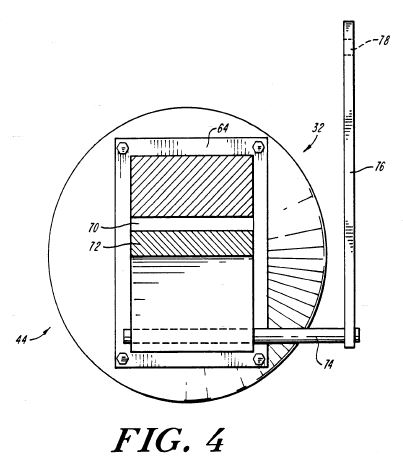
Fig. 4 is a cross-sectional view taken along line 4-4
of the Fig. 3 apparatus;
Fig. 5 is a perspective view of the internal combustion
engine of the invention showing a turbocharger connected to
the exhaust system;
Fig. 6 is a side view of the turbocharger shown in Fig.
5;
Fig. 7 is a front view with parts broken away from the
turbocharger shown in Fig. 5;
Fig. 8 is an alternate perspective view showing a
controllable fuel delivery system;
Fig. 9 is a graph showing intake manifold boost
pressure as a function of RPM;
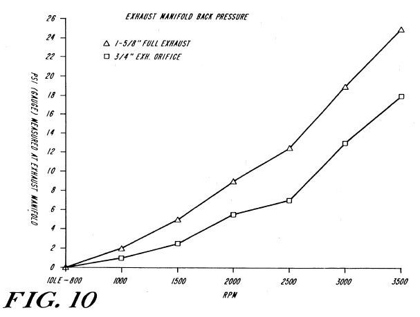
Fig. 10 is a graph showing exhaust manifold back
pressure as a function of RPM; and
Fig. 11 is a graph showing the ratio of boost pressure
to back pressure at maximum acceleration conditions
expressed in gauge pressures as a function of RPM.
Description
of the Preferred Embodiments
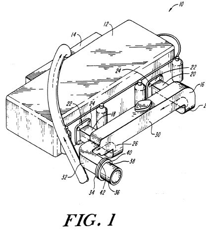
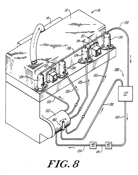
As shown in Fig. 1, an internal combustion engine 10 includes
a cylinder head 12, intake manifold 14, exhaust manifold 16
and a controllable fuel delivery system 200 as shown in Fig.
8. The exhaust manifold 16 includes a pair of hollow spaced
legs 18 and 20 connected to the cylinder head 12 by plates 22
and fasteners 24. Alternatively, plates 22 can be welded to
the cylinder head 12 or be cast integrally with the cylinder
head 12 with the prime consideration being that whatever mode
of connection is used the connection should be substantiaffily
airtight. The free ends of legs 18 and 20 merge at 26 and 28
respectively, preferably in a smooth curvilinear manner, into
a conduit passageway 30 disposed parallel to and spaced from
the cylinder head 12.
The free end of the conduit 30 terminates at an exhaust
section 32, this section preferably being a smooth curved
section, to which a mounting flange 34 is secured. The flange
34 removably supports an exhaust pipe 36 having an inlet 38
terminating in a flange 40 complementally fastened to the
flange 34 by nuts and bolts 42 or similar fasteners.
The controllable fuel delivery system 200 as shown in Fig. 8
comprises a fuel tank 137, fuel line 143, transfer fuel pump
142, fuel line 141, fuel filter 140, fuel line 139, fuel flow
control lever 160, conventional rotary style fuel injection
pump -133, injector lines 135, fuel injectors 134, return fuel
line 138 from the fuel injectors 134, and return fuel line 136
from the fuel injection pump 133. Fuel flows from the fuel
tank 137, to the transfer fuel pump 142, through the filter
140 to the fuel injection pump 133. Rate of fuel flow from the
fuel injection pump 133, via lines 135 to the fuel injectors
134, is controlled by the fuel flow control lever 160.
Residual fuel that is not injected into the engine is then
returned to the fuel tank 137 via the return lines 136 and
138. The purpose for the return lines 136 and 138 is twofold.
First, the return lines 136 and 138 allow for pump and
injector cooling, especially under low load or idling
conditions, and second, they allow for venting of unwanted
gases that may accumulate in the system. The fuel flow spray
pattern of the controllable fuel delivery system 200 may be a
cone shaped fuel flow spray pattern.
It has been found that by regulating the exhaust flow exiting
the engine to increase engine back pressure, air flow entering
the engine can be controlled, and engine efficiency will be
significantly improved when fuel flow is also reduced. Exhaust
emissions will be significantly reduced as compared with
conventional diesel and gas internal combustion engines.
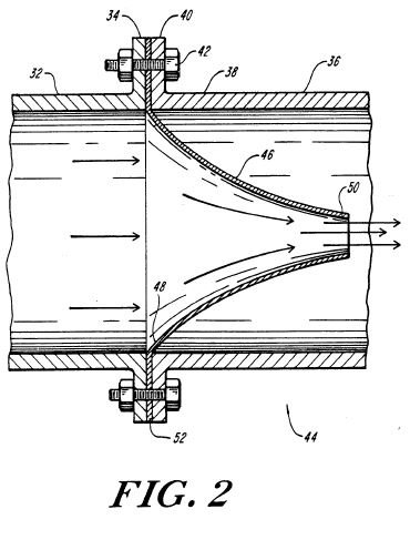
As shown in Fig. 2, this result is obtained by placing
apparatus for controlling exhaust flow to increase engine back
pressure within the exhaust system. A venturi system 44 is
placed between exhaust section 32 of the conduit passageway 30
and the inlet 38 of the exhaust pipe 36. The venturi system
44, in its simplest form, comprises a funnel-like member 46
having a large opening 48 tapering to a smaller opening 50. A
flange 52 disposed about the opening 48 is removably secured
between exhaust section flange 34 and inlet flange 40 by
fasteners 42 for keeping the venturi system 44 in position.
The venturi system 44 may also be formed as an integral part
of exhaust section 32 of conduit 30 or of the inlet 38 of the
exhaust pipe 36.
Exhaust flows from the large opening 48 through the smaller
opening 50, thus regulating exhaust flow to increase engine
back pressure. Operation of the internal combustion engine 10
incorporating the fixed venturi system 44 of Fig. 2 is
identical to the operation of existing internal combustion
engines commonly used in vehicles. The fixed venturi system 44
can also be incorporated into engines, such as industrial
engines, operating under constant loads.
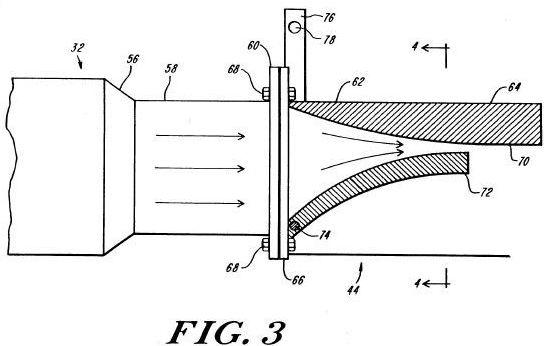
Alternatively, as shown in Figs. 3 and 4, a venturi system 44
is constructed as a variable cross-sectional area venturi
system which can be utilized in engines, such as automobile
engines, operating under a range of dynamic loads. Exhaust
section 32 of conduit 30, shown in Fig. 1, transitions from a
round to rectangular shape at section 56 terminating at
rectangular section 58 having a rectangular flange 60. The
variable venturi system 44 is positioned at the rectangular
inlet 62 of exhaust pipe 64, such rectangular inlet 62 having
a rectangular inlet flange 66 connected to rectangular flange
60 by nuts and bolts 68.
The variable venturi system 44 comprises a fixed converging
side 70, and a moveable side 72, which rotates with a shaft 74
movable by an arm 76 having a hole 78 for connection to an
actuating device (not shown). In addition to increasing engine
back pressure and reducing fuel flow, the variable venturi
system 44 of the invention may be used as the engine's main
control, thus eliminating the induction side throttling device
currently required for operation of non-diesel engines.
Rudimentary operation of the internal combustion engine 10
incorporating the variable venturi system 44 of Figs. 3 and 4
may be accomplished by connecting the throttle pedal (not
shown) to the fuel flow control lever 160 of Fig. 8 and the
arm 76 of Fig. 3 by cam linkages. Actuation of the throttle
pedal will change the position of the fuel flow control lever
160 and cause the arm 76 to vary the position of the movable
side 72 of the venturi system 44.
In another embodiment, operation of the internal combustion
engine 10 incorporating the variable venturi system 44 is
effectuated by a microprocessor (not shown) that receives
information from engine sensors (not shown) that measure
various operating parameters. The microprocessor analyses the
received information and sends optimum position output
information to the fuel flow control lever 160 and arm 76
which, in turn, positions the movable side 72 of the venturi
system 44. Examples of sensors that may be incorporated into
the internal combustion engine 10 of the invention are sensors
that measure oxygen concentration, coolant temperature,
manifold air pressure, vehicle speed, throttle position,
engine RPM, mass air flow, detonation (anti-knock), exhaust
temperature, exhaust manifold pressure and fuel flow.The
throttle pedal, connected to an input transducer (not shown),
in effect, acts as the throttle position sensor. When a forced
induction system such as a turbocharger is used in conjunction
with the engine, as discussed below, additional sensors that
measure boost pressure and turbocharger RPM may also be used
for optimization of the positions of the fuel flow control
lever 160 and the movable venturi system 44.
During engine idle, the variable venturi system 44 and fuel
flow control lever 160 are positioned at a predetermined
minimum setting. The fuel flow, controlled by the fuel flow
lever 160, is continuously and automatically adjusted to
maintain proper fuel mixture based on engine speed, mass air
flow, and oxygen concentration sensor input. The position of
arm 76, as shown in Fig. 3, is continuously and automatically
adjusted for idle speed control. Because engine load may vary
at idle due to accessory demands, the movable side 72 is
constantly repositioned to maintain minimum idle speed.
Upon desired acceleration, the throttle position sensor
delivers an increasing voltage to the microprocessor which, in
turn, increases the opening of the variable venturi system 44.
Based on input from other operating sensors, the fuel flow
control lever 160 is adjusted to regulate fuel flow resulting
in an optimum air to fuel ratio. If maximum engine speed is
achieved inadvertently, the microprocessor can reduce engine
speed by reducing fuel flow and/or air flow by repositioning
the fuel flow control lever 160 and/or the movable side 72 of
the venturi system 44. In addition, if the engine is equipped
with a turbocharger, the manifold air pressure sensor will
supply input to the microprocessor causing the microprocessor,
upon approach of maximum inlet manifold boost pressure, to
begin closing the variable venturi system 44.As this action
occurs, the mass air flow and the fuel flow will be reduced to
maintain air to fuel ratios within an acceptable range.
Oxygen concentration sensors can also be used in conjunction
with mass air flow sensors for maintaining air to fuel ratios.
If the boost pressure increases beyond a desired maximum, the
microprocessor will respond by initially causing the fuel flow
control lever 160 and the movable side 72 to close until an
acceptable air flow and manifold pressure is achieved. The
engine will then return to the desired boost operating mode
and optimum air flow to fuel flow will be retched by the
gradual opening of the venturi 44 which is limited by the
manifold air pressure sensor. When the opening of the venturi
44 is limited, the microprocessor will also limit the opening
of the fuel flow control lever 160 to maintain acceptable fuel
to air ratios while controlling maximum boost pressure.It is
noted that the fixed venturi system 44 of Fig. 2 cannot exceed
a maximum boost pressure because the smaller opening 50 is
designed to control the maximum boost pressure.
At maximum deceleration, fuel flow is completely shut off by
closing the fuel flow control lever 160, and the movable side
72 of the venturi system 44 is returned to a preset minimum
position. When the engine approaches idle speed, the fuel flow
is turned back on and the engine begins operating under idle
conditions. Moderate deceleration is achieved by varying the
position of the movable side 72 based on input from various
operating sensors including the throttle position sensor. Fuel
flow to fuel injectors 134, as shown in Fig. 8, is reduced
proportionally as air flows are reduced by the closing of the
variable venturi system 44.
As previously mentioned, the internal combustion engine 10 of
the invention may be used in conjunction with a forced air
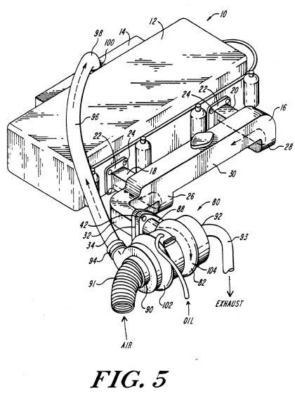
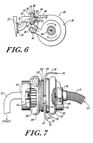
induction system such as a turbocharger. Figs. 5 and 6 show a
removable turbocharger 80 attached to the exhaust section 32
of the internal combustion engine 10 at mounting flange 34
removably supporting the turbocharger 80. A housing 82
included in turbocharger 80 comprises a tangentially disposed
conduit section 84 extending outwardly from the housing 82
with its free end 86 terminating at flange 88 complementally
fastened to flange 34 by nuts and bolts 42 or similar
fasteners.
Further details of the turbocharger 80 are illustrated in
Figs. 5, 6 and 7, and include a totally enclosed generally
cylindrical outer housing 82 having an axially disposed air
inlet 90 having conduit means 91 and an axially disposed
exhaust outlet 92 having conduit means 93, preferably at
opposite ends thereof. An additional radially positioned
opening 94 is provided adjacent to air inlet 90 and
communicates therewith to convey air entering inlet 90 to the
intake manifold 14 by conduit means 96 removably secured at
one end to opening 94 and at the other end 98 to an opening
100 provided in the wall of intake manifold 14.
The housing 82 further includes rotor housing sections 102 and
104, preferably bulbous-like, directly behind the axial
disposed openings 90 and 92 and receiving rotors 106 and 108
each including a plurality of blades 110 and 112,
respectively, radially disposed about a hub in conventional
fashion. The rotors 110 and 112 are mounted on a common shaft
mounted for rotation within housing 82. A recessed section 114
connects the rotor housing sections 102 and 104 and an oil
line 116 communicating with an oil source (not shown). The oil
line 116, positioned at the top of housing 82, discharges oil
into the interior of housing 82 to lubricate the bearings
rotatably supporting the rotor shaft. An oil return line 118
positioned at the bottom of recessed section 114 returns oil
to the source.
The housing 82 is further seen to be formed of section parts
to permit ready access to the interior thereof, and to this
end, the rotor housing section 104 is formed with a flange 120
which is removably secured to flange 122 of recessed section
114 by a standard peripheral clamp (not shown) similar to
standard peripheral clamp 130. The other flange 126 of
recessed section 114 mates with flange 128 of rotor housing
section 102 and is held in place by the standard peripheral
clamp 130 having a nut and bolt means for holding the clamp
130 in place. A gasket 132 or the like, is used (only one
being shown) to make the joints between flanges 120, 122, 126,
128 airtight.
While the weight of the turbocharger 80 is mainly supported by
exhaust manifold 16 and its connection thereto, the conduit
means 91, 93, and 96 associated therewith, also aid in the
suspension of the turbocharger as the free ends thereof are
connected to other supporting structures The free end of
conduit 91 is connected to an atmospheric opening, not shown,
in the vehicle or machine body, and the free end of the
conduit 93 is connected to the exhaust pipe of the vehicle or
machine, and the air conducting conduit 96 is connected to the
intake manifold 14. The conduits 91, 93, and 96 can be made of
any suitable material but it preferred that conduit 91 be made
of rubber or the like of the bellows variety to facilitate
connection of the conduit 91 to component parts.The air
conducting conduit 96 is preferred to be constructed of metal
due to temperature and pressure considerations, connected at
ends 100 and 94 via rubber like hose and metal clamps to
facilitate removal for inspection or repair. The exhaust
conduit 93 is made of metal as it is in contact with high
exhaust temperatures.
Up to this point, the operation of the turbocharger is
standard in that the gases emanating from the exhaust manifold
16 at section 32 are directed against the blades 112 of rotor
108 thereby imparting rotation to the rotor 108, such rotation
causing rotor 106 to rotate with the blades 110 drawing
atmospheric air through conduit 91 into the rotor housing 102
from where it is discharged through conduit 96 into the intake
manifold 14 to increase intake air pressure.
It is known that present day turbochargers are designed in
such a manner that no consideration is given to the control
and use of the air processed by the turbocharger. A dump valve
or wastegate valve is associated with known turbochargers
which opens to vent exhaust when too much exhaust is available
in the turbocharger. This defect, as is apparent, then places
additional strain on the engine in that it causes both the
turbocharger and the engine to process unwanted additional
volumes of exhaust that are then similarly discharged to the
atmosphere via the dump valve or wastegate valve which is
normally located in the exhaust manifold prior to the
turbocharger. These dump valves or wastegate valves are
"pop-off" relief valves actuated by the sensing of excess
pressure at the intake of the engine.
Upon actuation, these valves vent exhaust gases to the
atmosphere, thereby preventing them from flowing through the
turbocharger which would in turn generate additional intake
pressures via the turbocharger function.
It has been found that by regulating the exhaust flow exiting
the engine, air flow entering the engine and boost pressure
produced by the turbocharger can be controlled, and the fuel
efficiency of the engine or engine-turbocharger combination
will be significantly improved. Exhaust emissions are also
substantially reduced as compared to conventional diesel and
gas engines because controlled exhaust flow and increased back
pressure provide for more complete combustion.
The apparatus for regulating exhaust flow to increase engine
back pressure as previously discussed and shown in Fig. 2 is
incorporated into the engine-turbocharger combination to
increase fuel efficiency and reduce exhaust emissions.
The first test engine-turbocharger combination was a Perkins
marine diesel engine with a displacement of 108 cubic inches
fitted into the chassis of a 1979 Mercury Capri. All sharp
edges or contours of combustion area surfaces of the engine,
such as piston top surfaces and surfaces within the cylinder
head combustion chamber and preignition chamber, were slightly
rounded to reduce the potential of concentrated "hotspots"
during operation under leaner fuel ratios. These slight engine
modifications were made to extend engine life and do not
significantly alter or improve the operation of the engine.
The turbocharger attached to the engine was a Rayjay
turbocharger, model #3881882581. Total vehicle weight was
3,300 pounds.The fixed venturi system 44 of Fig. 2 was
incorporated into the first test engine-turbocharger
combination wherein the cross-sectional area of the large
opening 48 was approximately 2.1 square inches, and the
cross-sectional area of the smaller opening 50 was
approximately 0.44 square inches resulting in an approximate
4.7:1 cross-sectional area ratio. The fixed venturi system 44
was secured between mounting flange 34 and flange 88 as shown
in Fig. 6 by nuts and bolts 42.
The first test engine-turbocharger combination having the
fixed venturi system of Fig. 2 was extensively tested.
Certified Environmental Protection Agency mileage and
emissions tests were run with the following results:
Cold start city test: 37.10 miles per gallon
3.40 grams per mile of Carbon Monoxide
0.41 grams per mile of Hydrocarbons
1.00 grams per mile Oxides of Nitrogen
Highway test: 56.23 miles per gallon
2.10 grams per mile of Carbon Monoxide
0.33 grams per mile of Hydrocarbons
0.71 grams per mile Oxides of Nitrogen
At a steady state of 55 miles per hour 63.97 miles per gallon
was achieved.
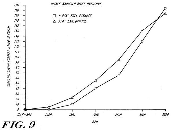
Test results, as shown by the graphs of Figs. 9 and 10,
indicate that the exhaust manifold back pressure and intake
manifold boost pressure can be significantly altered by the
fixed venturi system 44. Increased back pressures on the
engine show additional torque (horsepower) gains in the lower
RPM ranges on both naturally aspirated and turbocharged
engines. Horsepower gains are slightly higher in forced air
induction system applications due to the added effect of
slightly increased boost pressures at lower RPMs.
Test results, however, indicate that engine output horsepower
is not dramatically affected with back pressures exceeding 2
atmospheres, and lower RPM boost pressures can be increased
while flattening the upper RPM boost pressure curve as shown
in Fig. 11.
The ratio of boost pressure to back pressure varies during the
several operational conditions including maximum acceleration,
maximum deceleration, and idle. As shown in Fig. 11, the
maximum boost pressure to back pressure ratio for the first
test engine-turbocharger combination operating at maximum
acceleration was approximately 0.27.
The variable orifice venturi system 44 of Figs. 3 and 4 may
also be incorporated into the engine-turbocharger combination
by forming the free end 86 of conduit section 84 of the
turbocharger shown in Fig. 6 into a rectangular free end 86
having a rectangular flange 88 to complementally join with
rectangular mounting flange 60 by nuts and bolts 68 as shown
in Fig. 3. As shown in Fig. 6, the variable orifice venturi
system 44 includes a fixed side 70 integrally formed with the
turbocharger free end 86, movable side 72, and additional
elements as previously discussed. At higher engine RPM, the
orifice formed by the fixed side 70 and the movable side 72
will be larger than when operating at a lower RPM, except in
the case where boost pressure begins to exceed an upper
control limit predetermined by engine and turbocharger
parameters. When boost pressure approaches the upper control
limit the opening action of the variable orifice venturi
system 44 is retarded, and is reversed as the boost pressure
meets the upper control limit. This closing of the variable
orifice venturi system 44 further increases back pressure on
the engine, thereby reducing exhaust flow, which in turn slows
the turbocharger rotation resulting in reduced boost pressure
and eliminating the need for a dump or wastegate device.