Dr. Paul M. Brown
(Died April 7, 2001) ~ Obituary
rexresearch
Paul BROWN
Resonant Nuclear Battery
( The
Alpha-Beta Voltaic Effect NuCell )
Company Literature (Peripheral Systems, 1980s)
Letter from Paul Brown (excerpt)
Technical Explanation (excerpt)
International Product News
Raum & Zeit
Status Report (1991)
Presentation Paper (American Nuclear Society, 1991)
US Patent # # 4,835,433
USP Application # 2002169351
Dr. Paul M. Brown
(Died April 7, 2001) ~ Obituary
A radioisotope electric power system developed by inventor Paul Brown is a scientific breakthrough in nuclear power. The battery utilizes the energy given off by decaying radioactive material, converting it directly into a continuous AC electrical current. Unlike conventional nuclear generating devices, the power cell does not rely on a nuclear reaction or chemical process and does not produce radioactive waste products.Brown's first prototype power cell produced 100,000 times as much energy per gram of strontium-90 (the energy source) than the most powerful thermal nuclear battery yet in existence. The Nucell battery yielded 7500 watts per gram of strontium-90. Compare this to an advanced device recently developed by the US Dept. of Energy Byproducts Utilization Program. Their state-of-the-art thermal nuclear battery produced 0.063 watts per gram of strontium-90.
The key to the Nucell battery is Brown's discovery of a method to harness the magnetic energy given off by the alpha and beta particles inherent in nuclear material. Alpha and beta particles are produced by the radioactive decay of certain naturally occurring and man-made nuclear material (radionuclides).
The electric charges of the alpha and beta particles have been captured and converted to electricity for existing nuclear batteries, but the amount of power generated from such batteries has been very small. Alpha and beta particles also possess kinetic energy by successive collisions of the particles with air molecules or other molecules. The bulk of the R&D of nuclear batteries in the past has been concerned with this heat energy which is readily observable and measurable.
The magnetic energy given off by alpha and beta particles is several orders of magnitude greater than either the kinetic energy or the direct electric energy produced by these same particles. However, the myriads of tiny magnetic fields existing at any tie cannot be individually recognized or measured. This energy is not captured locally in nature to produce heat or mechanical effects, but instead the energy escapes undetected. Brown has invented a way to "organize" these magnetic fields so the great amounts of otherwise unobservable energy could be harnessed.
The weight of the strontium-90 used to generate 75 watts of power in the Nucell prototype is approximately the same as the weight of 2 millimeters of wire cut off the end of a small paper clip. Projected sizes of the Nucell battery will range from the size of a soup can to the size of a small barrel or waste can for a 50 kilowatt model.
The alpha and beta particles utilized in the Nucell battery have a limited ability to penetrate matter; alpha particles can be contained by a piece of paper; beta particles require 0.03" of aluminum. The Nucell battery is housed in a stainless steel, high-vacuum container, making it a safe, impermeable source of power.
In summary, alpha and beta decay are electrically charged particles expelled from the nucleus at near-light velocities. Any moving charged particle yields a magnetic field, in which energy is stored, that is carried along with it. The absorption of this charged particle causes the magnetic field to collapse and this produces an emf. The energy yielded from this field collapse is enormous and is called the alpha or beta voltaic effect.
The resonant nuclear battery is an LCR resonant tank circuit oscillating at its self-resonant frequency with energy contributed by the beta voltaic effect. The energy contributed to the tank, in excess of the circuit losses, must be removed through a high Q transformer impedance matched to the circuit. The result is a means for converting alpha and/or beta decay energy directly and efficiently into electricity, with a life expectancy determined by the half-life of the radioactive fuel used.
"Technical Explanation of the Power Cell Invention" (Excerpt)
Useful Fuels
Any radioisotope in the form of a solid that gives off alpha or beta particles can be utilized in the new power cell. The first cell constructed (that melted the wire components) employed the most powerful source known, radium-226, as the energy source. However, radium 226 gives rise through decay to the daughter product bismuth-214, which gives off strong gamma radiation that requires shielding for safety. This adds a weight penalty in mobile applications.
Radium-226 is a naturally occurring isotope which is formed very slowly by the decay of uranim-238. Radium-226 in equilibrium is present at about 1 gram per 3 million grams of uranium in the earth's crust. Uranium mill wastes are a readily available source of radium-226 in very abundant quantities.
Uranium mill wastes contain far more energy in the radium-226 than is represented by the fission energy derived from the produced uranium.
Strontium-90 gives off no gamma radiation so it does not necessitate the use of thick lead shielding for safety. Strontium-90 does not exist in nature, but it is one of the several radioactive waste products resulting from nuclear fission. The utilizable energy from strontium-90 substantially exceeds the energy derived from the nuclear fission which gave rise to this isotope.
Once the present stores of nuclear wastes have been mined, the future supplies of strontium-90 will depend on the amount of nuclear electricity generated. Hence strontium-90 decay may ultimately become a premium fuel for such special uses as for perpetually powered wheel chairs and portable computers.
The most difficult problems in managing nuclear wastes are handling the great amount of heat generated by alpha and beta emitters and isolating the alpha and beta emmitters' biosphere. Virtually all other alpha and beta emitters in nuclear fission wastes can be employed in the new power cells. Hence these no longer constitute wastes but have become valuable energy assets.
International Product News (May/June 1990)
Peripheral Systems Inc., a diversified technology firm based in Portland OR, has begun developing a production model of an extremely compact and highly efficient nuclear "battery" --- actually a radioisotopic generator --- that could help meet the military's need for a long-lasting power source in remote locations.
Unlike existing radioactivity-powered generators, the patented Nucell resonant nuclear battery (RNB) converts decaying radioactive material directly into electricity without first converting it to heat. A prototype about the size of a soup can generated up to 70 watts of power.
Production of Nucell batteries, the size of a D-cell battery and producing one to five watts with a 3 to 5 year lifespan. Could begin by year's end, according to Paul Brown, vice president of R&D and inventor of the device.
The small-scale dynamos could be used for powering underwater listening devices used in tracking submarine, and in generating electricity for satellites dedicated to command, control, communications and intelligence. They also would be ideal for other types of space duty, such as remote-sensing satellites widely used by NASA and various foreign governments.
For these and similar applications, the Nucell battery will be capable of providing continuous electric power for 5 to 10 years.
Chemical-type batteries, with their relatively short lifespan, and the less efficient radioisotope thermoelectric generators (RTG) are now used in such applications. In these ordinary nuclear batteries, the nuclei of the radioisotopes normally used (like plutonium) emit their radiation in the form of alpha or beta particles. As the particles fly from the nuclei, they crash into other particles and nuclei, creating heat in the process.
Most nuclear batteries exploit this heat by using materials --- thermocouples --- that generate electrical currents from differences in temperature. Such "thermoelectric generators" are reliable, but their efficiency leaves much to be desired.
The best RTGs in use manage to turn only about 5% of the available heat into electricity. Their output is usually less than 100 watts --- just enough to energize a light bulb.
The Nucell RNB, on the other hand, is much more efficient because it exploits the particles themselves, not the heat they shed. "Independent and peripheral-sponsored tests indicate we are getting more than 25% conversion efficiency", says Brown.
An earlier generation of nuclear batteries much larger than the Nucell was used aboard the Apollo spacecraft and produced 70 watts of power from the heat given off by more than 8 pounds of plutonium. Brown says the Nucell produces the same power using substantially less radioactive material.
"As a potential fuel for the Nucell battery, strontium-90, which is abundantly available, would provide huge quantities of useful energy while decaying into harmless, non-radioactive zirconium", says Brown.
Raum & Zeit 1(5): 56-57 (1989/90)
"The Beta Voltaic Effect Energy Conversion Mechanism"
by Paul M. Brown
(Jan. 18, 1990)The Beta Voltaic Effect may simply be defined as the conversion of ionizing radiation to electrical energy by a material or combination of materials. Radiation that is absorbed in the vicinity of any potential barrier, say a p-n junction, a metal-semiconductor contact or an electric field will generate separate electron-hole pairs which in turn flow in an electric circuit due to the voltaic effect. Of course, this occurs to a varying degree in different materials and geometries.
A cartoon representation of a basic beta voltaic conversion is shown in Figure 1. Electrode A has a positive potential while electrode B is negative with the potential difference provided by any conventional means. An electric field exists between the electrodes, and we shall call this zone the junction.
Figure 1
The junction between the two electrodes is comprised of a suitably ionizable medium exposed to decay particles emitted from a radioactive source.
To explain the energy conversion mechanism for this arrangement, we will look at the energy flow in stages:
Figure 2
Stage 1 ~ Before we introduce the radioactive source, we have a difference in potential between two electrodes provided by any means. An electric load RL is connected across the electrodes A and B. Although a potential difference exists, no current flows through the load RL because the electrical forces are in equilibrium and no energy comes out of the system. We shall call this the ground state Eo.
Stage 2 ~ Next, we introduce the radioactive source, say a beta emitter, to the system. Now, the energy of the beat particle EB generates electron-hole pairs in the junction by imparting kinetic energy to the generated ions through collisions. Energy is required to strip an electron from a neutral atom. We shall call this amount of energy the ionization potential of the junction E1. So a small portion of the beta particle's energy EB goes to generate ions firstly.
Stage 3 ~ Secondly, the beta particle imparts an amount of energy in excess of the ionization potential. This additional energy raises the electron energy to an elevated level E2. Of course the beta particle does not impart its energy to a single ion pair, but rather a single beta particle will generate many thousands of electron-hole pairs. The total number of ions per unit volume of the junction is dependent upon the junction material.
Stage 4 ~ Next, the electric field present in the junction acts on the ions and drives the electrons into electrode A. the electrodes collected in electrode A together with the electron deficiency of electrode B establishes a Fermi Voltage between the electrodes. Naturally, the electrons in electrode A seek to give up their energy and go back to their ground state (Law of Entropy).
Stage 5 ~ The Fermi Voltage drives electrons from the electrode A through the load where they give up their energy in accordance with conventional electrical theory. A voltage drop occurs across the load as the electrons give up an amount of energy E3. Then the amount of energy available to be removed from the system is:
E3 = EB - E1 - L1 - L2
Where L1 is the converter losses and L2 is the losses in the electrical circuit.
Stage 6 ~ The electrons, after passing through the load have an amount of energy E4. From the load, the electron is then driven into the electrode B where it is allowed to recombine with a junction ion, releasing the recombination energy E4 in the form of heat. This completes the circuit and the electron has returned to its original ground state.
The end result is that the potential difference provides no net input; it only provides a constant voltage, while the radioactive source acts as a constant current generator. The ground state E0 is a constant and the energy out E3 is equal to the energy in less the ionization energy E1 and the losses, L1 and L2. Then the energy balance is:
E0 = EB - E1 - E3 - L1 -L2
This suggests that the junction has as low an ionization potential as possible.
In conclusion, it can be shown that the introduction of ions from any source into an electric field will generate electricity in accordance with well known physical and chemical principles and may be satisfactorily explained in terms commonly used in describing a Voltaic cell The energy does not come from the ions themselves, but rather from the work done to generate ions.
Neither the electric field, the electrode or the medium between the electrodes contribute any energy in the Voltaic Effect. The energy is contributed by the ion generator; whether this mechanism is chemical, electromagnetic or nuclear is irrelevant.
References ~
(1) Brown, Paul: "Resonant Nuclear Battery Supply", Raum & Zeit, 1(3) (August-September, 1989).
(2) American Nuclear Society 1989 Winter Meeting, San Francisco, CA, November 26-20, 1989; "Resonant Nuclear Battery"
"Current Status & Future Research with Resonant Nuclear Batteries"
by Paul M. Brown
Paper presented at the 26th International Energy Conversion Engineering Conference (Boston, MA, August 4-9, 1991) [Graphics not available]
Abstract ~
Nucell, Inc., a subsidiary of Peripheral Systems, Inc., is developing alternative energy technologies for generating electrical power by employing radioisotopes as the prime power source. A phenomenon known as the "Beta Voltaic Effect" is used to directly convert radioactive decay energy into electricity without going through a thermal cycle. The great attraction of isotopic power supplies is that radioactive decay energy is several orders of magnitude greater than chemical energy.
Work Description ~
Simply put, a resonant nuclear generator is an AC beta voltaic isotope electric generator. The energy conversion mechanism is the same as in DC secondary emission isotope electric cells; namely, ions, generated by the absorption of alpha or beta decay, in the region of an electric field potential results in charge separation with an accumulation of electrons at an elevated Fermi potential and these electrons, in turn, give up their energy through an external circuit and load in a conventional manner (See Figure 1)
The efficiency limitations of the DC secondary emission cell, such as polarization and space charge effects, may be overcome by suitable application of an alternating electric field. To limit the system losses to only the ohmic heating inherent to the device is must be tuned to resonance. That is to say, the capacitive resistance must just counteract the inductive reactance bringing the power factor to unity.
Many design variations (Figure 2) are available while maintaining the general spirit of resonant nuclear generators. An oscillation transformer is necessary for the transfer of energy from the primary tank to an output circuit and load. Also required are an inductance, the tuning capacitor and a means for introducing the decay energy into a region provided with an ionizable medium and a potential gradient. Some form of regenerative or positive feedback is usually required but not absolutely necessary. Also, these components do not physically have to be separate.
I prefer to use an open-ended flux-composite oscillation transformer (Figure 3) due to its low damping characteristics, high quality factor, and good transformer efficiency. This transformer actually consists of a central powdered iron core wound with a primary winding, encircled by 8 other powdered iron cores, each with a primary and secondary winding. The primary of this transformer is also the primary inductance for the tank circuit. Figure 4 shows the magnetic flux path of this composite transformer. In one design, a custom capacitor is assembled utilizing an isotope such as tritium, krypton-85 or strontium-90 deposited in the dielectric or semiconductor material. Design parameters for optimum performance are still being pursued.
Once assembled and properly tuned, the device requires an electrical impulse to initiate the oscillation in the tank circuit. We have utilized two methods for this purpose (Figure 5): the first is simply a capacitive discharge device where an external capacitor is charged by an external source and discharged into the secondary (the output circuit) while the second method (Figure 6) utilizes a Class C amplifier with a charging source attached to the high side of the primary capacitor and the Class C amp is used to discharge the primary capacitor to ground at a rate equal to the fundamental frequency of the device. Figure 7 is the actual schematic of one successful design. Note the resemblance to a cold cathode oscillator, as this device also operates in a vacuum. Figure 8 is the component layout for the vacuum cell.
Figure 5/6
Figure 9 is another promising design which utilizes the custom capacitor I mentioned earlier, along with the composite transformer. The feedback coil is actually wound directly on the composite transformer exterior.
Experiments have shown that conversion efficiencies on the order of 50% are achievable. This technology promises low weight, long life, compact, solid state isotopic power supplies. However, material degradation, frequency stability and reliable performance remain as our primary deficiencies.
Nucell has focused its research since 1985 on the development of this resonant nuclear technology. Although recently we have turned our attention to product development of DC contact potential isotope electric generators in the range of 10 to 5000 milliwatts with a working life of 10 years. Patents are currently pending on this technology; consequently I am not yet at liberty to disclose many details, but we expect to be production-ready on these devices this year.
Once we have completed the development phase for the contact potential cells, we shall resume our nuclear resonant research program in an aggressive manner utilizing new information gained from our current efforts. Material preparation techniques, geometric configuration and design alternatives will be our principal interest.
Resonant Nuclear Battery May Aid In Mitigating The Greenhouse Effect
by Paul M. Brown
(Presentation to the American Nuclear Society, November 17, 1989)A new process for the direct conversion of radioactive decay energy directly into electricity of usable form is currently being developed by peripheral Systems, Inc. United States Patent # 4,835,433 was issued May 30, 1989 to protect this Resonant Nuclear Power Supply. When developed, this system promises cheap, reliable power from a package small and light enough to be mobile with an energy density great enough for use as a space-based power supply. One of the potential domestic applications could be to power electric automobiles. Such use in highly populated areas would have a tremendous beneficial effect on the ecology.
We call the device a Nuclear Powered Oscillator and several variations of the device have been built and tested (Figure 1). Basically, the device is an LCR tank circuit oscillating at its self-resonant frequency. The oscillator is driven by radioisotope decay energy utilizing a phenomenon known as the Beta Voltaic Effect. Energy in excess of the oscillator's requirements is delivered to a load through an impedance matched transformer.
Figure 1
Consider a charged particle with a radius a, carrying a charge of electricity e, first at rest and then moving with velocity v. The stationary charged particle has an electrostatic field with lines of force directed radially outwards (Figure 2A); in consequence of its motion the moving charged particle has, in addition, a magnetic field with circular lines of force around the axis of motion, which is carried with it (Figure 2B), all in accordance with the Laws of Maxwell.
Figure 2A/2B
The presence of a magnetic field around the moving body implies that magnetic energy is stored up in the medium surrounding it. In a magnetic field of strength H the magnetic energy stored up in a unit of volume of the medium of unit permeability is given by H2/8pi. Integrating the value of this expression over the region exterior to a sphere of radius a, the total magnetic energy due to the motion of the charged body is given by:
E2v2/3a
Figure 3
This means that the moving charged particle has an amount of energy equal to its kinetic energy plus the energy of the magnetic field. The absorption of the charged particle is such that the velocity goes to zero causing the magnetic field to collapse. This in turn produces an emf which may be utilized by means of induction. The entire process is the reverse of a particle accelerator. In a particle accelerator, a great deal of energy is pumped into a slow moving charge to accelerate it to high velocities and a portion of this energy goes to increase the magnetic field strength. However, our device is a particle decelerator, utilizing high speed particles emitted from natural radioactive decay which we bring to a stop, releasing the stored energy. With this in mind, the Nuclear Powered Oscillator is more precisely an oscillating particle decelerator.
Devices for converting natural radioactive decay directly into electricity are nothing new. The Beta Cell was first demonstrated by Mosely in 1913 (Ref. 1) and over the years many types and methods have been developed (Ref. 2). This technology has been made possible due to the electrical nature of alpha and beta disintegrations.
Figure 4
Figure 5
The simplest form of nuclear battery is the Burke Cell (US Patent # 3,939,366, Ref. 4). This method consists of a conventional battery and a conventional load connected by means of a radioactive conductor. If we inspect this arrangement we find that all of the power dissipated in the load is not drawn from the battery. And upon closer examination we find that a current amplification occurs within the radioactive conductor (Ref. 3).
Figure 6
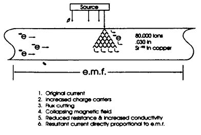
This phenomenon is known as the Beta Voltaic Effect, and it may be explained by referring to Figure 6. For the simple case of this example, we will set the radioactive source (any alpha or beta emitter) external and separate from a silver wire. Now the battery from Figure 5 provides an electromotive force (emf) across the wire and consequently, conduction electrons within the wire are set in uniform motion. By definition, electricity is measured in terms of the number of charged particles (electrons) moving past a point in a unit of time and we call this amperes.
The process by which a beta p[article is absorbed, is such that the beta particle collides with the molecular structure of the copper, knocking electrons free. This electron avalanche occurs until the beta particle (electron) effectively comes to rest. A single beta particle emitted from strontium-90 that is absorbed in copper will generate 80,000 ions in a distance of 0.030 inches. Now, as soon as these electrons are knocked loose, they effectively become free electrons in the wire, and as such these additional electrons are acted upon by the emf applied across the wire to give the avalanche electrons a uniform direction of flow, regardless of their incident angle. This increase in the number of moving charged carriers is measured in the real world as increased current. We also measure a reduction in the resistance of the wire (Ref. 6), an increase in its conductivity (Ref. 7), while the current is directly proportional to the voltage (Ref. 8). In other words, the current goes up with an increase in voltage (Ref. 5). This is basically attributed to the increased emf acting on a greater number of avalanche electrons.
Additionally, flux cutting also occurs as the beta particle approaches the current carrying wire which yields an emf to help drive electrons (Ref. 9).
Figure 7
Now we will look at how we apply this phenomenon to our device. Figure 7 depicts a basic LC tank circuit comprised of an inductor and a capacitor. Theoretically, if this LC circuit were superconductive, then an externally applied electric impulse would yield an LC oscillation that would continue to oscillate forever due to no losses in the system.
However, our LC circuit is not superconductive, and the oscillation damps out due to the losses inherent to the LC tank. To minimize these inherent losses, we tune the circuit into resonance at the self-resonant frequency of the inductor. This causes the inductive and capacitive reactances to cancel, leaving only ohmic losses (resistance).
Figure 8
If we apply a radioactive source as part of the LC tank, then through every cycle of the oscillation of which current is flowing, that current gets amplified by an amount proportional to the activity of the source. All we need is an input of an amount of energy equal to the system losses to achieve a sustained oscillation. At this point, we have a self-driven oscillator that we call a Nuclear Powered Oscillator.
Figure 9
Any energy contributed to this oscillating LC tank must be removed and we accomplish this by simply impedance-matching a transformer which yields high-frequency AC current to drive a load. In a nutshell, that is the principle of operation for the Resonant Nuclear Power Supply: an LC tank circuit oscillating at its self-resonant frequency, driven by natural radioactive decay energy. Energy in excess of the operational requirements is removed through a transformer to yield electrical energy in usable form to drive a load.
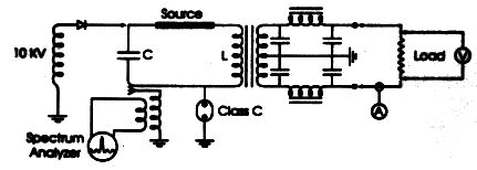
Figure 10
Figure 10 depicts the starting method which involves the use of a high voltage source to charge the capacitor of the tank circuit, which is then discharged to ground through a Class C amplifier at a rate equal to the resonant frequency of the tank circuit. A spectrum analyzer is used to monitor the activity within the tank and once a clean oscillation is started, the high voltage power supply and Class C amplifier are removed, a process that takes a few seconds. Then the power removed from the tank circuit is determined by measuring the voltage drop across a resistor of known value and double-checked by directly measuring the current delivered to the load.
In 1985, a feasibility study was performed including a search of the published literature. This revealed a significant amount of supportive data. Experiments followed on the effects of alpha and beta radiation absorbed in a current-carrying inductor. The results demonstrated (1) a reduction in the resistance of the coil, (2) an increase of the quality factor (Q) of the circuit, and (3) an increased conductivity of the inductor.
A proof of feasibility prototype was built in early 1987, which yielded 75 watts of power. Although the device generated electricity, it also demonstrated a frequency stability problem and showed signs of material degradation.
In mid-1988 a co-development venture was initiated with Atomic Energy of Canada's Radiochemical Company for the purpose of exploring source configuration possibilities in regard to performance and safety parameters.
Our efforts in 1989 primarily centered around optimization of the oscillator, which must be of a design with a high Q, tight coupling, and low loss.
The next 12 slides depict the assembly of the feasibility prototype. Here (Figure 11) we see the strontium-90 foil in the form of an annular cylinder on the right. In the center we see the drum which the foil is to be mounted on, and the cups on the left fit over the ends to hold the coil in place (Figure 12).
Figure 11
Figure 12
Now, the foil is placed on the drum (Figure 13) and the drum with foil is placed in one of the cups (Figure 14) and then the second cup is held in place by a screw (Figure 15).
Figure 13
Figure 14
Figure 15
Next, the source assembly is mounted at the end of a kovar rod electrically insulated from the end housing plate (Figure 16). Here we see the components wired and ready for assembly (Figure 17).
Figure 16
Figure 17
A beryllium-copper foil is mounted on a kovar rod electrically insulated from the other end plate that on assembly is located about the source to slow the primary beta particles and to emit secondary electrons (Figure 18).
Figure 18
Next, the two-layer bare silver ribbon inductor is places about the beryllium-copper to collect the primary beat on the secondary electrons. This is necessary to collect the charges in the high-voltage, high-frequency skin-effect region of the conductor (Figure 19).
Figure 19
Now the composite transformer is placed about the silver inductor which is wired in series with the transformer primary. The transformer is an open-ended flux design of low-damping, high-Q properties, i.e., an oscillation transformer (Figure 20).
Figure 20
Then, with a bit of vacuum grease and an O-ring, the central body is placed over the assembly (Figure 21).
Figure 21
And again, with an O-ring, the other end plate is slid into place (Figure 22). Nuts and bolts keep the assembly together, which is then purged with an inert gas and put on a vacuum pump. We then sweep the spectrum to find the self-resonant frequency and choose an appropriate capacitor to tune the circuit (Figure 23)
Figure 22
Figure 23
This is the actual wiring of the feasibility prototype which operated for a period of time up to 3 weeks.
Some technical problems remain to be solved, like frequency stability and power regulation, while the first commercial application is probably 3 to 5 years away. However, we are continuing the development of the project with increasing support and assistance from both the academic community and the professional commercial community.
Clean air is now a national priority mandating electric vehicle development for use in highly populated areas. By employing suitable radioisotopes, this technology potentially offers a safe, economical alternative to fossil fuel and its related problems.
[References not available]
US Patent # 4,835,433
Apparatus for Direct Conversion of Radioactive Decay Energy to Electrical Energy
(May 30, 1989)Paul M. Brown
Abstract ~ A nuclear battery in which the energy imparted to radioactive decay products during the spontaneous disintegrations of radioactive material is utilized to sustain and amplify the oscillations in a high-Q LC tank circuit is provided. The circuit inductance comprises a coil wound on a core composed of radioactive nuclides connected in series with the primary winding of a power transformer. The core is fabricated from a mixture of three radioactive materials which decay primarily by alpha emission and provides a greater flux of radioactive decay products than the equivalent amount of a single radioactive nuclide.
Inventors: Brown; Paul M. (Boise, ID)
Assignee: Nucell, Inc. (Portland, OR)
Appl. No.: 153070
Filed: February 8, 1988
Current U.S. Class: 310/305; 136/202; 376/320; 976/DIG412
Intern'l Class: G21H 001/00
Field of Search: 376/320,321 310/301,304,305 136/202References Cited
U.S. Patent Documents:
2,548,225, Apr., 1951, Linder (310/304)
2,712,097, Jun., 1955, Auwarter (310/305)
2,739,283, Mar., 1956, Roehrig (310/301)
3,290,522, Dec., 1966, Ginell (310/305)
3,409,820, Nov., 1968, Burke (310/305)
3,530,316, Sep., 1970, Burke (310/301)
3,562,613, Feb., 1971, Adler (310/304)
3,939,366, Feb., 1976, Ato, et al. (310/301)
3,944,438, Mar., 1976, Hursen, et al. (136/202)
4,489,269, Dec., 1984, Edling, et al. (376/320)Primary Examiner: Kyle; Deborah L.; Assistant Examiner: Wasil; Daniel
Attorney, Agent or Firm: Murray; Leslie G.This is a continuation of application Ser. No. 06/855,607, filed Apr. 23, 1986, now abandoned.
Description
Background of the Invention
The present invention relates generally to apparatus for the direct conversion of the energy of radioactive decay products to electrical energy and, more particularly, to the utilization of an alpha source to sustain and amplify oscillations in an LC oscillator circuit.
A growing need exists today for small, compact, reliable, lightweight and self-contained rugged power supplies to provide electrical power in such applications as electric automobiles, homes, industrial, agricultural, recreational, remote monitoring systems and satellites. The majority of today's satellites are powered by solar cells and conventional chemical batteries and require only a small amount of power to operate. Radar, advanced communications satellites and, especially, high-technology weapons platforms will require much larger power sources than today's space power systems can deliver. For the very high power applications, nuclear reactors appear to be the answer. However, for the intermediate power range, 10 to 100 kilowatts (kw), the nuclear reactor presents formidable technical problems. Given today's efficiencies, it would require many acres of solar panels to provide 100 kw. Similarly, enough chemical fuel to provide 100 kw for any significant period of time would be too heavy and bulky for practical use.
Heretofore, there have been known several methods for conversion of radioactive energy released during the decay of natural radioactive elements into electrical energy. A grapefruit-sized radioisotope thermo-electric generator that utilized the heat produced from alpha particles emitted as plutonium-238 decays was developed during the early 1950's. However, the power output was limited to a few hundred watts. Other methods converting the energy of radioactive decay directly into electrical energy are disclosed in US Patent # 3,290,522, # 3,409,820, and # 3,939,366.
US Patent # 3,290,522 entitled "Nuclear Emission Electrical Generator" issued to Robert Ginell on Dec. 6, 1966, discloses apparatus which provides electrical power by modulating the density of a cloud of charged particles confined within an enclosed space by a magnetic field. A radioactive material is positioned at the center of an enclosing hollow sphere having its inner surface coated with silver. The sphere is centrally positioned between the poles of a permanent magnet. The variation in the density of the cloud of charged particles causes a variation in the magnetic field created by the cloud. This variation in the magnetic field cuts an electrically conductive means to create an electrical potential and current therein. The density of the cloud of charged particles may be varied by applying a periodically varying electrostatic or electromagnetic field to the confined cloud of charged particles. The electrical energy is derived from the kinetic energy imparted to the charged particles (decay products) on the occurrence of a spontaneous disintegration event during the decay of the radioactive material. However, with this system, the conversion efficiency is very low and the amount of electrical power provided too small for most applications.
US Patent # 3,409,820 entitled "Electric Power Apparatus" issued to James O. Burke on Nov. 5, 1968, discloses an amplification of an electric current by the conduction of electric current through a radioactive material. While providing some current amplification, the system requires an external power source, such as a conventional battery, and thus, cannot provide sufficient power for most applications.
US Patent # 3,939,366 entitled "Method of Converting Radioactive Energy to Electric Energy and Device for Performing the Same" issued to Yasuro Ato, et al., on Feb. 17, 1976, discloses an apparatus in which radioactive energy is converted to electric energy by irradiating a semiconductor material with radioactive decay products to produce a number of electron-hole pairs in the material. A magnetic field is applied across the semiconductor material in a direction perpendicular to the direction of diffusion of the electron-hole pairs and to the direction of the applied magnetic field thus collecting the electrons and the holes at electrodes provided on the respective end faces of the semiconductor material to produce an electric potential across the semiconductor material. While the conversion efficiency of the system disclosed by Ato, et al., is considerably higher than that disclosed by either Burke or Ginell, the power output of the system is not great enough for applications such as electric automobiles or satellites.
Summary of the Invention
The primary object of the present invention is to provide an apparatus for the direct conversion of the energy of radioactive decay to electric energy.
Another object is to provide an electric power source which is small, compact, reliable, lightweight, self-contained and rugged and therefore adaptable for use in automobiles, homes, industrial, agricultural and recreational applications and satellites.
Still another object is to provide an electric power source capable of providing large amounts of power for long periods of time with little or no maintenance or refueling required.In accordance with the principles of the present invention, a nuclear battery in which the energy imparted to radioactive decay products during the spontaneous disintegrations of radioactive material is utilized to sustain and amplify the oscillations in a high-Q LC tank circuit is provided. The inductance in the tank circuit comprises the primary of a power transformer and is wound about a core composed of a mixture of radioactive materials. A mixture of radioactive materials produces a greater flux of radioactive decay products than the use of a single radioactive material by itself produces thereby providing the necessary flux for large power output from a small core volume. Use of long-lived isotopes, such as radium, ensures that the nuclear battery will have a constant output for at least ten years.
Brief Description of the Drawings
Other and further objects and advantages of the present invention will be apparent from the following detailed description with reference to the accompanying drawings in which
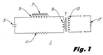
Figure 1 is a schematic diagram of an LC equivalent resonant circuit according to the principles of the present invention;
Figure 2 is a wiring diagram of a nuclear battery constructed according to the principles of the present invention;
Figure 3 is a plan view of the top of the radioactive core of the nuclear battery shown in Figure 2.
Figure 4 is a plan view of the top of the nuclear battery shown in Figure 2; and
Figure 5 is a side view taken along the line A--A of the nuclear battery shown in Figure 3.
Detailed Description of the Preferred Embodiment
Referring now to Figure 1, an equivalent electrical circuit of a nuclear battery constructed according to the principles of the present invention is shown. An LCR circuit 1 is comprised of a capacitor 3, inductor 5, transformer T primary winding 9 and resistance 11 connected in series. It is assumed that the electrical conductors connecting the various circuit elements and forming the inductor 5 and primary winding 9 are perfect conductors; i.e., no DC resistance. Resistor 11 is a lump resistance equivalent to the total DC resistance of the actual circuit components and conductors. The inductor 5 is wound on a core 7 which is composed of a mixture of radioactive elements decaying primarily by alpha particle emission.
When current flows in an electrical circuit energy is dissipated or lost in the form of heat. Thus, when oscillations are induced in an LCR circuit, the oscillations will gradually damp out due to the loss of energy in the circuit unless energy is continuously added to the circuit to sustain the oscillations. In the LCR circuit shown in Figure 1, a portion of the energy imparted to the decay products, such as alpha particles, during the radioactive decay of the materials making up inductor core 7 is introduced into the circuit 1 when the decay products are absorbed by the conductor which forms inductor 5. Once oscillations have been induced in the LCR circuit 1, the energy absorbed by inductor 5 from the radioactive decay of the core 7 materials will sustain the oscillations as long as the amount of energy absorbed is equal to the amount of energy dissipated in the ohmic resistance of the circuit 1. If the absorbed is greater than the amount of energy lost through ohmic heating, the oscillations will be amplified. This excess energy can be delivered to a load 17 connected across the transformer T secondary winding 13.
The processes involved in the conversion of the energy released by the spontaneous disintegration of a radioactive material into electrical energy are numerous and complex. Materials that are naturally radioactive decay by the emission of either an alpha particle or a beta particle, and gamma rays may accompany either process. Radioactive materials that decay primarily by alpha particle emission are preferred as the inductor core 7 material. Alpha particles are emitted with very high speeds, on the order of 1.6.times.10.sup.7 meters per second (m/s), and, consequently, have very high kinetic energy. Alpha particles emitted when radium, for example, decays are found to consist of two groups, those with a kinetic energy of 48.79.times.10.sup.5 electron volts (ev) and those having an energy of 46.95.times.10.sup.5 ev. This kinetic energy must be dissipated when the alpha particles are absorbed by the conductor forming inductor 5. During the absorption process, each alpha particle will collide with one or more atoms in the conductor knocking electrons from their orbits and imparting some kinetic energy to the electrons. This results in increased numbers of conduction electrons in the conductor thereby increasing its conductivity.
Since the alpha particle is a positively charged ion, while the alpha particle is moving it will have an associated magnetic field. When the alpha particle is stopped by the conductor, the magnetic field will collapse thereby inducing a pulse of current in the conductor producing a net increase in the current flowing in the circuit 1. Also, there will be additional electrons stripped from orbit due to ionization produced by the positively charged alpha particles.
Referring now to Figure 2, the nuclear battery 20 is constructed in a cylindrical configuration. Inductor 5 is constructed of copper wire wound in a single layer around the radioactive core 7. Decay products, such as alpha particles, are emitted radially outward from the core 7 as indicated by arrows 2 to be absorbed by the copper conductor forming inductor 5. Eight transformers 15 are arranged in a circular pattern to form a cylinder concentric with and surrounding inductor 5. The transformers 15 have primary windings 9a-9h connected in series which are then connected in series with inductor 5 and capacitor 3 to form an LCR circuit. The central core 7, inductor 5 and the eight transformers 15 are positioned within a cylindrical-shaped container 19. Copper wire is wound in a single layer on the outside wall and the inside wall of cylinder 19 to form windings 23 and 21 respectively. The transformers 15 secondary windings 13a-13h and windings 21 and 23 are connected in series to output terminals 25 and 27. The configuration of inductor 5 is designed to insure maximum irradiation of the copper conductor by the radioactive core source 7. The cylindrical configuration of the power transformer insures maximum transformer efficiency with minimum magnetic flux leakage.
Referring now to Figure 3, the radioactive core 7 comprises a radium needle 39 surrounded by a cylinder of powdered thorium 31 having a plurality of uranium rods 33 positioned within the thorium 31. The powdered thorium 31 is contained by concentric cylinder walls 35 and 37. The use of a mixture of these radioactive materials for the core 7 produces a synergistic effect in that a greater flux of alpha particles is produced than by any one of the materials above due to additional induced disintegration events occurring.
Referring now to Figures 4 and 5, top and side views of a nuclear battery constructed in accordance with the principles of the present invention is shown. The inductor core 7 consists of radium needle 39 positioned longitudinally in the center of a cylinder of powdered thorium 31. The powdered thorium 31 is contained by concentric cylinder walls 35 and 37 (a material such as light cardboard may be utilized for this purpose). Inductor 5 is formed from two layers of American Wire Gage (AWG) #8 copper wire, one layer 41 wound on the inward facing wall 37 surrounding the radium needle 39 and the other layer 43 wound on the outside of wall 35 thereby surrounding the powdered thorium 31 and uranium rods 33. The inductor core 7 is 11/4 inches in diameter and 6 inches long, with an overall diameter of 15/8 inches for inductor 5. The eight transformers 15 each have a core 45 of laminated silicon steel 3/4 inches square by 6 inches in length. The primary windings 9a-9h each consist of four layers of AWG #18 copper wire and the secondary windings 13a-13h each consist of two layers of AWG #12 copper wire. The transformers 15 have an overall outside diameter of 11/4 inches. The outer cylinder 19 is laminated silicon steel and an inner winding 21 of AWG #12 copper wire and an outer winding 23 of AWG #12 copper wire. End plates 47 and 49 consisting of 1/2 inch thick annular rings of laminated silicon steel having an inner diameter of 23/4 inches and outer diameter of 43/4 inches are utilized to provide a low reluctance path to complete the magnetic circuit as shown by dashed line 51.
When assembled, the nuclear battery is immersed in an oil-filled can (not shown) equipped with heat sinks (not shown) to provide the necessary cooling for the power transformer. The capacitor 3 used in the LCR circuit is a high Q energy discharge resonant capacitor of the oil filled type.
Using a one millicurie radium needle 39, 200 grams of uranium 33 and 100 grams of powdered thorium 31 in the configuration shown in Figures 2 and 3, at 86 kiloHz, a continuous output of 23 amperes at 400 volts into a resistance load has been achieved. A configuration utilizing additional radium needles 53, as shown in FIG. 4, may be used to achieve higher power outputs.
While I have shown and described the preferred embodiment of my invention, it will be apparent to those skilled in the art that this invention is not limited to the specific structure described herein and that numerous changes and variations may be made therein without departing from the spirit of the invention or exceeding the scope of the appended claims.
Claims
I claim:
1. Apparatus for converting radioactive energy to electrical energy, said apparatus comprising:
an electrical conductor wound on a core to form an inductor having a first inductance, said core being of radioactive material;a capacitor having a predetermined capacitance C;
a transformer having a primary winding, a secondary winding and a transformer core, said primary winding and said secondary winding wound on said transformer core, said primary winding having a second inductance, said secondary winding for coupling electrical energy to a workload; and
electrical conductor means for connecting said inductor, said capacitor and said primary winding in series fashion to form a series LCR circuit wherein electrical oscillations are induced, said electrical oscillations being sustained and amplified by the energy transferred to said electrical conductor by the radioactive decay of said radioactive material, wherein L is the sum of said first inductance and said second inductance and R is a predetermined resistance.
2. Apparatus as in claim 1 wherein said core is comprised of at least two different radioactive materials.
3. Apparatus as in claim 2 wherein said radioactive materials decay primarily by alpha particle emission.
4. Apparatus as in claim 3 wherein said core is comprised of three radioactive materials.
5. Apparatus as in claim 4 wherein said three radioactive materials comprise radium, uranium and thorium.
6. Apparatus for converting the energy of radioactive decay products to electrical energy, said apparatus comprising:
an electrical conductor wound on a core to form an inductor having a first inductance, said core being fabricated of radioactive material;
a capacitor having a predetermined capacitance C;
a plurality of transformers disposed in a generally circular configuration to form a cylinder, said core being disposed within said cylinder, the longitudinal axis of said core being coincident with the longitudinal axis of said cylinder, each of said plurality of transformers having a primary winding and a secondary winding, each of said plurality of primary windings connected in series fashion with the remaining primary windings, each of said plurality of secondary windings connected in series fashion with the remaining secondary windings, said series-connected secondary windings for coupling electrical energy to a workload; and
electrical conductor means for connecting said inductor, said capacitor, said series-connected primary windings and a predetermined resistance R in a series fashion to form a series LCR circuit wherein electrical oscillations are induced, said electrical oscillations being sustained and amplified by the energy transferred to said electrical conductor by the radioactive decay of said radioactive material.
7. Apparatus as in claim 6 wherein said core is comprised of at least two different radioactive materials.
8. Apparatus as in claim 7 wherein said series LCR circuit comprises an inductance L equivalent to the sum of the inductances of said inductor and said series-connected primary windings, capacitance C and a resistance R equal to the total distributed DC resistance of said LCR circuit.
9. Apparatus as in claim 8 further including an outer cylinder enclosing said cylinder and having its longitudinal axis coincident with the longitudinal axis of said core, an inner winding disposed adjacent the inner surface of said outer cylinder, an outer winding wound on the outer surface of said outer cylinder, said inner and outer windings connected in series fashion with said series-connected secondary windings for coupling electrical energy to a workload.
10. Apparatus as in claim 9 wherein said core is comprised of a mixture of radium, uranium, and thorium.
Nuclear Solutions, Inc. regretfully announces the death of Dr. Paul M. Brown. Dr. Brown was killed on April 7, 2002 in an automobile accident in Boise, Idaho. He developed the idea for the Company's patented photoremediation technology for the remediation of nuclear waste that will now be his legacy. He is survived by his wife and two children. ``Our team is saddened by this tragic loss, however, we remain fully committed to realizing the vision that Dr. Brown inspired us with. His vision holds the promise of safe and economical treatment of nuclear waste and the potential for a new generation of power reactors,'' said John Dempsey, Executive Vice President and Chief Operating Officer. ``We have assembled a management and scientific team that is competent and fully capable of implementing the technology that Dr. Brown invented as well as our newer acquisitions such as our GHR tritium removal technology,'' he concluded. John Dempsey and Patrick Herda, co-founder and Vice President of Business Development will direct the company's activities until a new CEO is appointed by the company's board of directors. Their efforts will be supported by Dr. Qi Ao, Vice President of Research and Development and Adrian Joseph, PhD., Vice President of Special Projects. 1. The application of photonuclear physics to nuclear waste is called Photodeactivation. Photodeactivation involves the irradiation of specific radioactive isotopes to force the emission of a neutron, thereby producing an isotope of reduced atomic mass. These resultant isotopes can be characteristically either not radioactive or radioactive with a short half-life. The fundamental mechanism works on the laboratory scale, and preliminary research suggests that this technology will also work on the industrial scale. NSOL is taking the steps necessary for commercialization of the technology. As for most of the advanced nuclear technologies developed today, computer simulation is one of the most important and necessary steps. NSOL will use and improve a series of nuclear simulation codes. The new set of simulation codes will allow the NSOL research and development team to design, test, improve, and develop experiments and commercial facilities through computer modeling. NSOL plans to capitalize on its patent and patent-pending technology by forming strategic alliances and joint ventures with well-established leaders in the nuclear industry. Continued revenue streams are expected through licensing of the technology with both upfront fees and ongoing royalties. 2. NSOL's technology, the HYPERCON(TM) ADS process, is an X-ray based photodisintegration process. The technology could be developed into new applications for remediation of nuclear waste. The proposed process would operate at a sub-critical level, and be inherently safe. Any excess heat produced by the process could also be recovered to generate electricity. 3. NSOL holds a licencefor the exclusive worldwide rights to a proprietary technology for the removal of radioactive isotopes from contaminated wastewater called GHR. Water containing ritium and deuterium is currently stored in several locations worldwide due to the expense of available methods of treatment. Severe health problems for humans and animals are linked to these contaminants and pose a worldwide environmental threat. Several methods for the extraction of tritium from water are currently available. However these methods such as chemical, electrolytic, ion exchange, or distillation systems have high costs associated with their operation. As a result significant quantities of tritium-contaminated water are being stored rather than treated due to cost concerns. The storage of tritium-contaminated water poses a risk to the environment due to the high mobility of water after a containment failure.
USP Application # 2002169351Remediation of Radioactive Waste by Stimulated Radioactive Decay
( 11-14-2002 )
Paul M. Brown
Classification: - international: G21F9/00; G21G1/12; G21F9/00; G21G1/00; (IPC1-7): G21F9/00; - european: G21G1/12
Application number: US20010877624 20010608
Priority number(s): US20010877624 20010608; US19980105313 19980626Abstract ~ Disclosed is a radioactive waste treatment process for transmuting long-lived radioisotopes into short-lived radioisotopes through applied nuclear physics. Nuclear reactions, specifically of the (gamma, n) type, also known as photodisintegration, are utilized to accomplish this transmutation from troublesome, long-lived radioactive waste isotope(s) of given atomic mass to shorter-lived or stable materials of lower atomic mass, by exposing the troublesome isotopes to a high energy photon flux for a sustained time. Generally speaking, the target nucleus of the radioisotope(s) to be treated is irradiated by gamma photons of an energy greater than the binding energy of the neutron in the target nucleus. This causes the irradiated nucleus to absorb the gamma rays, thereby placing the nucleus in an excited state. Upon relaxation, the nucleus ejects a neutron through the (gamma, n) reaction, thereby transmuting the element to an isotope of lower atomic mass and shorter half-life.