Contact : Stan Widows
Inventive Research
Div. S.R. Widows Co. Inc.
800-357-6290
Jason Oliver &
AC
Solar Generator
Inventive Research, a Division
of S. R. Widows Company, Inc., of Indiana, has patented a way to
generate AC power directly from a solar panel. Why is this so
important? It makes it possible to simply hook the solar panels
directly into the power grid without the need for expensive DC to AC
power conversion equipment. This invention, when commercialized, will
make the cost of solar power more practical and affordable.
We’ve heard about the promise of cheap solar energy now for decades.
You’d think by now that at least in the world’s sunniest areas all the
cities would be supplementing their power with clean renewable solar
power. Sadly this is not the case.
Here’s the problem. Solar panels today produce DC power which has to be
converted to AC to be used by by most homes and businesses. The price
of solar panels combined with the price of inverters, phase
synchronizers, installation and maintenance has made the price of solar
prohibitive. Add to that the loss of power from the different
components used in the DC to AC conversion process and it becomes even
more unattractive. But what if there was a better way?
Nearly a century ago a battle between two of America’s most influential
inventors decided the power we use today. Thomas Edison’s inventions
generated and utilized DC power and Nikola Tesla’s inventions used his
newly discovered AC power. Tesla’s AC eventually won out because it
could be transfered over long distances more efficiently.
Jason Oliver, lead inventor for
Inventive Research is not the typical researcher; he’s an automotive
master mechanic from Indiana who more than a decade ago developed a
passion for the inventions of Tesla. He looked for clues from how power
is generated today to come up with their newest invention, the AC
generating solar panel.
Today AC power is produced for the power grid by AC generators. The
generators are powered by mechanical energy provided by water turbines
(hydro-electric) or steam turbines powered from coal, natural gas or
nuclear fuel. The mechanical energy rotates the coils of the generator
in a magnetic field to produce voltage. Because the conductor coil of
the generator flips direction during rotation in the magnetic field the
resulting voltage produced is sinusoidal or AC.
Inventive Research replicated this sinusoidal voltage by mechanically
manipulating alternate banks of solar cells to turn off and on. They
spent many years years developing this technology. They call it the AC
Solar Generator. It’s so simple and practical you won’t believe it
hasn’t been done before, but it hasn’t. Inventive Research and their
attorneys did an exhaustive patent search to make sure of that.
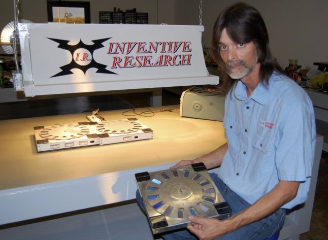
The process Inventive Research used to do this is simple but pure
genius in its application. Jason arranged modified standard solar cells
into a circular pattern mounted on a base.
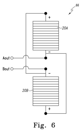
Half of the cells are wired in one circuit and half in another circuit
Mounted above the solar cells is a spinning disk powered by a DC
electric motor. The DC motor gets its power from four small DC solar
cells mounted in the corners of the base. The disk has portals cut into
it allowing light to pass through to every other solar cell below it.
As the disk spins each of the banks of solar cells is alternately
exposed to light and alternately produce power. When the portal is half
way between the two cells the voltage cancels and drops to zero. The
resulting voltage is sinusoidal or AC. It can even be configured to
produce three phase AC power...
Combining the phase matching with the alternating current generation is
what allows the AC solar generator to create AC power without the
losses and cost associated with the AC to DC power conversion process.
Other benfits include:
• Generates free energy from the sun
• Non-polluting energy reduces emissions: Has no direct impact on the
environment
• It’s easily scalable
• Grid-Tie systems allow you to sell excess electricity back to the
utility
• Can be installed and operated anywhere including areas of difficult
access and remote locations
• Helps get us off dependence on foreign oil
• PV cells make no noise and give off no exhaust
This is truly a transforming technology. The AC solar generator has the
potential to reduce the use of fossil fuels tremendously if you just
imagine them installed photovoltaic solar power centers around the
country generating supplemental power for the grid.
Inventive Research is expecting to receive the final patents later this
year. If you are interested in licensing or purchasing the patents for
this technology you can contact Stan Widows at Inventive Research a
division of S.R. Widows Co. Inc. at 800-357-6290
Inventor: OLIVER JASON ALLEN
EC: IPC: H01L25/00; H01L25/00
Abstract -- A device, system
and method for generating alternating current (a/c) electricity
directly from photovoltaic cells utilize an array of photovoltaic cell
pairs that are each connected in anti-parallel to form an a/c junction.
The system, device and method mechanically gradually exposes and shades
photovoltaic cell pairs to sunlight to generate alternating current
electricity at an a/c junction of the solar cell pairs. Gradually and
alternately exposing and shading the two anti-parallel connected solar
cells of each solar cell pair causes the amplitude and polarity of the
electricity at the a/c junction to gradually rise and fall to produce
alternating current electricity. The gradual, alternating exposure and
shading of the two anti-parallel solar cells is accomplished by
mechanically covering and exposing the solar cell pairs. This is
efficiently accomplished by a rotating segmented disc positioned over
an array of solar cell pairs.
Description
BACKGROUND OF THE INVENTION
Field of the Invention
The present invention relates to photovoltaics (i.e. technology and
research related to the application of photovoltaic cells in producing
electricity for practical use) and, more particularly, to devices,
systems and methods for generating alternating current electricity from
photovoltaic cells.
Background Information
The demand and need for clean and renewable energy is becoming more
urgent as earth undergoes global climate changes. Generation of
electricity from coal produces over 50% of the carbon dioxide released
into the atmosphere each year. Coal and other fossil fuels will also
eventually run out. The hydroelectric power generation of electricity
is limited to places where there is an adequate water source. Nuclear
energy for the creation of electricity has the drawback of creating
nuclear waste. However, one type of clean renewable energy is solar
energy or sunlight. Solar energy is a constant source of clean energy
that can shine on all areas of the surface of the planet. Solar energy
or sunlight can be converted into electricity by a photovoltaic cell. A
photovoltaic cell known as a solar cell captures and converts sunlight
into electricity. A solar cell is made from a semiconducting material
(a semiconductor) such as silicon that absorbs the sunlight which
generates a flow of electricity through the solar cell. Because of the
properties of semiconductors, positive and negative terminals of the
solar cell are static and electron flow from a solar cell is
uni-directional (i.e. the electricity can only flow in one direction).
Thus, as with all photovoltaic cells, the solar cell produces only
direct current (d/c) electricity. The problem with direct current
electricity is that direct current electricity is difficult to transmit
any appreciable distance, which limits its use. Thus, alternating
current electricity is more usable than direct current electricity.
Moreover, most electrical devices utilize alternating current (a/c)
electricity.
Various prior art devices have attempted to provide suitable
alternating current electricity from photovoltaic or solar cells. For
instance, U.S. Patent No. 4,075,034 issued to Butler on February 21 ,
1978 (hereinafter, "Butler") provides a solar converter for producing
variable amplitude alternating current waveforms directly from solar
energy by using a photo-voltaic cell bank array formed of a plurality
of weighted photo-voltaic segments. A multi-sided high speed, rotating
and light concentrating concave mirror system provides light on and
past the weighted segments of the photo-voltaic bank to produce
instantaneous output which are proportional to the number of cells
scanned in each segment. A simulated alternating current (a/c) waveform
is produced by suitable arrangement of the photo-voltaic segments. The
simulated a/c waveform of Butler and its fragile manner (glass mirrors)
of producing the simulated a/c waveform by the high speed rotating
mirror is not efficient. Moreover, Butler is not easily scalable to
produce larger voltages/amperes nor is it relatively maintenance free.
In U.S. Patent Publication No. 2005/0034750 by Rabinowitz published
February 17, 2005 (hereinafter, "Rabinowitz"), a solar cell alternating
current generator is provided that uses a dynamic spinning ensemble of
mini-mirrors to both concentrate and modulate rays from the sun onto a
photovoltaic collector array. The focusing and superimposed spinning
action produces single phase and multiphase alternating current
electricity. The problem with Rabinowitz is again, the use of glass
mirrors, the need for focusing the mini-mirrors and maintain their high
speed spinning is not efficient.
In U.S. Patent No. 6,774,299 issued to Ford on August 10, 2004
(hereinafter, "Ford"), a solar alternating current electricity
generator is provided that utilizes a rotating, partitioned array of
photovoltaic cells. Contact brushes and wiring are provided to transfer
the electric current to an applied load. The drawback to Ford is the
need for contact brushes and wiring to generate the alternating current
electricity. Moreover, the rotating photovoltaic cell vanes of Ford are
not efficient.
In U.S. Patent No. 4,728,878 issued to Anthony on March 1 , 1988
(hereinafter, "Anthony"), a solar energy electric generating system is
provided for space vehicles which directly generates alternating
current from ambient light without power conversion. Light incident to
photocell arrays is mechanically or electrically gated to produce
fluctuating direct current (d/c) electricity. A number of transforming
devices are provided to convert the fluctuating d/c current to
alternating current (a/c). Through variation of the frequency and duty
cycle of the pulsing output voltage, frequency and phase relative to a
reference may be controlled. However, with the Anthony solar energy
electric generating system, the mechanical gating provides a square
wave that is then conditioned to provide an alternating current
waveform.
Last, in U.S. Patent No. 4,577,052 issued to Schutten et al. on Mach
18, 1986 (hereinafter, "Schutten"), an alternating current solar cell
is provided by connecting solar cells (P/N junctions) in anti-parallel
between a pair of main terminals. Light is provided alternately on the
P/N junctions through a mirror system that splits the beam and causes
the split beam to impinge on the P/N junctions.
It is clear from the above that the prior art devices for generating
alternating current electricity directly from photovoltaic or solar
cells are complicated, difficult to align and maintain, and cannot
provide adequate scaling for small and large a/c current production.
In view of the above, it is desirable to have a solar powered
alternating current (a/c) electricity generator, system and method that
produces single or multi-phase a/c electricity that is simple,
efficient and easily scalable in voltage and/or amperage.
SUMMARY OF THE INVENTION
The present invention is a system, device and method for directly
generating alternating current electricity from photovoltaic cells. The
system, device and method mechanically gradually exposes and shades
photovoltaic cell pairs connected in anti-parallel to sunlight to
generate alternating current electricity at an a/c junction of the
solar cell pairs. Gradually and alternately exposing and shading the
two anti-parallel connected solar cells of each solar cell pair causes
the amplitude and polarity of the electricity at the a/c junction to
gradually rise and fall to produce alternating current electricity. The
gradual, alternating exposure and shading of the two anti-parallel
solar cells is accomplished by mechanically covering and exposing the
solar cell pairs.
In particular, while one solar cell of an anti-parallel connected solar
cell pair undergoes gradual exposure to sunlight from 0% exposure (100%
shaded) of the solar cell electricity generating area to 100% exposure
(0% shaded) of the solar cell electricity generating area, the other
solar cell of the solar cell pair undergoes gradual shading from
sunlight from 0% shaded (100% exposure) to 100% shaded (0% exposure).
Such gradual, alternating exposure and covering of each solar cell of
each anti-parallel connected solar cell pair is periodic. The rate of
exposure and shading determines frequency.
In one form, a rotating disc situated over the solar cell pairs has
spaced apart openings forming coverings between each opening to
alternately expose and shade the solar cell pairs during rotation. A
direct current motor is utilized to rotate the segmented disc. The
motor is preferably powered by separate solar cells.
The present invention also provides a phase synchronizer for
maintaining a desired alternating current frequency. The phase
synchronizer controls the motor to control rotation of the segmented
disc.
The present invention makes solar energy a viable, cost effective,
environmentally friendly option for residential and/or commercial use.
The present invention is capable of being used on a minute, small or
large scale through appropriate scaling the solar cell a/c electricity
generator and/or the use of a plurality thereof. Solar cell a/c
electricity generator arrays can easily produce the power equivalent to
an average power plant today, while being environmentally friendly
enough to be located proximate a playground, school or in any urban
environment. Large scale solar cell a/c electricity generator arrays
can be easily set up even in the most remote places in the world. The
present invention reduces the need of other forms of power. Moreover,
the present solar cell a/c electricity generator can be set up and used
anywhere.
It is thus an object of the present invention to produce alternating
current electricity of specific frequencies, single or three phase,
from solar cells in a cost efficient and simple manner.
BRIEF DESCRIPTION OF THE DRAWINGS
The above mentioned and other features, advantages and objects of this
invention, and the manner of attaining them, will become apparent and
the invention itself will be better understood by reference to the
following description of an embodiment of the invention taken in
conjunction with the accompanying drawings, wherein:
Fig. 1 is a perspective view of
a photovoltaic alternating current
(a/c) electricity generator fashioned in accordance with the principles
of the present invention;
Fig. 2 is a lower perspective
view of the photovoltaic a/c electricity
generator of Fig. 1 taken from another side of the generator;
Fig. 3 is a perspective view of
the photovoltaic a/c electricity
generator of Fig. 1 with the rotating disk thereof removed;
Fig. 4 is a perspective view of the rotating disk of the
photovoltaic
a/c electricity generator of Fig. 1 ;
Fig. 5 is a schematic view of
the underside connections of the
photovoltaic a/c electricity generator of Fig. 1 ;
Fig. 6 is a diagram illustrating the anti-parallel connection of
a
photovoltaic cell pair as used in the photovoltaic a/c electricity
generator of Fig. 1 ;
Fig. 7 is a diagram illustrating the parallel connection of an
exemplary photovoltaic cell pair array as may be used in the
photovoltaic a/c electricity generator of Fig. 1 ;
Fig. 8A is a first diagram in a sequence of representative
diagrams
illustrating the manner of generating a/c electricity from a
photovoltaic cell pair of a photovoltaic cell pair array of the
photovoltaic a/c electricity generator of Fig. 1 ;
Fig. 8B is a second diagram in the sequence of representative
diagrams
illustrating the manner of generating a/c electricity from a
photovoltaic cell pair of a photovoltaic cell pair array of the
photovoltaic a/c electricity generator of Fig. 1 ; Fig. 8C is a third
diagram in the sequence of representative diagrams illustrating the
manner of generating a/c electricity from a photovoltaic cell pair of a
photovoltaic cell pair array of the photovoltaic a/c electricity
generator of Fig. 1 ;
Fig. 8D is a fourth diagram in the sequence of representative
diagrams
illustrating the manner of generating a/c electricity from a
photovoltaic cell pair of a photovoltaic cell pair array of the
photovoltaic a/c electricity generator of Fig. 1 ;
Fig. 8E is a fifth diagram in the sequence of representative
diagrams
illustrating the manner of generating a/c electricity from a
photovoltaic cell pair of a photovoltaic cell pair array of the
photovoltaic a/c electricity generator of Fig. 1 ;
Fig. 9 is a schematic diagram of an exemplary phase synchronizer
as
used in the photovoltaic a/c electricity generator of Fig. 1 ; and
Fig. 10 is a flow chart illustrating a logic diagram of an
exemplary
embodiment of the phase synchronizer of the photovoltaic a/c
electricity generator of Fig. 1.
Like reference numerals indicate the same or similar parts throughout
the several figures.
A description of the features, functions and/or configuration of the
components depicted in the various figures will now be presented. It
should be appreciated that not all of the features of the components of
the figures are necessarily described. Some of these non discussed
features as well as discussed features are inherent from the figures.
Other non discussed features may be inherent in component geometry
and/or configuration.
DETAILED DESCRIPTION OF AN EMBODIMENT
OF THE INVENTION
Referring to Figs. 1-5, there is depicted various views of an exemplary
embodiment of a photovoltaic alternating current (a/c) electricity
generator, generally designated 10, fashioned in accordance with the
present principles. The photovoltaic a/c generator 10 is embodied as a
solar cell a/c electricity generator 10, but it should be appreciated
that a photovoltaic a/c electricity generator fashioned in accordance
with the present principles may use photovoltaic cells other than solar
cells.
The solar cell a/c electricity generator 10 has a base, frame or other
mounting structure 12 ("base 12") that supports the various components
thereof. The base 12 may be formed of wood, plastic or other suitable
material which is preferably, but not necessarily, a non conducting
material. It should be understood that while the base 12 is shown as a
box or a box-like structure, the base may be a substrate, board or
other suitable mounting or supporting structure. The base 12 includes
an alternating current (a/c) electricity production portion 14 formed
by a disk 15 and a plurality of photovoltaic or solar cells 20
(hereinafter, "solar cells 20"). As best seen in Fig. 3, the plurality
of solar cells 20 is arranged in a generally circular array 21 on an
upper surface 13 of the base 12. It should be appreciated that arrays
other than circular may be used within the present principles. It
should also be appreciated that while the solar cells 20 are shown as
rectangles, the size and shape of the solar cells 20 may be otherwise,
such as truncated conical, triangular, polygonal or square.
As best seen in Fig. 4, the disc 15 has a generally flat body made of a
sunlight blocking material that is generally the circumference of the
solar cell array 21 in order to extend over the solar cell array 21
when in use (see, e.g., Figs. 1 and 2). The disc 15 is also preferably
made of a lightweight material that resists warping or is not
susceptible to warping. The disc 15 is preferably reflective either
inherently or via a coating, film, overlay or the like. It should be
appreciated that the disc 15 may be partially reflective or
non-reflective if desired. The disc 15 has a plurality of cutouts,
openings, windows or the like 16 ("cutouts 16") formed thereabout. The
size and shape of the cutouts 16 generally correspond to the size and
shape of the solar cells 20 and particularly is sized and shaped to
allow total exposure of a solar cell 20 to sunlight when the cutout 16
is positioned over the solar cell 20. The cutouts 16 are situated and
spaced on the disc 15 so as to define a plurality of covers, coverings,
blocks or the like 18 ("coverings 18"). The coverings 18 are sized and
shaped to completely cover or block a solar cell 20 when the covering
is over the solar cell 20.
The cutouts 16 and coverings 18 are alternately radially situated about
the disc 15. The number of cutouts 16 corresponds by 1 /2 to the number
of solar cells 20 so that the number of coverings 18 corresponds by 1/2
to the number of solar cells 20. Therefore, when the disc 15 is
situated on frame 12 and over the solar cell array 21 , the cutouts 16
and coverings 18 expose 1/2 of the total solar cell array area and
cover 1/2 of the total solar cell array area. As the disc 15 rotates
over the array 21 of solar cells 20, the cutouts 16 and coverings 18
continuously gradually expose and cover the array of solar cells.
The disc 15 is rotated over the solar cell array 21 by a direct current
motor 26 (see, e.g., Fig. 3) that is supported by the base 12. Rotation
may be either clockwise or counterclockwise. A counterclockwise
rotation of the disc 15 is represented in the figures by the curved
arrow(s). The motor 26 is coupled to a phase synchronizer 40 via a
motor connection 44 (see Fig. 5). The phase synchronizer 40 provides
control/control signals to the motor 26 for varying the rotational
speed of the disc 15. Rotational speed of the disc 15 determines the
frequency of resultant alternating current(s) from the solar cell a/c
electricity generator 10. Additionally, the phase synchronizer 40
determines phase of the resultant a/c electricity relative to a
predetermined phase or phase value (e.g. 60Hz) and causes the motor 26
to speed up or slow down if necessary. The motor 26 is powered by
photovoltaic (solar) cells 22 that are situated on the base 12 so as to
be continuously exposed to any sunlight. As best depicted in Fig. 5,
the solar cells 22 are connected via connectors 23 to provide the
proper voltage and amperage to the motor 26 and motor controller of the
phase synchronizer 40) for properly operating the motor 26 for rotation
of the disc 15. If desired, rechargeable batteries 28 may be connected
to the phase synchronizer 40 that charge with energy from the solar
cells 22 and provide startup energy for the motor 26.
The solar cell a/c electricity generator 10 may include a power on/off
switch 11 for making the solar cell a/c electricity generator 10
operable or not operable. Alternately, or in addition, the solar cell
a/c electricity generator 10 may include a light sensor 42 (shown in
Fig. 5) that senses when sunlight is present to then turn on the solar
cell a/c electricity generator 10. Other configurations may be used.
As can be discerned from Figs. 1 and 2, rotation of the disc 15 causes
the cutouts 16 and coverings 18 to alternately expose and cover
adjacent solar cells 20. The faster that the solar cells 20 are exposed
and covered (rotation speed of the disc 15), the higher the frequency
of a/c electricity produced. The slower that the solar cells 20 are
exposed and covered (rotation speed of the disc 15), the lower the
frequency of the a/c electricity produced. Since the solar cells are
wired in anti-parallel, an alternating current is generated between the
a/c junction of the solar cell pairs as the solar cell pairs are
alternately, gradually exposed and covered. Alternately stated, the
total solar cell area of a solar cell pair comprises 100% where one
solar cell of the solar cell pair defines 50% of the total area and the
other solar cell of the solar cell pair defines the other 50% of the
total area. The one solar cell of an anti-parallel connected solar cell
pair undergoes gradual exposure to sunlight from 0% exposure (100%
shaded) of the solar cell electricity generating area to 100% exposure
(0% shaded) of the solar cell electricity generating area, the other
solar cell of the solar cell pair undergoes gradual shading from
sunlight from 0% shaded (100% exposure) to 100% shaded (0% exposure).
Such gradual, alternating exposure and covering of each solar cell of
each anti-parallel connected solar cell pair is periodic.
This periodic sequence is illustrated in Figs. 8A through 8E. Figs. 8A
through 8E are a representation of the manner in which two solar cells
of a solar cell pair are alternately, gradually exposed and covered to
produce an a/c waveform. The principles of the present invention are
applicable to any connection configuration of solar cell pairs, whether
opposite one another as in Figs. 8A through 8E, or adjacent one another
as in Fig. 3.
Fig. 8A is an arbitrary beginning to the sequence wherein there is
represented a negative current at the output terminals Aout and Bout of
the solar cell pair, at its peak negative amplitude. In Fig. 8A, solar
cell 2OB of a solar cell pair is 100% exposed (0% covered) while solar
cell 2OA is 0% exposed (100% covered). Particularly, a cutout 16 is
fully over the solar cell 2OB thus fully exposing solar cell 2OB, while
at the same time, a covering 18 is fully over the solar cell 2OA thus
fully shading (covering or blocking) the solar cell 2OA. A peak
negative current is thus provided at output terminals Aout and Bout
which is shown on the graph of Fig. 8A as current point isA- In Fig. 8B
of the sequence, the rotating disc 15 has moved slightly
counterclockwise such that the opening 16 that was totally exposing the
solar cell 2OB is now exposing only 1/2 (and/or covering 1/2) of the
area of the solar cell 2OB, while the covering 18 that was totally
shading the solar cell 2OA is now covering only 1/2 (and/or exposing
1/2) of the area of the solar cell 2OA. This results in a zero (0)
current at the output terminals Aout and Bout as shown on the graph of
Fig. 8B as current point isB- It should be appreciated that the
rotational movement of the disc 15 from point shown in Fig. 8A to that
shown in Fig. 8B gradually exposes and covers the solar cells, as
described above, to create the gradual and not stepped a/c waveform as
depicted in the graph of Fig. 8B.
In Fig. 8C of the sequence, the rotating disc 15 has moved further
slightly counterclockwise. In Fig. 8C, solar cell 2OA of a solar cell
pair is now 100% exposed (0% covered) while solar cell 2OB is now 0%
exposed (100% covered). A cutout 16 is fully over the solar cell 2OA
thus fully exposing solar cell 2OA, while at the same time, a covering
18 is fully over the solar cell 2OB thus fully shading (covering or
blocking) the solar cell 2OB. A peak positive current is thus provided
at output terminals Aout and B0Ut which is shown on the graph of Fig.
8A as current point i8C. Again, it should be appreciated that the
rotational movement of the disc 15 from point shown in Fig. 8B to that
shown in Fig. 8C gradually exposes and covers the solar cells, as
described above, to create the gradual and not stepped a/c waveform as
depicted in the graph of Fig. 8C.
In Fig. 8D of the sequence, the rotating disc 15 has moved further
slightly counterclockwise such that the opening 16 that was totally
exposing the solar cell 2OA is now exposing only 1/2 (and/or covering
1/2) of the area of the solar cell 2OA, while the covering 18 that was
totally shading the solar cell 2OB is now covering only 1/2 (and/or
exposing 1/2) of the area of the solar cell 2OB. While opposite to that
of Fig. 8B, this results in a zero (0) current at the output terminals
Aout and Bout as shown on the graph of Fig. 8D as current point i8D.
Again, it should be appreciated that the rotational movement of the
disc 15 from point shown in Fig. 8C to that shown in Fig. 8D gradually
exposes and covers the solar cells, as described above, to create the
gradual and not stepped a/c waveform as depicted in the graph of Fig.
8D.
Lastly, in Fig. 8E of the sequence, the disk has moved further
counterclockwise such that a cutout 16 has moved fully over solar cell
2OB such that solar cell 2OB is again 100% exposed (0% covered) while a
covering 18 has again moved fully over the solar cell 2OA such that the
solar cell 2OA is 0% exposed (100% covered). Particularly, the cutout
16 is fully over the solar cell 2OB thus fully exposing solar cell 2OB,
while at the same time, a covering 18 is fully over the solar cell 2OA
thus fully shading (covering or blocking) the solar cell 2OA. A peak
negative current is thus again provided at output terminals Aout and
Bout which is shown on the graph of Fig. 8E as current point i8E-
Again, it should be appreciated that the rotational movement of the
disc 15 from point shown in Fig. 8D to that shown in Fig. 8E gradually
exposes and covers the solar cells, as described above, to create the
gradual and not stepped a/c waveform as depicted in the graph of Fig.
8E. Fig. 8E completes a full cycle of the a/c waveform.
Referring back to Fig. 3, the total number of solar cells 20 must be an
even number since two solar cells 20 are utilized to provide a solar
cell pair having a single a/c junction. Multiple solar cell pairs are
connected together to increase the voltage or amperage depending on the
connection. Connection of all of the solar cell pairs of the array 21
produces a single phase a/c waveform. The solar cell pairs may use
three connected banks of solar cells pairs to achieve a three-phase a/c
waveform. In Fig. 3, since the total number of solar cell pairs is
fifteen (15) they all can be connected to form a single phase a/c
waveform, or they can be divided into three (3) banks of five (5) solar
cell pairs each to achieve a three-phase a/c/ waveform.
Referring additionally to Fig. 6, a solar cell pair 66 of solar cells
2OA and 2OB is shown. As can be seen, the solar cell pair 66 is
connected in anti-parallel to provide an a/c junction (i.e. two a/c
output terminals Aout and Bout)- Particularly, the positive terminal of
the solar cell 2OB is connected to the negative terminal of the solar
cell 2OA, while the positive terminal of the solar cell 2OA is
connected to the negative terminal of the solar cell 2OB. It should be
appreciated that Fig. 6 is illustrative of the manner in which solar
cell pairs 66 are connected and form an a/c junction. Other
configurations are contemplated. In Fig. 3 for example, two adjacent
solar cells 20 are connected in anti-parallel to provide a solar cell
pair such that junctions 60 and 61 (as seen in Figs. 3 and 5)
correspond to the two a/c output terminals Aout and Bout-
A single solar cell pair 66 may be used to create a/c electricity
utilizing an appropriately fashioned rotating disc. A single solar cell
pair would thus produce a single phase a/c waveform. Three, single
solar cell pairs can produce a three-phase a/c waveform. Multiple,
single solar cell pairs can produce a multi-phase a/c waveform.
However, to generate a 60 Hz a/c waveform, the disc (having only a
single cutout) would have to spin at a rate of sixty revolutions per
second. Therefore, multiple solar cell pairs may be connected together
to provide a single a/c junction. This allows voltage and amperage to
be increased as desired since the number of such series or parallel
connected solar cells is unlimited, as well as slow down the rate of
revolution of the disc 15.
Referring to Fig. 7, the array 21 is shown connected for a single phase
a/c waveform wherein any number of solar cells represented by solar
cells 20Ai, 20A2, 20A3, 20A4, 20A5 through 20An are coupled to form the
single a/c junction terminal Aout, while any number of solar cells
represented by solar cells 20B1, 20B2, 20B3, 20B4, 20B5 through 20Bn
are coupled to form the single a/c junction terminal Bout> thereby
forming a "solar cell pair". The solar cells 20 are shown connected in
parallel to increase the amperage and maintain the voltage. Connecting
the solar cells 20 in series would increase the voltage and maintain
the amperage. In Fig. 3, the solar cell array 21 is wired to produce
single phase a/c electricity. Each solar cell pair of the array 21 has
the first and second a/c junctions 60, 61 which can be seen in Fig. 5
to be connected to provide a single a/c junction 56, 58. As such one of
the output terminals 46, 48 would provide the single phase a/c
electricity.
The connections 24 to and from the phase synchronizer 40, as best
discerned in Fig. 5, provide a/c output from the phase synchronizer and
signal input to the phase synchronizer. Terminals 46 and 48 provide a/c
electricity output. Terminal 51 provides a shared signal input, while
terminal 52 provide a commercial signal input. These can be used by the
phase synchronizer to regulate the present a/c generator.
Fig. 9 is a schematic of an exemplary embodiment of the motor control
portion of the phase synchronizer 40. Motor speed is controlled in
order to adjust the rotation rate of the disc 15 to provide a correct
phase. As discerned in Figs. 2 and 3, the present solar cell a/c
electricity generator 10 includes three (3) photo or opto transistors
30, 32, and 34 that are situated proximate one solar cell 20.
Particularly, a first phototransistor 30 is positioned ahead of the
solar cell 2Op (see Fig. 3) as per counterclockwise rotation of the
disc 15. A second phototransistor 32 is positioned at the middle of the
solar cell 2Op, while a third phototransistor 34 is positioned at the
end of the solar cell 2Op. The first, second and third phototransistors
30, 32, 34 work to provide a signal to control the motor which controls
the rate of rotation of the disc 15 which controls the frequency of the
generated a/c electricity. Although 60 Hz is shown as an input (a
predetermined operating frequency) to the phase synchronizer, other
frequencies can be generated and synchronized by the present solar cell
a/c electricity generator 10. The inputted signal provides power for
the phototransistors 30, 32, 34 through transistor Ti . The
phototransistors detect phase of the waveform through rotation of the
disc 15 and, particularly the cutouts 16 and/or the coverings 18
relative to the phototransistors 30, 32, 34. The phototransistor 30
provides a slow phase signal, the phototransistor 32 provides an
in-phase signal, while the phototransistor 34 provides a fast phase
signal. The phototransistors provide their signals to the signal
conditioning network TN which, in turn, provides a signal to the motor
26. Phototransistor 30 connects through transistor T2, while
phototransistor 34 connects through transistor T3. An in-phase LED 68
is provided for indicated when the waveform is in phase. As well, a
bank of LEDs 770 may be provided to provide visual indication of phase.
It should also be appreciated that the resistor Ri and R2 may be
variable resistors if desired to provide adjustment to the signal
conditioning network TN.
Fig. 10 is a flow chart 100 of an exemplary manner of operation of the
present solar cell a/c electricity generator 10. Through use of the
photocell 42, the light intensity is checked via the light sensor 102.
If there is low light or no light, the generator 10 goes into a timed
standby 104. At the end of the standby period, light intensity is
checked again 102. If there is sufficient light, the phase choice is
started 106. It should be appreciated that the check light intensity
portion may be excluded when there is a switched on and off. After the
start of phase choice 106, it is determined whether a commercial signal
is detected 108. If no, then it is determined whether it is a shared
signal 110. If yes then on to motor control 114. If no, then it is
determined whether the signal is an internal signal 112. Motor control
114 is then started if it is. If a commercial signal is detected at
108, then motor control 114 is started.
Once motor control is started, it is determined whether phase match is
reached 116. If yes, then the generator 10 will connect to a load 118.
If no, then phasing is adjusted 120. Thereafter, it is determined when
phase match is reached in order to connect to load 118. Also, there may
be a periodic check or ongoing check to determine phase match with a
possible disconnect of the load if phase match is not occurring.
It should also be appreciated that the present solar cell a/c
electricity generator 10 may be one of a plurality of solar cell a/c
electricity generators that can form a power station or any wattage
assembly. A plurality of solar cell a/c electricity generators may be
connected as desired to provide various power configurations.
While the invention has been illustrated and described in detail in the
drawings and foregoing description, the same is to be considered as
illustrative and not restrictive in character, it being understood that
only a preferred embodiment has been shown and described and that all
changes and modifications that come within the spirit of the invention
are desired to be protected.