Ronald J. PEARSON
Gas Wave Turbine
Gas Wave Turbine
http://pearsonianspace.com
Ron Pearson
Mr Ron Pearson B,Sc.Eng.(Hons)*C.Eng.M.I.Mech.E was a lecturer for 18 years at Bath University in Thermodynamics and Fluid Mechanics. He has also previously worked as a Consultant at the Defence Advance Research Projects Agency (DARPA) in the USA. lecturer for 18 years at Bath University in Thermodynamics and Fluid .
Aside from being an extremely proficient Engineer with a long list of patents to his name, Ron Pearson was also the inventor of the Gas Wave Turbine. A notable success to this is that it ran the very first time it was started having been built from theory.
His more recent work during his retirement has been to develop a new theory on the creation of the Universe and a full theory of Quantum Gravity both of which have been scrutinised by physicists and, as of yet, found to be without any flaws with the the logic he has used.
Over his life Ron has also spent many hours researching ways to produce clean environmentally friendly renewable energy from Ocean farming of floating seaweed. His has several new patents for technology in this field and still hopes one day to bring his ideas to market after some final testing.

Ron Pearson
Ron has been quite outspoken about this and the reasons for this, since 1984.
“What has happened is that quantum theory is so contrary to our expectations that common-sense has been actively discouraged. In consequence errors in logic abound that needs only common sense for their rectification. So the aim of this series is to put back expertise that has been lost. Only a little common sense without any maths at all is needed to put things right!”
This will help gain a deeper understanding of basic mechanics that will be of value to engineers as well as other scientists and philosophers. Indeed, a bonus is that the course leads toward solutions for Dark Energy and Quantum Gravity.
Ron has the required expertise to solve these flaws
The following record should show to the reader that Ron has the required expertise to show where these flaws are in physics and to put them right. This means showing he has the required understanding of mechanics and physics.
His father was a maths and science teacher whose hobby was model engineering. His workshop provided a wonderful training ground for gaining practical skills. So whilst an undergraduate and by the age of 20 Ron had invented what he thought was the world’s first gas turbine (GT). Then just before graduation using his father’s lathe and other tools, he had almost completed his first model. It was actually a ‘Gas Wave Turbine’ (GWT) operating on an entirely different principle from Whittle’s jet propulsion engine that was soon to emerge. The GWT used intense pressure waves to produce air compression with rarefaction waves applied for expansion. So only a single rotor was involved. The model GWT, which actually worked, had a rotor of 2.5 inches blade tip diameter and is shown on the left

After graduation the model impressed physicists at the National Gas Turbine Establishment near Leicester so that he was taken on as scientific officer working on gas turbine blade cooling and axial compressors. However, wishing to develop the GWT Ron left to be funded by the diesel engine firm Ruston and Hornsby of Lincoln. There he designed and had built a larger engine having a 9 inch diameter rotor as shown in the next photo. The complete engine ready for its first trial is shown above.
To everyone’s’ amazement, after spinning it up to starting speed of 3,000 rpm and pressing the ignition button, the engine started at the very first try and accelerated rapidly to its full speed of 18,000 rpm. It was unheard of for an engine operating on an entirely new principle to operate trouble-free from the very first go! The engine ran for over 400 hours developing 45 horse power.


Ron was offered a lectureship at Liverpool University and soon after transferred to the University of Bath. There he carried out various programs of research.
A chance return to industry appeared by way of a letter arriving from the USA in 1981. Apparently the gas wave turbine had been re-invented and work on their development had been proceeding for several years. A number of teams were involved headed mostly by physicists. However no GWT that had been built so far would work at all so he was invited to the Naval Post Grad in Monterey where he was asked to act as a Consultant there and at DARPA where the Pentagon had funding requested for an even bigger starting engine. They wanted to use a GWT for powering a missile, but even there they had failed to get one to start!
The design had been too primitive and it had no hope of ever achieving self-sustained operation.
The result was the proposal from Pratt and Whitney, the aero-engine manufacturers, for a joint development program with Canada. Ron was asked to be Technical Director of a new company, dedicated to achieving a commercially viable engine.
Unfortunately the funding for the project was cut and the Canadian Tax Credit Scheme that it had relied on was cancelled by the government.
The reason had nothing to do with the GWT project. This Tax Credit scheme had been designed to promote high-risk new technology. Unfortunately entrepreneurs on other projects funded by the scheme had been able to exploit a loophole. They used it to divert the funds allocated to private use. The Canadian Minister involved said he never realised how many crooks existed in his country.
It was now 1986 and Ron decided to go into early retirement where he could continue his own studies and research. He had been studying books on physics and cosmology, for many years – as a hobby. As result he had become aware of a number of flaws in some of the theories and he also found these only required the logic of common sense for their rectification. However with the total of all the flaws found, it seemed it could have thrown those disciplines onto a completely false track.
So now with time to spare he diverted to a study of physics in an attempt to correct that false logic.
Unfortunately times seem to have changed. Nowadays the cross-fertilisation between disciplines, which used to be encouraged, no longer seems to be appreciated. Indeed, he soon found it is totally disallowed. So despite favourable peer review and publication in scientific journals, it proved impossible to communicate the information.
Consequently this is why a Spot the Flaw competition is being initiated and promoted.
More detail about the GWT engine for the engineers
Since this kind of engine could still find a commercial application engineers might like more detail.
The engine had a self-cooling feature due to alternating hot and cool flows. Consequently although gases over 1,000oC were admitted, the rotor was only made from ‘fortiweld’: a material not much more expensive than mild steel.
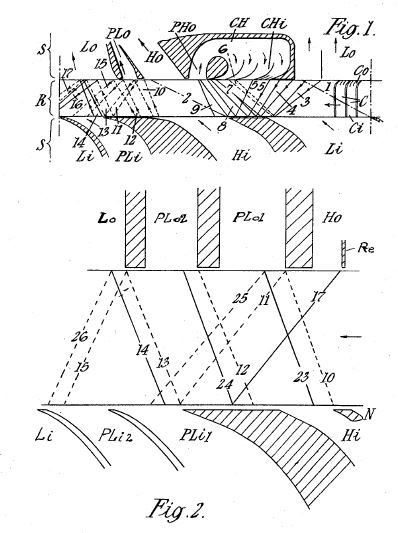
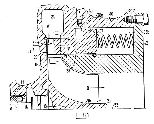
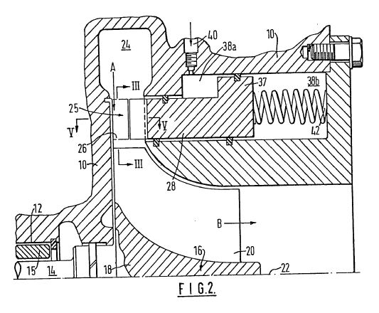
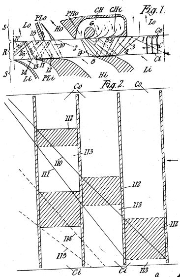
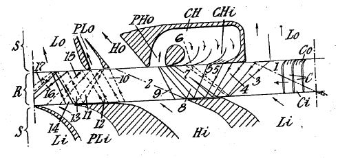
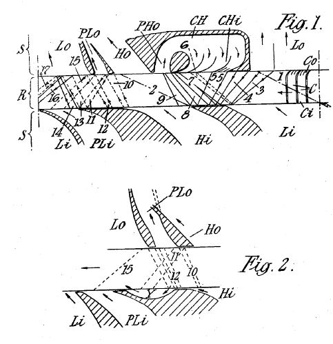
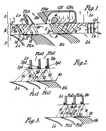
To show how the GWT works a simplified wave-space-time diagram is shown next. It is a development on the mean rotor diameter. The inlet stator is on the left showing the three atmospheric air inlet ports LA (bottom) and opposite these are two exhaust ports LO. Hot gas at 4.5 atmospheres pressure enters at the inlet stator port HGi and compressed air is delivered from the opposite port on the right HAo. This air passes through a combustion chamber to be returned to HGi. Other ports and ducts are provided that allow the rotor to produce shaft power in the manner of a turbine and also permit a wide operating speed range to be achieved without using any adjustable port edges. The main compression waves are the inclined solid lines. Expansion waves are in dashed lines and contact surfaces between hot gas and cooler air are in chain dotted lines. The rotor cell, shown at the top, is idealised to match the wave diagram. Waves relate to the leading wall. Each wave is represented by two lines. The first is the ‘wave foot’ where it starts and the second is the ‘wave head’.

Where the American teams failed mostly was in not taking account of the width of rotor cells and not cancelling waves carried over from one cycle to the next. Also their designs meant that operation was confined to a very narrow speed range.
In the design shown these requirements were met by providing the driving nozzles that produced shaft power from the energy needed to eliminate carry-over waves. The duct PAo tapped compressed air delivered by partial opening of the cell outlets as they transferred to the high pressure duct HAo leading to the combustor. This arrangement was one feature that allowed a wide speed range to be achieved. Another was the low pressure hot gas inlet nozzle MGi fed from the gas outlet duct MGo. Note the finite width of walls separating ducts at different pressures. These widths, a fraction of the cell pitch, have to be carefully chosen.
The next stage, if development had continued, would have used the GWT to drive a centrifugal compressor of 3:1 pressure ratio so that with the 5:1 of the GWT an overall pressure ratio of 15:1 would have been provided. This promised good fuel economy. The power output would have been provided by a single stage gas turbine connecting with the GWT outlet duct.
Advantages of such a combination are instant response to throttle and a better part load performance than straight gas turbines. They also promise to be much cheaper since gas turbines for high pressure ratio need very large numbers of very small blades.
References
1. Penrose, R.: http://discovermagazine.com/2009/sep/06-discover-interview-roger-penrose-says-physics-is-wrong-string-theory-quantum-mechanics
2. Smolin, Lee: The Trouble with Physics; Allen Lane Penguin (2007).
3. Pearson, R.D.: PRESSURE EXCHANGERS AND PRESSURE EXCHANGE ENGINES. pp.903-936; The Thermodynamics and Gas Dynamics of Internal Combustion Engines Volume II. Edited by J.H. Horlock and D.E. Winterbone: Clarendon Press: Oxford: 1986.
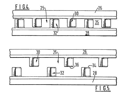
PATENTS
CA975643
Pulse Combustion Installations
[ PDF ]
EP0034915
Improvements in Radially Inward Flow Turbines
[ PDF ]
US2904242
Pressure Exchangers
[ PDF ]
US2904243
Pressure Exchangers
[ PDF ]
US2904244
Pressure Exchangers
[ PDF ]
US2904245
Pressure Exchangers
[ PDF ]
US2904246
Pressure Exchangers
[ PDF ]
Pulse Combustion Installations
[ PDF ]
EP0034915
Improvements in Radially Inward Flow Turbines
[ PDF ]
US2904242
Pressure Exchangers
[ PDF ]
US2904243
Pressure Exchangers
[ PDF ]
US2904244
Pressure Exchangers
[ PDF ]
US2904245
Pressure Exchangers
[ PDF ]
US2904246
Pressure Exchangers
[ PDF ]