Dental Electro-Mineralization
http://www.mirror.co.uk/news/uk-news/no-more-fillings-invention-allows-3701874
Jun 16, 2014
by Andrew Gregory
Electrically Accelerated and Enhanced Remineralisation could spell the end of the dreaded filling as it prepares damaged enamel and then uses a tiny electric current to push calcium and minerals into the tooth
The dreaded dentist’s drill could soon be a thing of the past thanks to a painless new tooth treatment.
Scientists will today unveil the device which allows decayed teeth to rebuild themselves without fillings and could be available in three years’ time.
Professor Nigel Pitts, one of its creators, said: “The way we treat teeth today is not ideal. When we repair a tooth by putting in a filling, it enters a cycle of drilling and re-filling as ultimately each repair fails.
“Not only is our device kinder to the patient and better for their teeth but it’s expected to be at least as cost-effective as current dental treatments.” Prof Pitts, of King’s College London, said the device also whitened teeth.
The treatment, named Electrically Accelerated and Enhanced Remineralisation, prepares damaged enamel and then uses a tiny electric current to push calcium and minerals into the tooth.
A firm called Reminova has been set up in Perth, Scotland, to introduce the treatment. It is the first company to emerge from King’s Dental Innovation and Translation Centre, which aims to bring such technology to market.
King’s College is also part of MedCity, a project to make universities in the South East world leaders in life sciences. MedCity chairman Kit Malthouse said: “It’s brilliant to see the really creative research taking place at King’s making its way out of the lab so quickly”.
http://www.kcl.ac.uk/newsevents/news/newsrecords/2014/June/Kings-spin-out-will-put-tooth-decay-in-a-time-warp.aspx
Dentists could soon be giving your teeth a mild ‘time warp’ to encourage them to self-repair, thanks to a new device being developed by dental researchers. Reminova Ltd, a new spin-out company from King’s College London, aims to take the pain out of tooth decay treatment by electrically reversing the process to help teeth ‘remineralise’.
With 2.3 billion sufferers annually, dental caries is one of the most common preventable diseases globally. Tooth decay normally develops in several stages, starting as a microscopic defect where minerals leach out of tooth. Minerals continue to move in and out of the tooth in a natural cycle, but when too much mineral is lost, the enamel is undermined and the tooth is said to have developed a caries lesion (which can later become a physical cavity). Dentists normally treat established caries in a tooth by drilling to remove the decay and filling the tooth with a material such as amalgam or composite resin.
Reminova Ltd takes a different approach – one that re-builds the tooth and heals it without the need for drills, needles or amalgam. By accelerating the natural process by which calcium and phosphate minerals re-enter the tooth to repair a defect, the device boosts the tooth’s natural repair process. Dentistry has been trying to harness this process for the last few decades, but the King’s breakthrough means the method could soon be in use at the dentist’s chair.
The two-step method developed by Reminova first prepares the damaged part of the enamel outer layer of the tooth, then uses a tiny electric current to ‘push’ minerals into the tooth to repair the damaged site. The defect is remineralised in a painless process that requires no drills, no injections and no filling materials. Electric currents are already used by dentists to check the pulp or nerve of a tooth; the new device uses a far smaller current than that currently used on patients and which cannot be felt by the patient.
The technique, known as Electrically Accelerated and Enhanced Remineralisation (EAER), could be brought to market within three years.
The company is the first spin-out from the King’s College London Dental Innovation and Translation Centre which was launched in January 2013. This centre was formed to take research and novel technologies and turn them into products, change practice and inform policy which will improve health and healthcare internationally.
Reminova Ltd will be based in Perth, Scotland to benefit from the strong life sciences and dentistry base. It will commercialise the work of Professor Nigel Pitts and Dr Chris Longbottom, based in the Dental Institute at King’s College London. With a combined 80 years’ experience in dentistry they have previously brought dental devices to market to detect tooth decay. The company was formed in collaboration with Innova Partnerships, who commercialise healthcare and life science enterprises.
The company is currently seeking private investment to develop their remineralisation device.
Professor Nigel Pitts from the Dental Institute at King’s College London said: “The way we treat teeth today is not ideal – when we repair a tooth by putting in a filling, that tooth enters a cycle of drilling and re-filling as, ultimately, each “repair” fails.
“Not only is our device kinder to the patient and better for their teeth, but it’s expected to be at least as cost-effective as current dental treatments. Along with fighting tooth decay, our device can also be used to whiten teeth.” ...
http://www.reminova.com/
INNOVATIVE SOLUTIONS FOR CARIES PREVENTION, TREATMENT AND MANAGEMENT.
NEWS
Monday 16 June 2014
Dentists could soon be giving your teeth a mild ‘time warp’ to encourage them to self-repair, thanks to a new device being developed by dental researchers. Reminova Ltd, a new spin-out company from King’s College London, aims to take the pain out of tooth decay treatment by electrically reversing the process to help teeth ‘remineralise’.
The company is the first spin-out from the King’s College London Dental Innovation and Translation Centre which was launched in January 2013. This centre was formed to take research and novel technologies and turn them into products, change practice and inform policy which will improve health and healthcare internationally.
Reminova Ltd will be based in Perth, Scotland to benefit from the strong life sciences and dentistry base. It will commercialise the work of Professor Nigel Pitts and Dr Chris Longbottom, based in the Dental Institute at King’s College London. With a combined 80 years’ experience in dentistry they have previously brought dental devices to market to detect tooth decay. The company was formed in collaboration with Innova Partnerships, who commercialise healthcare and life science enterprises.
The company is currently seeking private investment to develop their remineralisation device. For a full press release and to find out more about the technology, visit
IMPROVED APPARATUS AND METHOD FOR MINERALISING BIOLOGICAL MATERIAL
Abstract -- According to the present invention, there is provided an apparatus for mineralising a biological material, the apparatus comprising an ultrasonic source, operable to generate an ultrasonic signal, an ultrasonic probe and one or more mineralising probes, operable to receive a mineralising agent, wherein the mineralising agent is transferred from at least one mineralising probe to the biological material using the ultrasonic signal. There is also provided a mineralisation agent and a method of mineralising a biological material, said method comprising the steps of: providing an ultrasound source, providing a mineralising agent, generating an ultrasonic signal from the ultrasound source, applying the ultrasonic signal and the mineralising agent to the biological material separately, sequentially or simultaneously.
The present invention relates to an apparatus and method for mineralising biological material and in particular for re-mineralising demineralised and hypo-mineralised tissue, such as tooth or bone.
Caries is the decay of tooth or bone. Dental caries (also known as dental decay, caries or carious lesions) is caused by acids produced by microbial enzymatic action on ingested carbohydrate. The acids decalcify (demineralise) the inorganic portion of the tooth initially creating a sub-surface lesion, the organic portion then disintegrates leading to the creation of a cavity. In dentistry, demineralisation of a tooth through the development of a carious lesion can be described in terms of the depth of the carious lesion.
Dental caries is commonly treated by the removal of the decayed material in the tooth and the filling of the resultant hole (cavity) with a dental amalgam or other restorative material. In more severe cases, the entire tooth may be removed. Prior to lesion cavitation, it is possible to heal or reverse the tissue destruction by remineralising the caries lesions. However, this process works better where exogenous (e.g. salivary- or food-derived) proteins and lipids have been removed from the caries lesions.
It is known that the level of tooth decay alters the electrical characteristics of a tooth. This arises because as minerals are lost the porosity of the tooth increases and the consequent increased numbers of ions within the pores increase the conductivity i.e. the electrical transport in the tooth. Consequently, demineralisation of a tooth will result in an
enhancement of its charge transport properties. This may be manifested in a decrease in the potential difference which must be applied to a demineralised tooth, compared with a healthy tooth, in order to achieve a comparable current therethrough. Correspondingly, this may be manifested in an increased current measurable from a demineralised tooth, compared with a healthy tooth, on application of the same potential difference. These effects can be detected on application of a constant current or constant potential difference respectively.
Alternatively, the impedance (which includes the DC resistance) can be monitored by using AC signals.
There are a number of devices specifically designed to detect dental caries by the application of an alternating electrical current to a tooth using a probe or contact electrode and counter electrode. As described above, the main source of impedance in the circuit formed by the counter electrode and the probe is provided by the tooth and therefore changes to the impedance of the circuit give a measure of changes in the impedance of the tooth. This technique is described in international patent application WO97/42909.
Iontophoresis is a non-invasive method of propelling a charged substance, normally a medication or a bioactive agent, using an electric current. It is known to use iontophoresis in transdermal drug delivery. Iontophoresis may also be used in conjunction with fluoride containing compounds to treat dentine hypersensitivity and to remineralise non-cavitated dental caries lesions. Iontophoresis devices typically include an active electrode assembly and a counter electrode assembly each coupled to opposite poles or terminals of a voltage source. The active agent can be cationic or anionic and the voltage source can be configured to apply the appropriate voltage polarity based upon the polarity of the active agent. The active agent may be stored in for example, a reservoir such as a cavity or in a porous structure or a gel. Ultrasound is a longitudinal pulse..It is known to use ultrasound for trans-dermal drug delivery -sonophoresis. In dentistry ultrasound is known generally for cleaning, e.g. removal of calculus from the external surface of teeth or debris from the pulp chamber and root canal inside a tooth during root canal treatment. Electrosonophoresis is a combination of iontophoresis and ultrasound.
It is an object of the present invention to provide an improved apparatus, system and method for mineralising biological material. In accordance with a first aspect of the invention there is provided apparatus for mineralising a biological material, the apparatus comprising an ultrasonic source, operable to generate an ultrasonic signal, an ultrasonic probe and one or more mineralising probes, operable to receive a mineralising agent, wherein the mineralising agent is transferred from at least one mineralising probe to the biological material using the ultrasonic signal.
At least one mineralising probe may be the ultrasonic probe.
According to one embodiment, the apparatus comprises an iontophoresis probe.
The apparatus of the present invention may utilise electrosonophoresis. The apparatus advantageously further comprises a first electrode and a second electrode and an electrical signal generator, operable to generate an electrical signal between the first and second electrodes, a detector, operable to detect the electrical response of the electrical signal between the first and second electrodes, and a controller operable to receive the detected electrical response and to control the ultrasonic signal relative thereto.
The apparatus advantageously further comprises a mineralising probe electrode and a modulator, operable to modulate the electrical signal between the mineralising probe electrode and the second electrode and thereby cause the transfer of mineralising agent to the biological material using the electrical signal.
Advantageously, the mineralising probe electrode is the first electrode.
The controller is preferably operable to control modulation of the electrical signal relative to the detected electrical response.
The apparatus advantageously further comprises a reference electrode operable to control at least one of the modulation of the electrical signal and the ultrasonic signal.
The controller advantageously comprises a first software module having a dataset which describes the characteristic electrical response of a sample biological material at various stages of mineralisation, and a second software module which compares said data with the detected electrical response and thereby determine any required modification of at least one of the electrical signal and ultrasonic signal.
The second software module may apply a function which defines the relationship between mineralisation and the electrical response in order to compare said data with the detected electrical response and to thereby determine any required modification of at least one of the electrical signal and ultrasonic signal.
Alternatively, the second software module may apply a look-up table containing information on the electrical response of the biological material and its mineralisation in order to compare said data with the detected electrical response and to determine any required modification of at least one of the electrical signal and ultrasonic signal.
The mineralising probe electrode advantageously transfers the mineralising agent to the biological material by iontophoresis. According to one embodiment, the mineralising probe electrode advantageously transfers the mineralising agent to the biological material by electrosonophoresis.
When used in accordance with the present invention, ultrasound is generally used in the range of between about 20Hz to 200 MHz; typically from about 5 MHz to about 200MHz; suitably from about 10 MHz to about 150 MHz; more suitably from about 100 MHz to about 150 MHz.
There is an inverse relationship between the ultrasound frequency and the particle size which may be applied to the biological material by the apparatus and method of the present invention. The higher the frequency of the ultrasound, the smaller the particle size which may be applied to the biological material by the apparatus and method of the present invention. Using a higher frequency of ultrasound allows a greater range of particle sizes to be utilised.
The detector is advantageously operable to determine, from the electrical response, the presence of at least one of exogenous proteins and lipids on or in the biological material.
The apparatus may further comprise means for applying a conditioning agent.
The conditioning agent may comprise at least one of an oxidising agent, de-proteinising agent and a de-lipidising agent. Generally the conditioning agent comprises more than one of an oxidising agent, de-proteinising agent and a de-lipidising agent, typically the conditioning agent comprises at least a de-proteinising agent and a de-lipidising agent.
The apparatus is advantageously operable to apply the ultrasonic signal and transfer the mineralising agent separately, sequentially or simultaneously.
The apparatus is advantageously operable to apply the ultrasonic signal and the electrical signal separately, sequentially or simultaneously.
The apparatus is advantageously operable to apply the modulated electrical signal and transfer the mineralising agent separately, sequentially or simultaneously. According to one embodiment, the apparatus is operable to apply the ultrasonic signal and an iontophoresis signal separately, simultaneously or sequentially and/or in combination. Generally the ultrasonic signal and the iontophoresis signal are applied simultaneously. The apparatus is advantageously adapted for use with hard tissue biological materials such as tooth and/or bone.
Advantageously, the operation of the apparatus of the present invention can be interrupted in order to re-apply the conditioning agent thereby removing exogenous proteins and/or lipids.
In accordance with a second aspect of the present invention there is provided a mineralising agent for use with apparatus, as described above, for mineralising biological material.
The mineralising agent may comprise at least one of a source of calcium ions and a source of phosphate ions and source of hydroxyl ions (such as water), optionally in the presence of a source of fluoride ions.
Generally the mineralising agent comprises a source of calcium ions and a source of phosphate ions and a source of hydroxyl ions (such as water). Typically the mineralising agent comprises a source of calcium ions, a source of phosphate ions, water, and a source of fluoride ions.
The mineralising agent may be in a form soluble in water or insoluble in water (in an aqueous dispersion) under the conditions generally used to operate the apparatus/conduct the method of the present invention.
The mineralising agent may comprise casein phosphopeptide - amorphous calcium phosphate (CPP-ACP) The mineralising agent may comprise calcium, phosphate, hydroxy l/water and fluoride.
The mineralising agent may comprise casein phosphopeptide - amorphous calcium fluoride phosphate (CPP-ACFP). The mineralising agent suitably comprises one or more mineralisation enhancers. More suitably, the mineralising agent comprises two mineralisation enhancers, wherein one of the enhancers is a source of calcium ions and the other is a source of phosphate ions.
The mineralising agent preferably comprises a calcium:phosphate ratio of between 1 :1 and 22:10. More preferably, the mineralising agent comprise a calcium:phosphate ratio of between 3:2 and 22:10. More preferably, the mineralisation agent comprises a
calcium:phosphate ratio of approximately 10:6. Alternatively or additionally, at least one of the mineralisation enhancers may comprise strontium.
The mineralisation agent advantageously comprises nano-particles, having an average particle diameter of less than 500nm, generally less than 100nm, typically less than 50nm, suitably less than 10nm, more suitably from 1 to 10nm. According to one embodiment, the mineralisation agent consists of nano-particles.
According to one embodiment, the average particle diameter of the mineralisation agent is 1 to 50nm.
The use of a mineralisation agent comprising or consisting of nano-particles is believed to allow a greater proportion of the mineralisation agent to be forced into the biological tissue, promoting a more efficient mineralising method, and/or greater retention of the mineralisation agent in the biological tissue.
The nano-particles typically comprise at least one of a source of calcium ions, a source of phosphate ions, a source of hydroxyl ions and a source of fluoride ions. Generally the nano- particles comprise calcium hydroxyapatite.
According to a third aspect of the present invention there is provided a kit comprising apparatus for mineralising a biological material, as described above, and a mineralisation agent as described above. The kit may further comprise a conditioning agent.
According to a fourth aspect of the present invention there is provided a method of mineralising a biological material, comprising the steps of: providing an ultrasound source, providing a mineralising agent, generating an ultrasonic signal from the ultrasound source, applying the ultrasonic signal and the mineralising agent to the biological material separately, sequentially or simultaneously.
The method of the present invention generally involves the use of the apparatus as described herein.
According to one embodiment, the method may be involve electrosonophoresis.
Whilst the inventors do not wish to be bound by theory, it is believed that the use of electrosonophoresis (the combination of ultrasound and iontophoresis), in a method of mineralising biological material allows a greater proportion of the mineralising agent to be forced into the biological material, rather than remaining on the surface of the biological material. This allows a more effective method of mineralisation. More mineralising agent is forced into the biological material in a shorter time period than equivalent methods using only iontophoresis. The use of electrosonophoresis is also believed to promote greater retention of the mineralising agent in the biological material, meaning that the mineralisation of the biological tissue lasts for longer than methods using only iontophoresis,
The method may further comprise the step of conditioning the biological material prior to applying at least one of the ultrasonic signal and mineralising agent thereto. The step of conditioning comprises at least substantially removing at least one of protein and lipids from the biological material (generally substantially removing both of proteins and lipids from the biological material). The step of conditioning preferably comprises the application of at least one of a deproteinisation agent and a delipidisation agent.
The method advantageously further comprises the steps of: providing a first electrode and a second electrode, an electrical signal generator and a controller; generating an electrical signal between the first and second electrodes; detecting the electrical response of the electrical signal, between the first and second electrodes; and controlling the ultrasonic signal relative to the detected electrical response.
The method advantageously further comprises the steps of providing a mineralising probe; providing a modulator; modulating the electrical signal between the mineralising probe and the second electrode and thereby cause the transfer of mineralising agent to the biological material using the electrical signal.
The mineralising probe may be provided by the first electrode.
The method advantageously further comprises the step of controlling the modulation of the electrical signal relative to the detected electrical response.
The method advantageously further comprises the step of providing a reference electrode and controlling at least one of the modulation of the electrical signal and the ultrasonic from information derivable therefrom.
The steps of controlling at least one of the ultrasonic signal and the electrical signal relative to the detected electrical response may comprise the steps of: comparing a dataset of characteristic electrical responses derived from a set of samples of biological material at various stages of mineralisation with the detected electrical response; and determining any required modification to at least one of the ultrasonic signal or electrical signal. The step of comparing the data set may comprise applying a function which defines the relationship between the mineralisation and the electrical response in order to compare said data with the detected electrical response.
Alternatively, the step of comparing the data set may comprise applying a look-up table containing information relating to the electrical response of the biological material and its mineralisation; and comparing the said data with the detected electrical response.
The method may further comprise the step of detecting the presence of at least one of proteins (such as exongenous proteins) and lipids on or in the biological material from the detected electrical response; typically detecting the presence of proteins and lipids.
The mineralising agent is generally as described above.
The mineralising agent may comprise casein phosphopeptide - amorphous calcium phosphate (CPP-ACP)
The mineralising agent may comprise calcium, phosphate, hydroxyl/water and fluoride.
The mineralising agent may comprise casein phosphopeptide - amorphous calcium fluoride phosphate (CPP-ACFP).
The mineralising agent may be substantially insoluble in water under the conditions used in the method of the present invention. According to one embodiment of the present invention, the mineralising agent remains in or on the bone/dental tissue to which is it applied for at least 3 months, generally at least six months, typically at least one year from application thereto.
The mineralising agent advantageously comprises one or more mineralisation enhancers. More advantageously, the mineralising agent comprises two mineralisation enhancers, wherein one of the enhancers is a source of calcium ions and the other is a source of phosphate ions. The mineralising agent may comprise a calcium:phosphate ratio of between 1 :1 and 22:10.
Preferably, the mineralising agent comprises a calcium:phosphate ratio of between 3:2 and 22:10. More preferably, the mineralisation agent comprises a calcium: phosphate ratio of approximately 10:6.
Alternatively or additionally, at least one of the enhancers may comprise strontium. The mineralisation agent advantageously comprises nano-particles. The nano-particles preferably comprise at least one of calcium, phosphate, hydroxyl and fluoride.
The nano-particles may comprise calcium hydroxyapatite. The method is advantageously adapted for use in mineralising hard tissue such as tooth and/or bone.
The invention will now be described by way of example only with reference to the accompanying drawings in which:
Figures la and lb are graphs which show the applied voltage and the current decay rate for a healthy and a demineralised tooth;
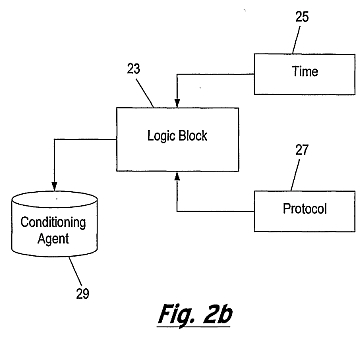
Figure 2a is a flow diagram which shows an embodiment of the method of the present invention and figure 2b is a block diagram of an apparatus for implementing the method of figure 2a;
Figures 3a and 3b are schematic representations of embodiments of the present invention utilising ultrasound only (Figure 3a) and combined ultrasound and iontophoresis (Figure 3b);
Figure 4 is a more detailed schematic representation of the controller of the embodiment of Figure 1 ; Figures 5a and 5b are more detailed schematic representations of the ultrasonic probe and the iontophoresis probe, resepectively, of the embodiments of figures 3a and 3b;
Figure 6 is a flow diagram showing a first embodiment of the method of the present invention; and
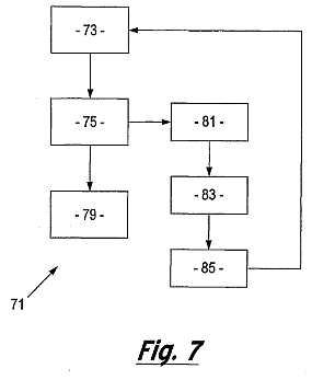
Figure 7 is a flow diagram showing another embodiment of the method of the invention.


The present invention provides an apparatus and method for mineralising a biological material. The invention is particularly suitable for remineralisation of teeth where decay by demineralisation has occurred or for occluding dental tubules to treat dentine hypersensitivity, or for tooth whitening or in the treatment of dental erosion. It will be appreciated that the apparatus and method described herein is not restricted to the remineralisation of teeth but can be used to mineralise other biological material but is particularly applicable to the mineralisation of hard tissue such as, for example, it may be used in the remineralisation of bones for the treatment of osteoporosis, osteopenia or periodontal disease.
Generally the apparatus and method of the present invention involve electrosonophoresis.
In preferred embodiments of the present invention, spatial imaging data or 3D structural information can be used to generate different characterising parameters, including, tracking changes (and/or relative changes) in grey- scale values (in micro-CT images) in a variety of different parallel vectors in any one of many different planes, to generate an average representation of the mineral density changes in the direction of those vectors. The averaging process is performed preferably over the whole volume of the lesion; and the resulting information therefrom is processed to calculate, amongst other parameters, the depth of the carious lesion in the direction of the pulp. In view of the complex spatial geometries of lesions, the image analysis technique provides substantially more information than that normally available to a dentist. Thus, it may be possible to determine other lesion parameters which may be more useful in characterising the loss of mineral density than the traditionally-used lesion depth parameter.
As described previously, changes in the impedance and/or resistance of a tooth can be detected on the application of an AC signal or a DC constant current or constant potential difference. The application of a pulse or square- wave current or potential difference to a healthy or demineralised tooth also yields dynamic information from the plot of current (or potential) vs time.
Figure la is a graph 1 of voltage against time which shows a pulsed voltage 3 of substantially constant magnitude. Figure lb is a graph of current against time which shows the current decay rate in response to the applied potential difference (voltage) pulse for a healthy tooth and one which has been demineralised. The curve 7 shows the current response for the healthy tooth and the curve 9 shows the response for the demineralised tooth.
Using a mechanistic understanding of charge transport through a tooth and the effect of tooth demineralisation on tooth ionic conductivity, a relation may be formed between the mineral density profiles determined from the above-mentioned image processing technique and a measured temporal electrical response profile. The present invention forms the relation through image-analysis and electrical properties analysis of a large number of healthy teeth and teeth with carious lesions by establishing an analytical model which creates a mathematical function to describe this relationship.
Alternatively, the present invention may employ a look-up table between the measured electrical response data and average mineral density values (determined from the above image analysis techniques) obtained from the studies of the healthy and diseased teeth In establishing the above relation and/or look-up table, micro-CT techniques can be used in which data is calibrated against a plurality of phantoms, so as to ensure that the measured variation in grey scale values is actually representative of a change in mineral density though a tooth, as opposed to an aberrant effect (or imaging artefacts). The above process will be described in more detail below.
The apparatus of the present invention employs a feedback mechanism, wherein an electrical measurement (which may be AC or DC related) is made whilst a tooth is being remineralised by iontophoresis. The electrical measurement is related to the mineral density of a carious lesion in the tooth (through the above-mentioned relation and/or look-up table formed during an offline process) to calculate an appropriate control signal for the apparatus to optimally tune the iontophoretic process.
Figure 2a shows an embodiment of the method of the present invention which comprises the following steps. Step 0:
A pre-step which involves calibrating the grey-scale values obtained from a micro-CT analysis (used in forming the mineral density values employed in the above- mentioned relation and/or look-up table) a plurality of phantoms (comprising a homogeneous isotropic material which substantially matches dental material) are scanned using a micro-CT device. In the present example, the phantoms comprise hydroxyapatite disks representing a particular material density.
Step I:
Following the micro-CT analysis of the phantoms alone, a plurality of healthy teeth and teeth with carious lesions are each subjected to a similar scanning process, together with the phantoms. The calculated mineral densities of the scanned teeth are processed using a known segmentation technique to identify the boundaries of any lesions therein. A profile of the mineral density is established within the boundaries determined by the segmentation process; and the mineral density profiles are related to a steady-state or temporal electrical measurement obtained from the same teeth.
Step 2:
During the application of an ultrasonic signal and generally, iontophoresis, a constant potential difference or current is applied to a tooth with a carious lesion 13. An electrical response function is measured 15 from the tooth under treatment; and the relation (and/or look-up table) established in Step 1 is used to determine 17 the mineral density of the carious lesion.
Step 3:
The mineral density range of the healthy tooth material proximal to the boundaries established during step 1 is determined 19. This is used to establish the desired degree of remineralisation required of the ultrasonic signal (and generally iontophoretic) treatment. Step 4:
A change in the magnitude of the ultrasonic (and generally iontophoretic) signal is calculated 21 , the calculated change being sufficient to drive mineral into the lesion so that the mineral density of the lesion more closely matches that of the healthy dental material.
In implementing the method of Figure 2a, the apparatus of Figure 2b comprises a logic block 23, which in addition to receiving an indication of the desired change in the magnitude of the ultrasonic (and generally iontophoretic) signal (from Step 4), receives information regarding the time 25 over which the iontophoresis treatment has been operating. The logic block 23 also receives additional protocol information 27 regarding times for example at which the ultrasonic (and generally iontophoresis) should be started or stopped (e.g. to allow the electrical probe to be cleaned and further conditioning agent 29 to be applied thereto). The apparatus according to the present invention may function to mineralise biological material either using ultrasound alone to propel mineralising agent into the biological material or a combination of ultrasound and iontophoresis. Figure 3a shows a first embodiment of an apparatus 31 for mineralising a biological material, in accordance with the present invention, comprising an ultrasonic probe 33 having a handle 35, a neck 37 and head 39. The ultrasonic probe 33 is connected to an ultrasound source 40 and a controller 41 , by cable 45, which in turn is connected to a second counter electrode 43 by cable 47. Electrode 43 may be a hand-held or mouth or lip "loop" electrode.
Figure 3b shows a second embodiment of an apparatus 131 for mineralising a biological material, in accordance with the present invention, comprising an ultrasonic probe 133a having a handle 135a, a neck 137a and head 139a. The apparatus further comprises an iontophoresis probe 133b, operable as a fist electrode, having a handle 135b, a neck 137b and a head 139b. The ultrasonic probe 133a is connected to an ultrasound source 140 and a controller 141 , by cable 145, which in turn is connected to a second counter electrode 143 by cable 147. Electrode 143 may be a hand-held or mouth or [Iota][iota][rho]'[Iota][omicron][omicron][rho]" electrode. The iontophoresis probe 133b is also electrically connected to the controller 141.
Figure 4 shows, in more detail, the controller 41 which comprises a modulator 49 which adjusts the ultrasonic signal to the ultrasonic probe 33a (133a) and, if the iontophoresis probe 133b in accordance with the second embodiment is utilised, modulates the shape and/or frequency and/or amplitude of the waveform sent to the probe 133b.
Figure 5a shows the ultrasonic probe 33 (133a), in more detail, wherein it has an ultrasonic waveguide 34 which extends through the handle 34 of the probe to the ultrasound source 40. Disposed between the head 39 (139a) and the ultrasound source 40 is a reservoir 55 (155a) for storing mineralising agent 57 (157a). In use, the mineralisation agent is propelled out from the reservoir 55 (155a) through the head 39 (139a) of the probe 33 (133a) by the ultrasonic signal and into contact with the biological material such as, for example, a tooth or bone.
Figure 5b shows the iontophoresis probe 133b, in more detail, wherein the cable 45 extends through the handle 135b of the probe 133b to a reservoir 155b containing a mineralising agent 157b. In use, the mineralisation agent is propelled out from the reservoir 155b, by the electrical signal (iontophoresis) through the head 139b of the probe 133b and in to contact with the biological material such as, for example, a tooth or bone. In other embodiments of the present invention, the mineralising agent may be stored in other ways such as in a porous structure or a gel which may be applied directly to a tooth. In
embodiments of the present invention where the mineralising agent is stored in a chamber in the probe it can be introduced onto the probe surface by making the chamber of flexible material to allow the mineralising agent to be squeezed out. Alternatively, the chamber may have a plunger or similar component which pushes the mineralising agent out of the chamber.
In order to prevent cross-infection the mineralising agent is typically held separately from the device or embodied as a detachable 'probe tip' which detachably attachable to the end of the probe.
Figure 6 is a flow chart 61 which shows a method of the present invention in which the ultrasonic signal and (if iontophoresis is used) the waveform of the electrical signal in the circuit formed from the first (probe) electrode 33(133a and/or 133b) and the second counter electrode 43 (143) is controlled so as to transfer a mineralising agent to the biological material 63. The electrical response of the circuit is then detected 65 and the detected signal is analysed so as to determine whether or not the signal needs to be modified and, if so to what extent, in response to the detected electrical response of the circuit 67.
The following example of use of an embodiment of the present invention is given in relation to the remineralisation of teeth. The dentist identifies, within a patient, a specific tooth site which is to be remineralised. Thereafter a conditioning agent is applied and the site is cleansed to remove exogenous proteins and/or lipids from the site. The conditioning agent may be propelled into a hypo-mineralised or demineralised caries lesion, by iontophoresis, utilising the probe and counter electrodes, to optimise the disruption and removal of the exogenous protein and/or lipid content.
The probe 33 (133a/133b) is inserted into the mouth of the patient and on to the tooth site. The counter electrode 43 (143) is connected to the patient. The probe(s), which in this example comprises an ultrasonic (and optionally an iontophoretic) device, propels the mineralising agent 57 (157) through the external surface of the tooth in order to remineralise the caries lesion at that tooth site.
During this process, the electrical circuit formed by the probe(s) 33 (133a/133b), patient and counter electrode 43 (143) provides an output signal which identifies changes in the electrical response of the circuit which have been caused by the ongoing remineralisation process. The electrical response is detected by detector 53, the signal is passed to the controller 51 which processes and compares the electrical response to a dataset of known, experimentally obtained electrical responses to remineralisation. These responses provide 3D structural information on the amount and location of remineralisation of the tooth. The controller is therefore able to send program instructions to the modulator to alter the ultrasonic signal and waveform of the electrical signal input to the probe(s) 33 (133a/133b) by changing its frequency and/or amplitude and/or shape. Once any change to the ultrasonic signal and waveform has been determined, the modulator 49 provides an output to the probe(s) 33 (133a/133b) which in turn determines the manner in which the mineralising agent is propelled through the external surface of the tooth. A response to changes in the remineralisation pattern of the tooth can be made in real time or otherwise.
The comparison of the dataset of known, experimentally obtained electrical responses to remineralisation with the output signal detected by detector 53 requires the creation of a dataset or library of experimentally obtained responses. This information is derived from experimental data in which micro CT images are taken to provide virtual tooth slices. In this example of the present invention, the process is as follows.
A sample having dental caries, or other general defects (e.g. loss of mineral density), is scanned using a 3D tomography system (e.g. x-ray, MRI, neutron (ultrasound). A calibration phantom is used to determine the relationship between attenuation coefficient and electron density; hardware and software solutions are used to minimise intrinsic image artefacts (e.g. beam hardening, ring artefacts, scattering). Reconstruction of the sample is achieved using acquired 2D angular projection images, and is accomplished for different voxel (i.e. 3D pixels) or spatial resolutions. 3D image processing algorithms are employed to calculate spatial distributions of electron density, as represented by attenuation data linked to the phantom. These distributions provide information on the degree of mineralization of relevant volumes of interest.
After ultrasonic (and generally iontophoretic) remineralisation treatment, the sample is rescanned and subjected to the above mentioned methodologies. The subsequent distributions (before and after treatments) of mineral density of relevant volumes of interest are compared to inform of induced changes in mineralization patterns.
This process is repeated for samples with varying degrees of remineralisation to provide information on changes in internal sample structure, which can be related to changes in electrical responses of the sample which occurred during the treatment of the sample.
The described technique would inform any spatial heterogeneity of remineralisation, providing feedback from the electrical responses of the sample to the spatial location of remineralisation. Representative experimentally acquired datasets are encoded into the device library to provide characteristic signatures of the spatial location and distribution of mineral densities which enable the clinician to decide on real-time responses to remineralisation patterns. The feedback provided by the integration of the AC impedance or DC resistance values from the sample tooth and its incorporation in the controller, informs the settings of the device in order to optimise the remineralisation of the tissue. Suitably, the initial settings may involve the use of controlled potential coulometry where longer pulses are applied or chrono-amperometry where shorter pulses are applied. Feedback on the nature and extent of the remineralisation process provided by the present invention includes information about if and when to switch the settings to controlled current coulometry to optimise the remineralisation throughout the lesion.
In the case of controlled current coulometry the current is at a constant level which means that the flow of the remineralising agent would be constant also. This would be desirable in promoting a constant rate of remineralisation, since the rate of remineralisation is expected to be directly proportional to the amount of current flowing. Alternatively, the current may be allowed to fall as a function of time and so the rate of remineralisation is not constant with time.
In the embodiment of the present invention shown in figure 7, in addition to characterising the state of mineralisation of the tooth, the electrical response of the circuit gives information indicative of the build-up of exogenous proteins and/or lipids in the area of interest. The flow diagram 71 illustrates the transfer of a mineralising agent to the biological material 73. The electrical response of the circuit is then detected 75 and the detected signal is analysed so as to determine whether, and the extent to which, the ultrasonic signal and electrical signal needs to be modified in response to the detected electrical response of the circuit 77. In addition, the detector of the present invention is adapted to detect 81 changes in the electrical response that are as a result of a build up of exogenous proteins, lipids and other materials. Once detected the remineralisation process is interrupted 83 and a conditioning agent is re-applied 85 for a specific period. Thereafter, the process of remineralisation may resume.
The presence of the exogenous proteins and/or lipids may be indicated by the apparatus of the present invention by analysis of the electrical response. In these circumstances, the user will be advised that a re-conditioning step is required and will take the appropriate action to re-apply a conditioning agent.
In another embodiment of the invention, the apparatus is provided with a reference electrode which in this example comprises a small Ag/ AgCI wire placed close to the probe electrode. The reference electrode allows more precise control of electrical potential and is of particular use when large currents are required to treat large lesions. The impedance of the tooth can be measured by the application of an AC signal as described above. Alternatively, a current interruption technique can be used whereby a current is applied for a certain amount of time and then the circuit is broken rapidly using a relay. The decay of the potential with time can give information on the resistance of the tooth.
In addition, the invention can be used in the preconditioning of, for example, a tooth where ultrasonic signals (and generally iontophoresis) are used in preconditioning. A conditioning agent may be propelled into a hypo-mineralised or demineralised caries lesion, by ultrasonic signals (and generally iontophoresis) to optimise the disruption of the exogenous protein and lipid content and then the polarity of the iontophoresis reversed, if required, in order to aid the removal of the proteinacious and other organic material from the hypo-mineralised or demineralised tissue. Examples of suitable agents include bleach, detergent, chaotropic agents such as urea, high phosphate concentrations, cocktails of proteases (e.g. endopeptidases, proteinases and exopeptidases) and any other protein solubilising, disrupting or hydrolysing agent. In this example of the present invention, the probe is attached to a detachable chamber containing a conditioning agent and ultrasound (and optionally iontophoresis) is used with this chamber to propel the conditioning agent into the tooth prior to the remineralising step. The apparatus and method of the present invention provides electrical feedback during ultrasonic (and generally iontophoretic) conditioning to a detector and a controller which modifies the waveform of the electrical input in response to the detected electrical response of the circuit during conditioning. According to a third aspect of the present invention a kit comprises apparatus as described above and a mineralising agent. The kit may further comprise a conditioning agent.
The conditioning agent is an oxidising agent, de-proteinising agent or a de-lipidising agent. According to a fourth aspect of the present invention a mineralising agent comprises a source of phosphate, calcium and hydroxy l/water. The remineralising agent may comprise casein phosphopeptide-amorphous calcium phosphate (CPP-ACP). The remineralising agent may comprise nano-particles of (calcium) hydroxyapatite. In a preferred embodiment the remineralising agent contains fluoride. An example of such a remineralising agent is casein phosphopeptide-amorphous calcium fluoride phosphate (CPP-ACFP).
The remineralising agent also advantageously includes one or more remineralisation enhancers. Typically the remineralising enhancers are sources of calcium and phosphate ions. Examples of remineralisation enhancers may include, but are not limited to, Dicalcium phosphate dehydrate (DCPD), mineral brushite; Dicalcium phosphate anhydrous (DCPA), mineral monetite; Octacalcium phosphate (OCP); alpha-tricalcium phosphate (alpha-TCP); beta-tricalcium phosphate (beta-TCP); Amorphous calcium phosphate (ACP); Calcium- deficient hydroxyapatite (CDHA); Hydroxyapatite (HA or OHAp); Fluorapatite (FA or FAp); Tetracalcium phosphate (TTCP or TetCP), mineral hilgenstockite); nano-particles of hydroxyapatite or fluorhydroxyapatite. More preferably, the remineralisation enhancer is strontium. The remineralising agent may include at least two remineralisation enhancers wherein one of the enhancers is a source of calcium ions and the other is a source of phosphate ions. For example the remineralising agent may include a source of calcium e.g. calcium hydroxide and a source of phosphate e.g. orthophosphoric acid. The ratio of calcium:phosphate in the remineralising agent may be between 1 :1 and 22:10. Preferably the ratio of calcium:phosphate is about 10:6 (i.e. 1.67), which represents the ratio of calcium to phosphate ions in calcium hydroxyapatite. Alternatively the ratio of calcium:phosphate in the remineralising agent may be between 9:6 and 22:10. Alternatively still, the ration of calcium:phosphate in the remineralising agent may greater than 1 :1 but less than 3:2 (i.e. 1.0 up to 1.49).
The remineralising agents may thus be selected from the following:
i) Ca:P ratio = 1.67: e.g. Hydroxyapatite (including nano-particles): Fluorapatite.
ii) Ca: P ratio = 1.5 - 2.2 (but not 1.67): e.g. Alpha-Tricalcium phosphate; Beta-Tricalcium phosphate; Amorphous calcium phosphate; Calcium deficient Hydroxyapatite; Tetracalcium phosphate, mineral hilgenstockite.
iii) Ca:P ratio = 1-1.49: e.g. Dicalcium phosphate dehydrate, mineral brushite; Dicalcium phosphate anhydrous, mineral monetite. The remineralising agent may be prepared from its component parts by driving in calcium ions sonophoretically (in aqueous solution) and subsequently driving in phosphate ions (in aqueous solution) with a second sequence of sonophoresis - the calcium and phosphate ions would thus meet within the lesion during the second sequence of sonophoresis and precipitate out as a calcium phosphate mineral (or minerals). The hydroxyl ion of the generated apatite would come from the aqueous solution. The water-soluble calcium- containing agent may be, for example, calcium hydroxide, calcium chloride, or calcium nitrate; the water-soluble phosphate-containing agent may be, for example, orthophosphoric acid (H 3PO 4), sodium (or potassium) hydrogen phosphate, sodium (or potassium) dihydrogen phosphate or magnesium phosphate. The calcium agent containing solution may be separate from the phosphate agent containing solution, or combined into one solution.
Thus a preferred method of the invention may comprise the steps of: i) pre-conditioning the biological material (hard tissue) to remove protein and/lipids, and ii) applying to the hard tissue a calcium phosphate-containing aqueous solution whilst separately, sequentially or simultaneously applying ultrasound. The pre-conditioning step can be effected with or without the use of ultrasound to drive in the de-proteinisation agent, e.g. sodium hypochlorite. The frequency of this ultrasound can be in the range which will generate cavitation or Ultrasonic streaming.
A further preferred method of the invention comprises the steps of i) pre-conditioning the biological material (hard tissue) to remove protein and/lipids ii) applying to the tissue a calcium-containing aqueous solution or phosphate-containing aqueous solution whilst separately, sequentially or simultaneously applying sonophoresis, and iii) either (a) applying a phosphate-containing aqueous solution where in (ii) a calcium-containing aqueous solution was applied or (b) applying a calcium-containing aqueous solution where in (ii) a phosphate- containing aqueous solution was applied whilst separately, sequentially or simultaneously applying sonophoresis. The pre-conditioning step is performed, with or without the application of ultrasound, prior to application of the remineralising agent/ultrasound. The pre-conditioning step may further comprise treatment with a hypochlorite and preferably treatment with an acid, more preferably, phosphoric acid. The method, according to the present invention, may be used for the treatment or alleviation of dental caries and/or dental fluorosis in a mammal. It may also be used for remineralising of hypo-mineralised or de-mineralised (carious) dentine. The present invention also provides a remineralising agent for use in ultrasonic remineralising treatment of hard tissue which has been subject to pre-conditioning to remove protein and/or lipids, the remineralising agent being a source of both phosphate and calcium. A variety of mineralising agents may be used, including a mixture of mineralising agents. The mineralising agent may depend upon the tissue to be treated. However, preferably, the mineralising agent is a phosphate or calcium source, preferably a source of phosphate and calcium. An especially preferred mineralising agent is casein phosphopeptide-amorphous calcium phosphate (CPP-ACP).
For use in the remineralisation of tooth, the mineralising agent may be a fluoride containing agent as hereinbefore described, such as casein phosphopeptide-amorphous calcium fluoride phosphate (CPP-ACFP). Other mineralising agents may comprise calcium phosphate compounds, such as fluoroapatite, monetite, brushite, amorphous calcium phosphate, hydroxyapatite, etc. Furthermore, it may be possible to incorporate additional elements in the mineralising agent of the invention which may enhance the remineralisation effect, such as strontium. Nano-particles of the mineralising agents, e.g. hydroxyapatite, are a preferred mineralising agent. It will be understood by the person skilled in the art that the terms hypo-mineralised tissue and demineralised tissue are intended to include any tissue that is deficient in its level of mineralization and includes tissue, such as tooth, that is substantially or completely demineralised, e.g. as a result of the dental caries process, thus including dental caries lesions, or a result of acid erosion, thus including 'surface-softened' enamel or dentine.
The ultrasound may comprise the application of a single frequency or a range of frequencies. Alternatively, the ultrasound may comprise the application of a mixture of frequencies, for example, the combination of frequencies may be applied in specific sequences so as to optimise remineralisation.
Additionally, as previously mentioned, in the method of the present invention a preconditioning step is also included prior to application of the mineralising agent/ultrasound. This preconditioning step is now discussed in more details. The pre-conditioning step may vary but may, for example, comprise the removal of proteins and/or lipids prior to application of the mineralising agent/ultrasound. Although a variety of pre-conditioning steps may be used, preferably, the preconditioning step comprises a variety of processes or a mixture of processes. Any suitable protein removing agent can be used in the preconditioning step of the present invention. The agent is required to reduce the proteinaceous barrier formed over the surface to be treated, such as the pellicle over teeth or the exogenous protein within a caries lesion. The preconditioning step may optionally include the use of ultrasound and the various preconditioning agents, e.g. protein removing agents, may be used in a variety of combinations and/or sequences. Furthermore, any of the pre-conditioning agents may be propelled into a hypo-mineralised or demineralised region, e.g. caries lesion, by ultrasound to optimise the disruption of the protein layer and removal the proteinacious material from the hypo-mineralised or demineralised tissue. Examples of suitable agents include bleach, detergent, chaotropic agents such as urea, high phosphate concentrations, cocktails of proteases (e.g. endopeptidases, proteinases and exopeptidases) and any other protein solubilising, disrupting or hydrolysing agent. Examples of suitable bleaches include sodium hypochlorite and peroxide bleaches. In a preferred embodiment, the bleach is an alkaline bleach. In a further preferred embodiment the alkaline bleach is sodium hypochlorite. The protein disrupting agent acts to solubilise and partially or wholly remove proteins from the surface of the tooth mineral, e.g. proteins of the pellicle on the tooth surface. However, preferably the preconditioning step comprises treatment with an acid, such as an organic acid, e.g. acetic acid, an inorganic acid, e.g. phosphoric acid, or a bleaching agent, e.g. hypochlorite, for example, sodium hypochlorite. The application of the ultrasound in the lower frequency range acts to generate cavitation during the pre-conditioning step which promotes removal of the exogenous organic material from the surface of and within the lesion.
The mineralising agent may be applied in a variety of forms, for example, in the form of a gel or mousse. For use in the treatment of tooth other oral applications known per se may be used.
Pre-conditioning is preferably carried out not more than one minute before the application of the mineralising agent. More preferably, the mineralising agent is applied almost contemporaneously, i.e. within seconds, of the preconditioning.
A preferred treatment sequence involves repeated conditioning followed by mineralising, particularly in a case where the mineralising agent includes material, such as protein, which is removed in a subsequent conditioning step. The present invention further provides a method of cosmetic treatment of tissue by application to the tissue of a mineralising agent whilst separately, sequentially or simultaneously applying ultrasound. It will be further understood by the person skilled in the art that the method of the invention may also be advantageous in the field of orthopaedics, for example, in the treatment of bone pathologies in mammals, i.e. human or animals, such as fractures and/or during surgery. The present invention provides improved mineralisation of tissue. However, conventional methods of remineralisation of tooth generally comprise remineralisation of the surface tissue, i.e. remineralisation of enamel. It is a particular advantage of the present invention that the method and/or use provide for remineralisation of dentine. Dentine is the term for a hard substance which is related to bone and forms the core of the tooth in mammals and man. Dentine consists to the extent of approximately 30% of a cell-free organic base substance, in particular glycoproteins in which collagen fibres are incorporated. The inorganic constituents are predominantly hydroxyapatite, fluoroapatite and small amounts of carbonates, magnesium and trace elements. The present invention further provides a kit for use in ultrasonic remineralising treatment of tissue comprising a pre-conditioning agent and a mineralising agent. The remineralising agent may comprise a source of calcium and phosphate ions such as defined herein.
Preferably, the pre-conditioning agent and the remineralising agent are present in the kit in a suitable form for application, for instance, a liquid or a gel form.
The kit may also provide an applicator for applying the, or each, agent to the site of treatment. Throughout the description and claims of this specification, the singular encompasses the plural unless the context otherwise requires. In particular, where the indefinite article is used, the specification is to be understood as contemplating plurality as well as singularity, unless the context requires otherwise. Features, integers, characteristics, compounds, chemical moieties or groups described in conjunction with a particular aspect, embodiment or example of the invention are to be understood to be applicable to any other aspect, embodiment or example described herein unless incompatible therewith. Throughout the description and claims of this specification, the words "comprise" and "contain" and variations of the words, for example "comprising" and "comprises", mean "including but not limited to", and are not intended to (and do not) exclude other moieties, additives, components, integers or steps.
Improvements and modifications may be incorporated herein without deviating from the scope of the invention.
APPARATUS AND METHOD FOR MINERALISING BIOLOGICAL MATERIALS
Also published as: WO2010020769 // MX2011001829 // JP2014028286 // JP2012500078 // JP5373907
Abstract -- An apparatus and method for mineralising demineralised and hypo-mineralised biological material such as tooth or bone. The apparatus has a probe electrode for receiving a mineralisation agent and a counter electrode. It is also provided with a controller to control the electrical signal provided to the probe such that the extent of mineralisation of the biological material is controlled by modulating or changing the electrical signal provided by the probe based upon the measured output of the circuit formed from the probe, counter electrode and biological material. The electrical output provides a measure of the extent of mineralisation of the biological material which is compared with data from a reference technique which gives 3D structural information on an area of interest in the biological material.
FIELD OF THE INVENTION
[0001] The present invention relates to an apparatus and
method for mineralising biological material and in
particular for re-mineralising demineralised and
hypo-mineralised tissue, such as tooth or bone.
BACKGROUND OF THE INVENTION
[0002] Caries is the decay of tooth or bone. Dental caries
(also known as dental decay, caries or carious lesions) is
caused by acids produced by microbial enzymatic action on
ingested carbohydrate. The acids decalcify (demineralise)
the inorganic portion of the tooth initially creating a
sub-surface lesion, the organic portion then disintegrates
leading to the creation of a cavity. In dentistry,
demineralisation of a tooth through the development of a
carious lesion can be described in terms of the depth of the
carious lesion.
[0003] Dental caries is commonly treated by the removal of
the decayed material in the tooth and the filling of the
resultant hole (cavity) with a dental amalgam or other
restorative material. In more severe cases, the entire tooth
may be removed. Prior to lesion cavitation, it is possible
to heal or reverse the tissue destruction by remineralising
the caries lesions. However, this process works better where
exogenous (e.g. salivary- or food-derived) proteins and
lipids have been removed from the caries lesions.
[0004] It is known that the level of tooth decay alters the
electrical characteristics of a tooth. This arises because
as minerals are lost the porosity of the tooth increases and
the consequent increased numbers of ions within the pores
increase the conductivity i.e. the electrical transport in
the tooth. Consequently, demineralisation of a tooth will
result in an enhancement of its charge transport properties.
This may be manifested in a decrease in the potential
difference which must be applied to a demineralised tooth,
compared with a healthy tooth, in order to achieve a
comparable current therethrough. Correspondingly, this may
be manifested in an increased current measurable from a
demineralised tooth, compared with a healthy tooth, on
application of the same potential difference. These effects
can be detected on application of a constant current or
constant potential difference respectively. Alternatively,
the impedance (which includes the DC resistance) can be
monitored by using AC signals.
[0005] There are a number of devices specifically designed
to detect dental caries by the application of an alternating
electrical current to a tooth using a probe or contact
electrode and counter electrode. As described above, the
main source of impedance in the circuit formed by the
counter electrode and the probe is provided by the tooth and
therefore, changes to the impedance of the circuit give a
measure of changes in the impedance of the tooth. This
technique is described in international patent application
WO97/42909.
[0006] Iontophoresis is a non-invasive method of propelling
a charged substance, normally a medication or a bioactive
agent, using an electric current. It is known to use
iontophoresis in transdermal drug delivery. Iontophoresis
may also be used in conjunction with fluoride containing
compounds to treat dentine hypersensitivity and to
remineralise non-cavitated dental caries lesions.
Iontophoresis devices typically include an active electrode
assembly and a counter electrode assembly each coupled to
opposite poles or terminals of a voltage source. The active
agent can be cationic or anionic and the voltage source can
be configured to apply the appropriate voltage polarity
based upon the polarity of the active agent. The active
agent may be stored in for example, a reservoir such as a
cavity or in a porous structure or a gel.
SUMMARY
OF THE INVENTION
[0007] It is an object of the present invention to provide
an improved apparatus, system and method for mineralising
biological material.
[0008] In accordance with a first aspect of the invention
there is provided an apparatus for mineralising an area of
interest in a biological material, the apparatus comprising:
[0009] a probe electrode for receiving a mineralisation
agent;
[0010] a counter electrode;
[0011] a modulator adapted to produce an electrical input
signal in a circuit formed from the probe electrode and the
counter electrode and to cause the transfer of mineralising
agent from the probe electrode to the biological material
under the action of the electrical input signal;
[0012] a detector for detecting the electrical response of
the circuit: and
[0013] a controller adapted to receive the detected
electrical response of the circuit and to control the
modulator so as to modify the waveform of the electrical
input in response to the detected electrical response of the
circuit.
[0014] Preferably, the modulator is adapted to modulate the
shape of the waveform.
[0015] Preferably, the modulator is adapted to modulate the
frequency of the waveform.
[0016] Preferably, the modulator is adapted to modulate the
amplitude of the waveform.
[0017] Preferably, the modulator provides a single frequency
or DC input.
[0018] Preferably, the detector measures the impedance
and/or the DC resistance of the circuit.
[0019] Preferably, the modulator controls the current of the
electrical input signal.
[0020] More preferably, the modulator provides a constant
current.
[0021] Optionally, the modulator controls the voltage of the
electrical input signal.
[0022] More preferably, the modulator provides a constant
voltage.
[0023] Preferably, the apparatus further comprises a
reference electrode adapted to control the electrical input
signal.
[0024] Preferably, the reference electrode is located near
the probe electrode.
[0025] Preferably, the probe electrode transfers the
mineralising agent to the biological material by
iontophoresis.
[0026] Preferably, the controller comprises a computer
program.
[0027] Preferably, the controller comprises a first software
module having a dataset which describes the characteristic
electrical response of a sample biological material at
various stages of mineralisation, and a second software
module which compares said data with the detected electrical
response to determine any modification required to the
waveform of the electrical input.
[0028] Preferably, the dataset comprises the characteristic
resistance or impedance response of said sample biological
material.
[0029] Preferably, the dataset is derived from experimental
data.
[0030] Preferably, the dataset provides 3D (3-dimensional)
structural information on remineralisation. Preferably, the
dataset provides quantification of the extent of
remineralisation.
[0031] Preferably, the dataset in combination with the
second software module provides 3D structural information on
remineralisation of the biological material.
[0032] Preferably, the 3D structural information is provided
in real time.
[0033] Preferably, the data in combination with the second
software module provides quantification of the extent of
remineralisation.
[0034] Preferably, quantification of the extent of
remineralisation is determined in real time.
[0035] Preferably, the dataset comprises structural
information which characterises mineral density in at least
part of the area of interest.
[0036] Preferably, the second software module applies a
function which defines the relationship between
mineralisation and electrical response in order to compare
said data with the detected electrical response and to
determine any modification required to the waveform of the
electrical input.
[0037] Alternatively, the second software module applies a
look-up table containing information on the electrical
response of teeth and their mineralisation in order to
compare said data with the detected electrical response and
to determine any modification required to the waveform of
the electrical input.
[0038] Preferably, the probe electrode transfers the
mineralising agent to the biological material by
iontophoresis.
[0039] Preferably, the electrical response of the circuit
indicates the presence of exogenous proteins and/or lipids
in the area of interest.
[0040] Preferably, a conditioning agent is re-applied to the
area of interest upon indication of the presence of said
exogenous proteins and/or lipids.
[0041] Advantageously, the operation of the apparatus of the
present invention can be interrupted in order to re-apply
the conditioning agent thereby removing exogenous proteins
and/or lipids.
[0042] In accordance with a second aspect of the invention
there is provided a method of mineralising an area of
interest in a biological material, the method comprising the
steps of:
[0043] controlling the waveform of an electrical input
signal in a circuit formed from the probe electrode and a
counter electrode to transfer a mineralising agent to the
biological material under the action of the electrical input
signal;
[0044] detecting the electrical response of the circuit: and
[0045] receiving the detected electrical response of the
circuit and modifying the waveform of the electrical input
in response to the detected electrical response of the
circuit.
[0046] Preferably, the step of controlling the waveform
comprises modulating the shape of the waveform.
[0047] Preferably, the step of controlling the waveform
comprises modulating the frequency of the waveform.
[0048] Preferably, the step of controlling the waveform
comprises modulating the amplitude of the waveform.
[0049] Preferably, the step of detecting the electrical
response of the circuit comprises measuring the impedance
and/or the DC resistance of the circuit.
[0050] Preferably, the current is modulated.
[0051] Optionally, the voltage is modulated.
[0052] Preferably, the electrical input signal is further
controlled by a reference electrode.
[0053] Preferably, the reference electrode is located near
the probe electrode.
[0054] Preferably, the step of receiving the detected
electrical response of the circuit and modifying the
waveform comprises comparing the dataset of characteristic
electrical response of a sample biological material at
various stages of mineralisation with the detected
electrical response to determine any modification required
to the waveform of the electrical input.
[0055] Preferably, the dataset comprises the characteristic
resistance or impedance response of said sample biological
material.
[0056] Preferably, the dataset is derived from experimental
data.
[0057] Preferably, the dataset provides 3D structural
information on remineralisation.
[0058] Preferably, dataset provides quantification of the
extent of remineralisation.
[0059] Preferably, the dataset in combination with the
software module provides 3D structural information on
remineralisation of the biological material.
[0060] Preferably, the 3D structural information is provided
in real time.
[0061] Preferably, the dataset in combination with the
software module provides quantification of the extent of
remineralisation.
[0062] Preferably, quantification of the extent of
remineralisation is determined in real time.
[0063] Preferably, the dataset comprises structural
information which characterises mineral density in at least
part of the area of interest.
[0064] Preferably, the second software module applies a
function which defines the relationship between
mineralisation and electrical response in order to compare
said data with the detected electrical response and to
determine any modification required to the waveform of the
electrical input.
[0065] Alternatively, the second software module applies a
look-up table containing information on the electrical
response of teeth and their mineralisation in order to
compare said data with the detected electrical response and
to determine any modification required to the waveform of
the electrical input.
[0066] Preferably, the mineralising agent is transferred to
the biological material by iontophoresis.
[0067] Preferably, the electrical response of the circuit
indicates the presence of exogenous proteins and/or lipids
in the area of interest.
[0068] Preferably, a conditioning agent is re-applied to the
area of interest upon detection of the presence of said
exogenous proteins and/or lipids.
[0069] Advantageously, the operation of the apparatus of the
present invention can be interrupted in order to re-apply
the conditioning agent thereby removing exogenous proteins
and/or lipids.
[0070] In accordance with a third aspect of the invention
there is provided a computer program comprising program
instructions for implementing the steps of the method in
accordance with the second aspect of the invention.
BRIEF
DESCRIPTION OF THE DRAWINGS
[0071] The invention will now be described by way of
example only with reference to the accompanying drawings
in which:
[0072] FIGS. 1a and 1b are graphs which show the
applied voltage and the current decay rate for a healthy
and a demineralised tooth;
[0073] FIG. 2a is a flow diagram which shows an
embodiment of the method of the present invention and FIG.
2b is a block diagram of an apparatus for implementing the
method of FIG. 2a;
[0074] FIG. 3 is a schematic representation of a
first embodiment of the present invention;
[0075] FIG. 4 is a more detailed schematic
representation of the controller of the embodiment of FIG.
1;
[0076] FIG. 5 is a more detailed schematic
representation of the probe of the embodiment of FIG. 3;
[0077] FIG. 6 is a flow diagram showing a first
embodiment of the method of the present invention; and
[0078] FIG. 7 is a flow diagram showing another
embodiment of the method of the invention.


DETAILED DESCRIPTION OF THE DRAWINGS
[0079] The present invention provides an
apparatus and method for mineralising a biological material.
The invention is particularly suitable for remineralisation
of teeth where decay by demineralisation has occurred or for
occluding dental tubules to treat dentine hypersensitivity,
or for tooth whitening or in the treatment of dental
erosion. It will be appreciated that the apparatus and
method described herein is not restricted to the
remineralisation of teeth but can be used to mineralise
other biological material, for example, it may be used in
the remineralisation of bones for the treatment of
osteoporosis, osteopenia or periodontal disease.
[0080] In preferred embodiments of the present invention,
spatial imaging data or 3D structural information can be
used to generate different characterising parameters,
including, tracking changes (and/or relative changes
[bearing in mind that normally there is some variation in
the mineral density of healthy enamel and dentine]) in
grey-scale values (in micro-CT images) in a variety of
different parallel vectors in any one of many different
planes, to generate an average representation of the mineral
density changes in the direction of those vectors. The
averaging process is performed preferably over the whole
volume of the lesion; and the resulting information
therefrom is processed to calculate, amongst other
parameters, the depth of the carious lesion in the direction
of the pulp. In view of the complex spatial geometries of
lesions, the image analysis technique provides substantially
more information than that normally available to a dentist.
Thus, it may be possible to determine other lesion
parameters which may be more useful in characterising the
loss of mineral density than the traditionally-used lesion
depth parameter.
[0081] As described previously, changes in the impedance
and/or resistance of a tooth can be detected on the
application of an AC signal or a DC constant current or
constant potential difference. The application of a pulse or
square-wave current or potential difference to a healthy or
demineralised tooth also yields dynamic information from the
plot of current (or potential) vs time.
[0082] FIG. 1a is a graph 1 of voltage against time which
shows a pulsed voltage 3 of substantially constant
magnitude. FIG. 1b is a graph of current against time which
shows the current decay rate in response to the applied
potential difference (voltage) pulse for a healthy tooth and
one which has been demineralised. The curve 7 shows the
current response for the healthy tooth and the curve 9 shows
the response for the demineralised tooth.
[0083] Using a mechanistic understanding of charge transport
through a tooth and the effect of tooth demineralisation on
tooth ionic conductivity, a relation may be formed between
the mineral density profiles determined from the
above-mentioned image processing technique and a measured
temporal electrical response profile.
[0084] The present invention forms the relation through
image-analysis and electrical properties analysis of a large
number of healthy teeth and teeth with carious lesions by
establishing an analytical model which creates a
mathematical function to describe this relationship.
Alternatively, the present invention may employ a look-up
table between the measured electrical response data and
average mineral density values (determined from the above
image analysis techniques) obtained from the studies of the
healthy and diseased teeth
[0085] In establishing the above relation and/or look-up
table, micro-CT techniques can be used in which data is
calibrated against a plurality of phantoms, so as to ensure
that the measured variation in grey scale values is actually
representative of a change in mineral density though a
tooth, as opposed to an aberrant effect (or imaging
artifacts). The above process will be described in more
detail below.
[0086] The apparatus of the present invention employs a
feedback mechanism, wherein an electrical measurement (which
may be AC or DC related) is made whilst a tooth is being
remineralised by iontophoresis. The electrical measurement
is related to the mineral density of a carious lesion in the
tooth (through the above-mentioned relation and/or look-up
table formed during an offline process) to calculate an
appropriate control signal for the apparatus to optimally
tune the iontophoretic process.
[0087] FIG. 2a shows an embodiment of the method of the
present invention which comprises the following steps.
[0088] Step 0:
[0089] In first step towards calibrating the grey-scale
values obtained from a micro-CT analysis (used in forming
the mineral density values employed in the above-mentioned
relation and/or look-up table) a plurality of phantoms
(comprising a homogeneous isotropic material which
substantially matches dental material) are scanned using a
micro-CT device. In the present example, the phantoms
comprise hydroxyapatite disks representing a particular
material density.
[0090] Step 1:
[0091] Following the micro-CT analysis of the phantoms
alone, a plurality of healthy teeth and teeth with carious
lesions are each subjected to a similar scanning process,
together with the phantoms. The calculated mineral densities
of the scanned teeth are processed using a known
segmentation technique to identify the boundaries of any
lesions therein. A profile of the mineral density is
established within the boundaries determined by the
segmentation process; and the mineral density profiles are
related to a steady-state or temporal electrical measurement
obtained from the same teeth.
[0092] Step 2:
[0093] During iontophoresis, a constant potential difference
or current is applied to a tooth with a carious lesion 13.
An electrical response function is measured 15 from the
tooth under treatment; and the relation (and/or look-up
table) established in Step 1 is used to determine 17 the
mineral density of the carious lesion.
[0094] Step 3:
[0095] The mineral density range of the healthy tooth
material proximal to the boundaries established during step
1 is determined 19. This is used to establish the desired
degree of remineralisation required of the iontophoretic
treatment.
[0096] Step 4:
[0097] A change in the magnitude of iontophoretic signal is
calculated 21, the calculated change being sufficient to
drive mineral into the lesion so that the mineral density of
the lesion more closely matches that of the healthy dental
material.
[0098] In implementing the method of FIG. 2a, the apparatus
of FIG. 2b comprises a logic block 23, which in addition to
receiving an indication of the desired change in the
magnitude of the iontophoretic signal (from Step 4),
receives information regarding the time 25 over which the
iontophoresis treatment has been operating. The logic block
23 also receives additional protocol information 27
regarding times for example at which the iontophoresis
should be started or stopped (e.g. to allow the electrical
probe to be cleaned and further conditioning agent 29 to be
applied thereto).
[0099] FIG. 3 shows another embodiment of an apparatus 31
for mineralising a biological material in accordance with
the present invention comprising a probe 33 having a handle
35, a neck 37 and head 39. The probe 33 is connected to a
controller 41 by cable 45 which in turn is connected to
counter electrode 43 by cable 47. Electrode 43 may be a
hand-held or mouth- or lip-"loop" electrode.
[0100] FIG. 4 shows in more detail, the controller 41 which
comprises a modulator 49 which modulates the shape and/or
frequency and/or amplitude of the waveform sent to the probe
33.
[0101] FIG. 5 shows in more detail, the probe 33 of the
apparatus of the first embodiment of present invention. In
this embodiment, the cable 45 extends through the handle 35
of the probe 33 to a reservoir 55 containing a mineralising
agent 57. The mineralisation agent is pushed out from the
reservoir 55 through the head 39 of the probe 33 and in to
contact with the biological material which in this example
is a tooth.
[0102] In other examples of the present invention, the
active agent may be stored in other ways such as in a porous
structure or a gel which may be applied directly to a tooth.
In embodiments of the present invention where the
mineralising agent is stored in a chamber in the probe it
can be introduced onto the probe surface by making the
chamber of flexible material to allow the mineralising agent
to be squeezed out. Alternatively, the chamber could have a
plunger or similar component which pushes the mineralising
agent out of the chamber.
[0103] In order to prevent cross-infection the
remineralising agent is typically held separately from the
device or embodied as a detachable 'probe tip' which
attaches/clicks to the end of the device.
[0104] FIG. 6 is a flow chart 61 which shows a first
embodiment of the method of the present invention. In the
method of the present invention, the waveform of the
electrical input signal in the circuit formed from the probe
electrode and the counter electrode is controlled so as to
transfer of a mineralising agent to the biological, material
63. The electrical response of the circuit is then detected
65 and the detected signal is analysed so as to determine
whether and the extent to which the waveform of the
electrical input should be modified in response to the
detected electrical response of the circuit 67.
[0105] The following example of use of an embodiment of the
present invention is given in relation to the
remineralisation of teeth. The dentist identifies, within a
patient, a specific tooth site which is to be remineralised.
Thereafter a conditioning agent is applied and the site is
cleansed to remove exogenous proteins and/or lipids from the
site. The conditioning agent may be propelled into a
hypo-mineralised or demineralised caries lesion, by
iontophoresis, utilising the probe and counter electrodes,
to optimise the disruption and removal of the exogenous
protein and/or lipid content.
[0106] The probe 33 is inserted into the mouth of the
patient and on to the tooth site. The counter electrode 43
is connected to the patient. The probe, which in this
example comprises an iontophoretic device, propels the
charged remineralisation agent 57 through the external
surface of the tooth in order to remineralise the caries
lesion at that tooth site.
[0107] During this process, the electrical circuit formed by
the probe 33, patient and counter electrode 43 provides an
output signal which identifies changes in the electrical
response of the circuit which have been caused by the
ongoing remineralisation process. The electrical response is
detected by detector 53, the signal is passed to the
controller 51 which processes and compares the electrical
response to a dataset of known, experimentally obtained
electrical responses to remineralisation. These responses
provide 3D structural information on the amount and location
of remineralisation of the tooth. The controller is
therefore able to send program instructions to the modulator
to alter the waveform of the electrical signal input to the
probe 33 by changing its frequency and/or amplitude and/or
shape. Once any change to the waveform has been determined,
the modulator 49 provides an output to the probe 33 which in
turn determines the manner in which the mineralising agent
is propelled through the external surface of the tooth. A
response to changes in the remineralisation pattern of the
tooth can be made in real time or otherwise.
[0108] The comparison of the dataset of known,
experimentally obtained electrical responses to
remineralisation with the output signal detected by detector
53 requires the creation of a dataset or library of
experimentally obtained responses. This information is
derived from experimental data in which micro CT images are
taken to provide virtual tooth slices. In this example of
the present invention, the process is as follows.
[0109] A sample having dental caries, or other general
defects (e.g. loss of mineral density), is scanned using a
3D tomography system (e.g. x-ray, MRI, neutron (ultrasound).
A calibration phantom is used to determine the relationship
between attenuation coefficient and electron density;
hardware and software solutions are used to minimise
intrinsic image artifacts (e.g. beam hardening, ring
artifacts, scattering).
[0110] Reconstruction of the sample is achieved using
acquired 2D angular projection images, and is accomplished
for different voxel (i.e. 3D pixels) or spatial resolutions.
3D image processing algorithms are employed to calculate
spatial distributions of electron density, as represented by
attenuation data linked to the phantom. These distributions
provide information on the degree of mineralization of
relevant volumes of interest.
[0111] After iontophoretic remineralisation treatment, the
sample is rescanned and subjected to the above mentioned
methodologies. The subsequent distributions (before and
after treatments) of mineral density of relevant volumes of
interest are compared to inform of induced changes in
mineralization patterns.
[0112] This process is repeated for samples with varying
degrees of remineralisation to provide information on
changes in internal sample structure, which can be related
to changes in electrical responses of the sample which
occurred during the treatment of the sample.
[0113] The described technique would inform any spatial
heterogeneity of remineralisation, providing feedback from
the electrical responses of the sample to the spatial
location of remineralisation. Representative experimentally
acquired datasets will be encoded into the device library to
provide characteristic signatures of the spatial location
and distribution of mineral densities which would enable the
clinician to decide on real-time response to
remineralisation patterns.
[0114] The feedback provided by the integration of the AC
impedance or DC resistance values from the sample tooth and
its incorporation in the controller, informs the settings of
the device in order to optimise the remineralisation of the
tissue. Suitably, the initial settings may involve the use
of controlled potential coulometry where longer pulses are
applied or chrono-amperometry where shorter pulses are
applied. Feedback on the nature and extent of the
remineralisation process provided by the present invention
includes information about if and when to switch the
settings to controlled current coulometry to optimise the
remineralisation throughout the lesion.
[0115] In the case of controlled current coulometry the
current is at a constant level which means that the flow of
the remineralising agent would be constant also. This would
be desirable in promoting a constant rate of
remineralisation, since the rate of remineralisation is
expected to be directly proportional to the amount of
current flowing. Alternatively, the current may be allowed
to fall as a function of time and so the rate of
remineralisation is not constant with time.
[0116] In the embodiment of the present invention shown in
FIG. 7, in addition to characterising the state of
mineralisation of the tooth, the electrical response of the
circuit gives information indicative of the build-up of
exogenous proteins and/or lipids in the area of interest.
The flow diagram 71 illustrates the transfer of a
mineralising agent to the biological material 73. The
electrical response of the circuit is then detected 75 and
the detected signal is analysed so as to determine whether
and the extent to which the waveform of the electrical input
should be modified in response to the detected electrical
response of the circuit 77. In addition, the detector of the
present invention is adapted to detect 81 changes in the
electrical signal that are as a result of the build up of
exogenous proteins, lipids and other materials. Once
detected the remineralisation process is interrupted 83 and
a conditioning agent is re-applied 85 for a specific period.
Thereafter, the process of remineralisation may resume.
[0117] The presence of the exogenous proteins and/or lipids
may be indicated by the apparatus of the present invention
by analysis of the electrical response. In these
circumstances, the user will be advised that a
re-conditioning step is required and will take the
appropriate action to re-apply a conditioning agent.
[0118] In another embodiment of the invention, the apparatus
is provided with a reference electrode which in this example
comprises a small Ag/AgCl wire placed close to the probe
electrode. The reference electrode allows more precise
control of electrical potential and is of particular use
when large currents are required to treat large lesions.
[0119] The impedance of the tooth can be measured by the
application of an AC signal as described above.
Alternatively, a current interruption technique can be used
whereby a current is applied for a certain amount of time
and then the circuit is broken rapidly using a relay. The
decay of the potential with time can give information on the
resistance of the tooth.
[0120] In addition, the invention can be used in the
preconditioning of, for example, a tooth where iontophoresis
is used in preconditioning. A conditioning agent may be
propelled into a hypo-mineralised or demineralised caries
lesion, by iontophoresis to optimise the disruption of the
exogenous protein and lipid content and then the polarity of
the iontophoresis reversed, if required, in order to aid the
removal of the proteinacious and other organic material from
the hypo-mineralised or demineralised tissue. Examples of
suitable agents include bleach, detergent, chaotropic agents
such as urea, high phosphate concentrations, cocktails of
proteases (e.g. endopeptidases, proteinases and
exopeptidases) and any other protein solubilising,
disrupting or hydrolysing agent. In this example of the
present invention, the probe is attached to a detachable
chamber containing a conditioning agent and iontophoresis is
used with this chamber to propel the conditioning agent into
the tooth prior to the remineralising step.
[0121] The apparatus and method of the present invention
provides electrical feedback during iontophoretic
conditioning to a detector and a controller which modifies
the waveform of the electrical input in response to the
detected electrical response of the circuit during
conditioning.
[0122] Improvements and modifications may be incorporated
herein without deviating from the scope of the invention.
Dental Electrode Assembly
Also published as: WO2006037968 // JP2008514328 // EP1802232 // CA2582975 // AU2005291047
Abstract -- There is described an electrode assembly for passing electrical current through at least part of a tooth, the assembly comprising: an electrode holder; and a plurality of resilient projecting elements coupled to the holder, each element comprising one or more electrodes, the assembly being arranged in use such that when the assembly is positioned adjacent a tooth, the electrodes contact respective parts of at least one surface of the tooth. The assembly is preferably for use in A.C. impedance spectroscopy for caries detection and monitoring.
[0001] The present invention relates to an electrode assembly for passing electrical current through at least part of a tooth.
[0002] There is increasing interest in developing techniques for providing an accurate determination of the structure of teeth in both animals and humans. It is well known that the tooth structure, particularly in terms of the hard outer enamel of the tooth, can be affected by wear, by localised chemistry on the tooth surface, and other factors. Such changes in the structure are important in providing diagnosis of dental and medical conditions, and for general research purposes.
[0003] One of the techniques under development is that of using electrical impedance to determine the tooth structure. In this technique, an electrical current is passed through the tooth under study and the electrical response of the circuit so formed is then monitored, this response providing information in the form of voltage, current and their respective phase. This information is then used to determine the structure of the tooth itself.
[0004] Taking human teeth as an example, it will be appreciated that there are a number of different types of human teeth (incisors, canine, premolar and molar), and some of the tooth surfaces are more accessible than others when positioned in the mouth. There are three general types of tooth surfaces, these being the free smooth surfaces (facing inwardly and outwardly of the mouth), the occlusal surfaces (biting surfaces), and the approximal surfaces (these being between adjacent teeth) . Where it is desired for the determination of tooth structure to be related to dental problems such as dental caries, it is particularly important to provide structure determinations of the tooth enamel on the occlusal and approximal surfaces since this is where caries is more prevalent. There is therefore a need for apparatus which is capable of producing accurate electrical impedance measurements upon the occlusal and/or approximal surfaces in particular.
[0005] To date, the apparatus and electrodes used for performing electrical impedance measurements upon any tooth surface have been rather experimental, for example the contact electrode being formed from a conducting metallic wire which is simply pressed against the surface of the tooth under study.
[0006] Since the commercial use of the electrical impedance technique is attracting increased interest, there is a desire to provide novel electrode apparatus which is compact, reliable and provides for easy and rapid operation.
[0007] In accordance with a first aspect of the present invention, we provide an electrode assembly for passing electrical current through at least part of a tooth, the assembly comprises:
[0008] an electrode holder; and
[0009] a plurality of resilient projecting elements coupled to the holder, each element comprising one or more electrodes, the assembly being arranged in use such that when the assembly is positioned adjacent a tooth, the electrodes contact respective parts of at least one surface of the tooth.
[0010] The present invention therefore conveniently addresses the problems discussed above. We have realised that, by using a plurality of projecting resilient elements, if these elements are provided with or indeed constitute electrodes, then electrical impedance measurements can be carried out upon tooth surfaces which are difficult to access by other means. Furthermore, the use of a plurality of such electrodes allows for multiple measurements to be taken in multiple locations upon the tooth, and these may advantageously be upon more than one surface of the tooth without need for the electrode assembly to be moved. Whilst in many cases it is desired to make electrical impedance measurements on one or more surfaces of one tooth, in some cases such measurements can be made upon one or more surfaces of a plurality of teeth, such as adjacent teeth, without moving the assembly.
[0011] The electrodes can be used in a number of different ways depending upon the structure information required. The electrode assembly may therefore be used with each electrode acting as effectively a contact electrode. In this case, current is provided through each contact electrode, with the circuit being completed by the use of an additional counter electrode which may be positioned at another part of the body of the human or animal in question, or touched against another part of the tooth.
[0012] Although in principal a direct current may be used for the measurements, it is expected that the electrode assembly of the invention will be used primarily with alternating current of one or more frequencies.
[0013] It is advantageous of course to ensure that reliable electrical contact is provided with the desired area of the tooth. In some cases therefore, a number of the electrodes in different elements may be connected together electrically. This ensures that a measurement may be made, even where only one of the elements is in electrical contact with the tooth.
[0014] The elements may therefore be arranged in groups with the elements either connected together electrically to form a single electrode, or not connected, so as to form separate electrodes. The elements may be arranged individually or in groups in any desired pattern such as in an array (the elements or the elements within groups either being electrically connected together or otherwise).
[0015] Where the electrodes of different elements are desired not to be connected electrically, then preferably the assembly further comprises one or more electrical insulating resilient elements which are positioned between the elements having electrodes.
[0016] Alternatively, or in addition, one or more barriers of insulating material may be provided, projecting from the holder so as to prevent contact between the electrically conductive elements on opposed sides of the barrier. The barriers may take the form of strips or plates of an electrically insulating material such as polyethylene teraphthalate (PET).
[0017] It will be appreciated that the degree of resilience of the elements (those with and/or without electrodes) depends upon their geometry and material from which they are made. In particular, the function of the resilience is to provide biasing of the element electrodes against the respective tooth surface when in use and/or deflection so as to allow other electrodes to also contact the tooth surface. Were the elements extremely rigid, then the lack of deflection or biassing would likely only allow some electrodes to come into contact with the tooth.
[0018] The primary function of the holder is to provide an anchor point for the elements. However it may also be formed so that it may be gripped by a user so that the electrodes can be correctly located against the tooth surface(s). The holder may therefore comprise two or more separable parts one of which may, for example, act as the anchor point for the elements, allowing it to be disposable. By providing suitable electrical and mechanical connections between these separable parts, the part containing the elements can be changed for other such parts, for example for making measurements on different teeth, or upon children rather than adults. If each part containing the elements has similar connections then these can be used interchangeably with the other part(s) of the holder to which they are connected when in use.
[0019] A number of different electrode assembly configurations are envisaged, depending upon the type of tooth under analysis, and the surfaces of the tooth in question. The elements may therefore project from the holder in substantially at least one direction. In the case of a single direction, the electrode assembly may take the appearance of a toothbrush and the elements may in this case be particularly suited for measurements upon the occlusal surfaces of teeth. However, since five surfaces of a tooth are accessible, these being one occlusal, two approximal and two free smooth surfaces, then the elements may be arranged to project in substantially two, three, four or five directions, in this case preferably the projection direction being in the direction of the respective tooth surface in question when the electrode assembly is positioned for use.
[0020] Of course elements for measuring combinations of any of these surfaces may be provided.
[0021] In most cases, the elements have different lengths with respect to one another, depending upon their intended use. These lengths may vary within elements intended for use upon the same surface, and/or between those for use upon different surfaces. Typically the relative lengths are adapted so as to conform generally with the shape of the surface of the tooth being investigated.
[0022] In some cases, more than one electrode is provided upon a particular projecting element. These may be connected together electrically for providing multiple contact positions, or more preferably, these may be arranged to form individual electrodes providing different contact locations for respective measurements. Preferably in the latter case, each electrode is arranged such that the part of the electrode that contacts the tooth is substantially a point contact.
[0023] In other examples, the projecting element may itself be formed from an electrically conductive material (for example stainless steel) such that the element itself is an electrode, and electrical contact can be made at any point along its length. The material in this case (forming the elements) may be metallic although the use of conductive polymers is also advantageous for cost and biological inactivity. Such polymers may have a matrix formed from materials such as natural rubbers or synthetic elastomers. The matrix is provided with conductive components formed from carbon or metals.
[0024] Whilst in some cases the entire element may be formed from a conductive material, in others it may be formed generally from an insulating material that is coated within an electrically conductive material such that again it may act as an electrode by contact at substantially any point along its length. The coating may be provided by a material which can be easily used for coating and has biological inactivity, such as gold, titanium, copper, stainless-steel, bronze and their respective alloys, or carbon. Multi-layers of such materials could be employed. Some of these materials may be sputtered onto the elements whereas the use of conductive paints provides a further alternative. The material that is to be coated, and therefore forming most of the element, may be an insulating material such as various plastics, for example nylon or polyesters such as polybutylene terephthalate or polyethylene terephthalate.
[0025] Each of the examples later described herein can be constructed using electrically conductive elements of the various types mentioned above, such as by using solid stainless steel wires as the elements.
[0026] Depending upon the configuration of the electrodes, an electrical connection to each of the elements having the electrodes may be provided using a respective conductive wire or track.
[0027] The dimensions of the elements themselves is dependent upon the application and materials used, although typically the length of the elements lies in the range of 0.5 millimetres to 10 millimetres. The typical thickness in cross-section of the elements lies in the range 50 to 500 micrometres.
[0028] Preferably for hygiene purposes, the electrode assembly is disposable in the sense that it is a "one use only" device or at least a "one use only for each patient" device, the latter meaning that the assembly may be reused with only the same patient (or animal). Preferably therefore, the assembly further comprises a connector having contacts arranged in electrical communication with the electrodes, the connector being adapted to detachably couple electrically to a corresponding connector of a monitoring system which provides the electrical current for the measurements.
[0029] For ease of use by a user, preferably the holder is formed having an elongate handle such that the holder may be grasped in use so as to hold the electrodes in position in contact with the tooth. Typically the holder is formed from an insulating material such as a plastics material, for example polypropylene, polyamide or SAN, and may also include elastomer parts. In some example assemblies, first and second sensor elements project in a mutually opposed direction from a central electrically insulating barrier, such that the first and second sets are insulated from each other, this assembly being arranged such that, when in use, the first and second sets contact respective first and second teeth. Such an assembly may be used therefore upon surfaces such as the approximal surfaces. Each of the sets of elements in this case is preferably formed from electrically conducting bristles. The bristles of each set are preferably connected together electrically to all other elements in their respective set. The barrier itself may take a number of forms, although typically it is a substantially planar plate formed from a suitable plastics material. For each of these sets of elements, a corresponding wire is preferably provided which runs along one side of the barrier in each case, the bristles forming the electrode elements thereby being attached to the wire so that an equal electrical potential is provided for all electrodes within a particular set.
[0030] The monitoring system in some examples may comprise a self-contained hand-held unit, particularly in the case where relatively simple measurements are made.
[0031] In accordance with a second aspect of the present invention we provide a system for monitoring the structure of a tooth comprising:
[0032] an electrode assembly according to the first aspect of the invention; and
[0033] a monitoring device adapted in use to pass an electrical current through at least one electrode of the assembly and at least a corresponding part of the tooth, and to monitor the electrical response of the circuit.
[0034] The electrode assembly according to the first aspect can therefore be used in association with a number of different monitoring devices which may form part of a larger monitoring system. It is envisaged that, in some cases, the assembly and monitoring device may together form a hand-held unit which a dentist could hold in a single hand and use to determine the electrical response of each tooth in question.
[0035] Some examples of electrode assemblies according to the present invention will now be described, with reference to the accompanying drawings in which:
[0036] FIG. 1 is a side view of a first example electrode assembly;
[0037] FIG. 2 is a view of the first example from one end;
[0038] FIG. 3 shows the arrangement of the elements in the first example;
[0039] FIG. 4 shows the electrical connection of some of the elements in the first example;
[0040] FIG. 5 shows the anchoring of connected elements in the first example;
[0041] FIG. 6 shows a section along the length of a coated element;
[0042] FIG. 7 shows a corresponding cross-section;
[0043] FIG. 8 shows electrically conductive particles in a conductive polymer element;
[0044] FIG. 9 illustrates configurations of the element ends for contacting the tooth;
[0045] FIG. 10a shows groups of elements of the same length;
[0046] FIG. 10b shows elements having lengths according to a saw-tooth waveform;
[0047] FIG. 10c shows elements having lengths according to a sinusoidal waveform;
[0048] FIG. 11 shows an electrode assembly according to a second example;
[0049] FIG. 12 shows an electrode assembly according to a third example;
[0050] FIG. 13 shows the third example assembly located upon a tooth;
[0051] FIG. 14 shows an electrode element of the third example in more detail;
[0052] FIG. 15 is a schematic illustration of an example system using the electrode assemblies;
[0053] FIG. 16A shows an alternative example system;
[0054] FIG. 16B shows a fourth example assembly when viewed from one side;
[0055] FIG. 16C shows the fourth example assembly when viewed from above; and,
[0056] FIG. 16D shows the fourth example assembly when viewed from the end.


[0057] FIG. 1 is a side view of a first example electrode assembly according to the invention, this having the approximate appearance of a toothbrush. The assembly comprises a holder 2 formed from polyamide The holder 2 is elongate and from one surface of the holder towards one end, a series of elements project substantially perpendicularly from a lower surface 3 of the holder 2. Two types of elements are illustrated in FIG. 1, the first type being electrically insulating elements 4, and the second being electrically conductive elements 5. The elements 4 are formed from a suitable insulating material such as nylon. The electrically conductive elements 5 are also formed from nylon, although in this case they are coated with an electrically conductive layer of carbon. This coating is provided over the entire exposed surface. As illustrated, each conductive element 5 is spaced from the next adjacent conductive element by an intervening insulating element 4.
[0058] Referring to FIG. 2, which shows the assembly 1 when viewed from the end having the elements, it can be seen that a number of elements of both the conductive and insulating types are positioned into the plane of the figure of FIG. 1. Again, the conductive elements 5 are each separated from adjacent conductive elements 5 by insulating elements 4. The conductive elements therefore form an array of such elements, this being interleaved with a similar array of insulating elements 4.
[0059] The electrode assembly 1 in the first example is an "occlusal" electrode assembly in that it is adapted for applying electrical currents to an occlusal surface of a tooth. An upper part of a tooth 6 (including the occlusal surface) is illustrated schematically in FIG. 1.
[0060] Each of the projecting elements of the present example has a length of about 5 millimetres and a diameter of about 100 micrometres. The elements are substantially circular in cross-section although other geometrical shapes in cross-section are envisaged.
[0061] As is illustrated in FIGS. 1 and 2, since the elements are anchored at the holder 2, each with a distal free end, the free end may be deflected about the respective anchoring point as is shown by the arrows "x" and "y" in FIGS. 1 and 2. The ease of deflection is controlled by the stiffness of the material used, the length of the element and its cross-section.
[0062] Since the exposed surfaces of the conductive elements 5 are arranged to be electrically conducting, each conductive element 5 in the present example is an electrode 10. At the point where each of the elements 5 is anchored to the assembly 1 (for example by an adhesive or by melt bonding), the conductive coating is electrically connected to respective wires 11 which pass within the structure of the holder 2, to the other end of the holder 2 which is remote from the elements. The wires may be formed from copper. They may also run along the outer surface of the holder provided they are suitably insulated. At the distal end of the holder, a connector 12 is provided, this having a series of pins 13, each pin being connected to one of the wires 11. The connector may take any suitable form and be adapted to connect to a corresponding socket connector of a lead cable (not shown in FIG. 1). The lead cable is in turn connected to a system for providing the electrical current to the electrodes 10 via the connector 12 and wires 11 so as to perform the electrical impedance measurements.
[0063] In FIG. 1, each of the elements is illustrated as having approximately the same length. However, this is schematic since the occlusal surfaces of teeth typically comprise relatively deep fissures. In practice, the lengths of the elements are arranged so as to conform to the different levels of the occlusal surface as a function of position.
[0064] FIG. 3 shows an example arrangement when viewed along the elements, in this case as an example modification to the first example, there is a larger number of insulating elements 4 than conducting elements 5. Each conductive element is surrounded by eight insulating elements. In FIG. 4, an example is shown of how the arrangement of conducting elements in FIG. 3 can be connected together such that four of the conducting elements 5 are electrically connected by wiring 11' so as to form a single electrode 10' having four elements 5.
[0065] FIG. 5 shows an alternative arrangement in which a number of the projecting elements 5 are physically anchored together at their base or may even form a single component at their base anchor point within the holder 2. This is advantageous since only one of the elements 5 need contact the respective surface of the tooth so as to provide the required electrical connection.
[0066] FIG. 6 shows the structure of a conductive element 5 in more detail, the internal (nylon) material 14 forming the main structure of the element is coated in a thin layer of carbon illustrated at 15. The thickness of the carbon layer may be typically 100 nanometres to 100 micrometres in thickness. FIG. 7 shows the corresponding cross-section of the element 5. FIG. 8 shows an alternative structure of the element 5 in which a coating is not used. In this case, the conductivity is provided by conductive particles embedded in a polymer matrix. The conductive particles may be carbon, gold, copper, nickel or other metals (including solid "noble" metal particles or such metals coated on a core material). The conductive particles are indicated at 16 with the matrix material, such as any suitable plastic, being illustrated at 17. Alternatively a conductive matrix such as a conducting polymer matrix or metallic matrix (for example gold) could be used and therefore the need for conductive particles obviated.
[0067] FIG. 9 shows various alternative configurations for the ends of the elements, including two forms of sharpened end, a hemispherical or rounded end, and a flat end. These arrangements can be used for elements in which the ends provide the contact points of the electrodes, for example in the case of solid conductive elements or coated conductive elements.
[0068] Whilst the extreme ends of the elements may be made to adopt certain geometries, the respective lengths of the elements may similarly be adapted to adopt certain geometries as shown in FIG. 10a to 10c. In FIGS. 10a to 10c, the elements are each arranged in groups. In FIG. 10a the elements in each group are of the same length and lengths of the elements in different groups are also the same.
[0069] In FIG. 10b the lengths of the elements are in accordance with a saw-tooth waveform. Whereas in FIG. 10c, the element lengths are in accordance with a substantially of sinusoidal waveform. In each case, the elements need not necessarily be arranged in groups or, when they are arranged in groups, the number in each group may be different.
[0070] A second example electrode assembly is now described, this being adapted for providing simultaneous electrical contact of electrodes upon multiple surfaces of a tooth. This example is particularly suited for use with a premolar or molar tooth and is shown in FIG. 11. In this case, the holder 2 takes the general form of three connected sides of a rectangular prism. It therefore has three connected substantially planar parts, a first occlusal part 21 being designed to be located above the occlusal surface of a premolar or molar tooth. Two substantially planar parts 22 project from the occlusal part, these being smooth surface parts. The holder 2 as a whole is therefore designed to sit on the occlusal surface of the tooth 6 (in this case being a premolar). FIG. 11 shows the holder 2 according to the second example correctly located. As is illustrated, three groups of elements are provided, these being occlusal elements and inward-facing and outward-facing elements, the terms "inward" and "outward" referring to the mouth in which the tooth 6 is positioned. The occlusal elements are illustrated at 23 with the inward elements (inward towards the mouth centre) being shown at 24, and those facing away from the mouth centre (outward) being shown at 25. Each of the three sets of elements 23, 24, 25 is of a length which generally conforms with the shape of the tooth 6 (see FIG. 11). It should be noted also in FIG. 11 that the elements 23 and 25 are simply drawn as straight lines for illustration purposes only. In practice, contact by these elements with the tooth causes them to deflect in use and this is illustrated with the elements 24. Note that, as in the first example, the elements 23, 24 and 25 are in each case separated by insulating elements.
[0071] Each of the optional configurations in association with the first example, including groups of elements, and how they are electrically connected together, are also envisaged with respect to the second example shown in FIG. 11. In FIG. 11 an electrical connector 12 and pins 13 are also illustrated, although the wiring between these and the respective electrodes 10 is not shown but of course is present.
[0072] Along the lower edge of the parts 22 (closest to the gingiva), electrically insulating pads 26 are attached so as to prevent the ingress of saliva between the electrodes 10, and also to prevent electrical contact between the gingiva and the lowermost electrodes. The presence of a large amount of saliva is undesirable since it provides a low impedance path between the electrodes. Similarly insulating pads 27 are provided between the sets of elements of the parts 21 and 22, so as to separate the elements from the surface 21 from coming into contact with those on the surfaces 22.
[0073] With reference to FIG. 11, it will be appreciated that the assembly, and in particular the parts 21, 22, 26 and 27 all extend into the plane of the figure, with more elements being provided in this third dimension.
[0074] Whilst this second example is adapted for measurements of the occlusal and opposed free smooth surfaces, a modified example is envisaged in which further electrodes are provided for taking measurements upon the approximal surfaces. Since there is normally either contact or a close approach of, adjacent teeth along the approximal surfaces, such a modified embodiment may advantageously be provided with two parts (for each approximal surface) extending downwardly from the part 21 of FIG. 11 (parallel to the plane of the figure), one part being positioned to the inward side of the mouth, and the other to the outward side of the mouth with a gap between them.
[0075] It will be understood that, with use of plastics materials for the holder 2, a degree of resilience and flexibility is provided by the holder such that the assembly may be positioned over the desired tooth. The spacing of the elements, together with their length and resilience is adjusted according to the application.
[0076] A third example is now described which is capable of providing measurements upon all five surfaces of a tooth. This is illustrated in FIGS. 12 to 14. In this case, the elements 5 again project away from a holder 2. However, each element 5 is of a specialised resilient form. Each element 5 initially projects from the holder 2 in a first direction, curves outwardly (away from a central axis passing through the holder 2) and then inwardly once more to terminate once again in approximately the first direction. Each of the elements 5 can therefore be thought of as taking a similar form, each having a form curving outwardly and then inwardly again with respect to a central axis. The elements 5 are arranged symmetrically about this axis. This is shown in FIG. 12, with the central axis being indicated at 50.
[0077] FIG. 13 shows the assembly of the third example positioned upon a molar tooth 6, this being illustrated schematically. In order to fit onto the tooth the elements 5 are deflected such that the tooth can be accommodated between the elements. When in use, the elements are biassed, due to their resilience, against the tooth surfaces, particularly the approximal 60 and free smooth surfaces 61. It will be noted that each of the elements 5 is this time provided with a number of contact electrodes 30, some nearer the holder being positioned, due to the deflection of the elements 5, in contact with the occlusal surface 62. Each of the contact electrodes 30 is individually wired to the connector 12 attached to the holder 2. The number of contact electrodes 30 upon each element 5 may be selected according to the application in question.
[0078] The individual contact electrodes 30 may be formed from a suitable spot of metallic material with individual wires 11 being provided in the element 5. This is shown in FIG. 14. The connections by wires 11 inside the elements 5 may be provided by copper wires or tracks in an insulating polymeric matrix. Alternatively, individual insulated wires may be used, these being bundled together in a tube so as to form the element 5. These may be anchored additionally to a core element providing some or all of the resilience. A metal with an insulated coating can be used having a suitable modulus of elasticity to provide the required level of resilience without yielding. A spring steel or shape memory alloy could be used for this purpose. In an alternative form of this example, with fewer electrodes, each of the elements may be formed from stainless steel and each may comprise a single electrode.
[0079] In each of the embodiments described the connector 12 has been positioned adjacent the holder 2. However, in some cases it may be beneficial to provide a short length of electrical wire to separate the connector 12 from the holder 2 such that a reliable connection with an external lead of monitoring apparatus can be provided. This can therefore be kept clear of the animal or human mouth in which the electrode assembly is positioned.
[0080] The electrode assembly in each case is used in conjunction with a system for applying electrical currents to teeth and monitoring the performance of the localised circuits formed. A schematic representation of such a system 100 is shown in FIG. 15. Here a monitoring device 101 provides electrical currents to parts of the tooth 6 using an electrode assembly 1 such as any assembly described earlier. In this case the connector 12 is spaced from the holder 2 by a short length of wire 102. This is connected electrically to a corresponding connector 103 of a lead 104. The lead 104 contains a number of wires to allow circuits to be formed using the electrodes of the elements 5 of assembly 1, and is connected to the monitoring device 101. The device 101 may be a self-contained unit for monitoring and also processing the electrical response of the circuits formed using the electrodes. It may also represent a system comprising a number of units including for example a computer for processing the data. In addition, each of the components shown in FIG. 15 may be formed within a single unit which is held in one hand by a dentist. This might be the case in a device where a visual indication is given to the dentist regarding the condition of the particular tooth or teeth in question, this being provided for example audibly or via a "traffic lights" series of LEDs.
[0081] FIG. 16A shows an alternative monitoring system, this being hand-held (in a single hand) rather like a pen. All of the elements within the system 100 of FIG. 15 are contained within the single unit 200. An elongate hand-held part 201 contains a power supply, signal generator, microprocessor and associated electronics so as to provide electrical signals to a plurality of electrodes within a detachable head portion 202. The unit could be provided with rechargeable batteries and adapted so as to fit in a charging cradle.
[0082] A display is provided at 203 in the form of red, orange and green LEDs which indicate the condition of the tooth being monitored, green representing a healthy tooth for example. The head portion 202 is detachable from the hand-held unit part and in this case contains electrodes for monitoring two adjacent teeth. The part of the head portion containing the electrodes is angled with respect to the elongation axis of the hand-held portion 201. The head portion 202 forms part of a fourth example assembly of the invention.
[0083] The electrodes 5 in this case are provided in the form of two opposed conducting "brushes". These are indicated at 204a and 204b respectively. The elements of the brushes in this example are formed from stainless steel coated carbon-loaded plastic so as to provide a very low impedance. Each brush electrode 204a, 204b is in the form of half of a "bottle brush" that is, a half of a cylindrical brush in which bristles project from a central region in a radial manner and a large number of such brushes project radially along the axis of the cylinder. The cylinder is divided in half along its axis so the brushes of each electrode 204a, 204b can be thought of as projecting radially through up to 180 degrees of angle about the cylinder axis.
[0084] The electrode brushes 204a and 204b are electrically insulated from each other by a central insulating barrier 205. The barrier 205 may take the form of a plastic plate or strip. In the present case the barrier is rectangular in design with a thickness of 80 to 100 micrometres, a height of about 2 millimetres and a length of about 10 millimetres. The upper and lower edges are preferably bevelled (at an angle of typically 60 degrees).
[0085] The assembly is shown in more detail in FIGS. 16B and C. FIG. 16B shows the barrier 205 and one of the brush electrodes, in this case the electrode 204a. Each of the bristles of the brush 204a project from an elongate wire 206a which is mounted to the barrier 205. A similar electrode wire 206b is provided upon the other side of the barrier for the electrode 204b. The wires pass into the plastic head 202 and are coupled electrically to the signal generator and so on, via connectors in the head 202 and hand-held portion 301. In FIG. 16A, it should be noted that the bristles project at various angles out of the plane of the figure.
[0086] The electrode wires have a diameter of about 0.3 millimetres. The brush electrode elements are about 0.6 to 0.8 millimetres in length with a thickness of about 0.1 to 0.2 millimetres.
[0087] As will be appreciated, a large number of bristles are provided for the electrode brushes, each of these are electrically conducting and may take the form of the various electrodes discussed earlier. In the present example there are up to 20 rows of bristles, the rows being spaced apart by a gap of about 0.5 millimetres. The distal end of the barrier extends beyond the end of the bristles by about 1 millimetre.
[0088] The bristles together act effectively as a common electrode such that all bristles have an equal electrical potential for the electrode 204a. Similarly, all points upon the electrode 204b also have an equal electrical potential although the electrodes 204a and 204b are electrically isolated from each other so that they may be used to perform measurements upon adjacent teeth. FIG. 16D is a view looking along the axis of the electrodes and here is can be seen that the bristles of the electrode 204a and 204b do indeed project through substantially 180 degrees of angle each, about the elongate axis of the electrode as a whole.
[0089] The two electrodes 204a and 204b can be operated independently of one another using a switch placed upon the assembly body. A trigger switch is also provided so that an operator can initiate the electrical impedance measurement in question.
[0090] By way of further explanation, the barrier (which can be thought of as a separating strip), is aligned approximately orthogonally to the elongation axis of the hand-held portion 201 in each of the "horizontal" and "vertical" planes. When the hand-held portion 201 is held such that the display 203 faces the buccal part of the mouth (away from the teeth), the electrodes are inserted into the interproximal space between the two teeth whose impedance it is desired to measure. The electrodes are pushed lingually into the contact area and thereafter in an occlusal direction until firmly positioned. The mesial of the two brush electrodes contacts the distal surface of one of the two approximating teeth and the distal of the brush electrodes contacts the mesial surface of the other approximating tooth. The assembly of this fourth example allows the bristles to deform and conform to the three-dimensional curvature of the approximating surfaces of the teeth. This facilitates the electrical measurement of each of the two surfaces to be performed independently, with no short-circuit between the two brush electrodes.
[0091] When in use therefore, this electrode assembly is suitable for performing separate measurements upon opposed surfaces of adjacent teeth. In particular, it is suitable for performing measurements upon the approximal surfaces, particularly adjacent the gingiva, although it could also be used for the parts of the approximal surfaces which border the respective occlusal surfaces of the adjacent teeth. The arrangement shown in FIGS. 16A to 16D has a high degree of symmetry which allows this assembly to be used in all four quadrants of the mouth of a patient (upper and lower and left and right parts of the mouth).
[0092] The system shown in FIG. 16A is advantageous in that it is simple to use and the detachable nature of the head 202 allows various different electrode arrangements to be used with a single common part 201 (containing the electronics). Various teeth may therefore be investigated by electrical impedance measurements using interchangeable heads 202 and different heads may be provided for adults and children.
[0093] This system is described only in a schematic and general manner since the electrode assembly may be used in association with many different systems. The electrode assembly can be used to implement many forms of electrical caries detection, including AC Impedance Spectroscopy and Electrical Impedance Tomography amongst others. These systems are riot limited to the monitoring of human teeth and are intended to include systems for monitoring animal teeth. In either case this may be in vitro or in vivo, with the in vivo application of course providing many benefits relating to dental health.
REMINERALISATION OF CALCIFIED TISSUE
Also published as: WO2009130447 // JP2011518215 // EP2273964 // CA2721801
Abstract -- The disclosure concerns cosmetic and therapeutic treatment of tissue, such as tooth, to effect, for instance, whitening and tissue re-building through mineralisation and including kits for use in said methods.
FIELD OF THE INVENTION
[0001] The invention concerns cosmetic and therapeutic treatment of tissue, such as tooth, to effect, for instance, whitening and tissue re-building through mineralisation.
BACKGROUND OF THE INVENTION
[0002] Iontophoresis is a non-invasive method of propelling high concentrations of a charged substance, normally a medication or a bioactive agent, using a small electric charge applied to an iontophoretic chamber.
[0003] It is known to use iontophoresis in transdermal drug delivery. Also, iontophoresis is known to be used in conjunction with fluoride containing compounds to treat dentine hypersensitivity.
[0004] Simone, J. L., et al, Iontophoresis: An Alternative in the Treatment of Incipient Caries? Braz. Dent. J, 1995, 6(2), 123-129 describes, inter alia, treating dental lesions iontophoretically with sodium fluoride and claimed to find good remineralisation due to the formation of calcium fluoride, though this was not validated.
[0005] CPP-ACP is a casein derived peptide, with added calcium and phosphate, specifically, casein phosphopeptide-amorphous calcium phosphate. CPP-ACP acts as a calcium and phosphate reservoir.
[0006] Conventionally, CPP-ACP is delivered to a tooth surface in several vehicles, such as chewing gum, mouth wash, toothpaste and other restorative materials.
[0007] Thus, for example, International Patent Application No. WO 02/094204 describes a composition for dental restoration including a dental restorative material and an effective amount of a casein phosphopeptide-amorphous calcium phosphate (CPP-ACP) complex or casein phosphopeptide-amorphous calcium fluoride phosphate (CPP-ACFP) complex.
[0008] When used herein, the term remineralisation is used to mean mineralisation of an area to which further material is being added, whether or not there was insufficient material at the area before the treatment.
SUMMARY OF THE INVENTION
[0009] According to a first aspect of the invention, there is provided a method of remineralising tissue which comprises pre-conditioning the tissue to remove protein and/lipids, and then applying to the tissue a remineralising agent whilst separately, sequentially or simultaneously applying iontophoresis.
[0010] Preferably, the remineralising agent is a source of phosphate, calcium and water.
[0011] Preferably, the method comprises the remineralisation of hypo-mineralised or demineralised tooth.
[0012] In one aspect, the method is a cosmetic treatment which is directed to lightening or whitening tooth.
[0013] The method may be directed to the prevention or treatment of tooth erosion.
[0014] In another aspect the method may comprise the remineralisation of bone.
[0015] Preferably, the remineralising agent comprises casein phosphopeptide-amorphous calcium phosphate (CPP-ACP).
[0016] The remineralising agent preferably contains fluoride. An example of such a remineralising agent is casein phosphopeptide-amorphous calcium fluoride phosphate (CPP-ACFP).
[0017] Preferably, the remineralising agent includes one or more remineralisation enhancers. Typically the remineralising enhancers are sources of calcium and phosphate ions. Examples of remineralisation enhancers may include, but are not limited to, Dicalcium phosphate dehydrate (DCPD), mineral brushite; Dicalcium phosphate anhydrous (DCPA), mineral monetite; Octacalcium phosphate (OCP); alpha-tricalcium phosphate (alpha-TCP); beta-tricalcium phosphate (beta-TCP); Amorphous calcium phosphate (ACP); Calcium-deficient hydroxyapatite (CDHA); Hydroxyapatite (HA or OHAp); Fluorapatite (FA or FAp); Tetrcalcium phosphate (TTCP or TetCP), mineral hilgenstockite). More preferably, the remineralisation enhancer is strontium.
[0018] The remineralising agent may include at least two remineralisation enhancers wherein one of the enhancers is a source of calcium ions and the other is a source of phosphate ions. For example the remineralising agent may include a source of calcium e.g. calcium hydroxide and a source of phosphate e.g. orthophosphoric acid. The ratio of calcium:phosphate in the remineralising agent may be between 1:1 and 22:10. Preferably the ratio of calcium:phosphate is about 10:6 (i.e. 1.67), which represents the ratio of calcium to phosphate ions in calcium hydroxyapatite. Alternatively the ratio of calcium:phosphate in the remineralising agent may be between 9:6 and 22:10. Alternatively still the ration of calcium:phosphate in the remineralising agent may greater than 1:1 but less than 3:2 (i.e. 1.0 up to 1.49).
[0019] The remineralising agents may thus be selected from the following:
[0000] i) Ca:P ratio=1.67: e.g. Hydroxyapatite: Fluorapatite.
ii) Ca:P ratio=1.5-2.2 (but not 1.67): e.g. Alpha-Tricalcium phosphate; Beta-Tricalcium phosphate; Amorphous calcium phosphate; Calcium deficient Hydroxyapatite; Tetracalcium phosphate, mineral hilgenstockite.
iii) Ca:P ratio=1-1.49: e.g. Dicalcium phosphate dehydrate, mineral brushite; Dicalcium phosphate anhydrous, mineral monetite.
[0020] The remineralising agent may be prepared from its component parts by 'driving' in calcium ions iontophoretically (in aqueous solution) and subsequently changing the polarity of the set-up and 'drive' in phosphate ions (in aqueous solution) with a second sequence of iontophoresis-the calcium and phosphate ions would thus 'meet' within the lesion during the second sequence of iontophoresis and precipitate out as a calcium phosphate mineral (or minerals). The hydroxyl ion of the generated apatite would come from the aqueous solution. The water-soluble calcium-containing agent might be, for example, calcium hydroxide, calcium chloride, or calcium nitrate; the water-soluble phosphate-containing agent might be, for example, orthophosphoric acid (H3PO4), sodium (or potassium) hydrogen phosphate, sodium (or potassium) dihydrogen phosphate or magnesium phosphate. The calcium agent containing solution may be separate from the phosphate agent containing solution, or combined into one solution.
[0021] Thus a preferred method of the invention comprises the steps of: i) pre-conditioning the tissue to remove protein and/lipids, and ii) applying to the tissue a calcium-containing aqueous solution and/or phosphate-containing aqueous solution whilst separately, sequentially or simultaneously applying iontophoresis. Optionally after sufficient time for the ingress of a predetermined amount of calcium ions, determined (indirectly) by measurement of the amount of current discharged into the tooth, this first phase of remineralisation would be stopped and the polarity of the iontophoresis electrode at that surface would be changed to negative; the remineralising agent would be changed to an aqueous solution of orthophosphoric acid and the iontophoresis method re-applied in order to cause the ingress of phosphate ions into the tooth. The reversal of the previous iontophoresis polarity will cause the previously migrated calcium ions within the tooth to migrate towards the surface as the phosphate ions are migrating into the tooth-this combination of calcium and phosphate ions, in aqueous solution, within the tooth will result in the deposition of orthophosphates within the tooth-i.e. remineralisation. This second phase of iontophoresis will be stopped when a pre-determined level of current has been discharged into the tooth.
[0022] Thus a further preferred method of the invention comprises the steps of i) pre-conditioning the tissue to remove protein and/lipids ii) applying to the tissue a calcium-containing aqueous solution or phosphate-containing aqueous solution whilst separately, sequentially or simultaneously applying iontophoresis, and iii) either (a) applying a phosphate-containing aqueous solution where in (ii) a calcium-containing aqueous solution was applied or (b) applying a calcium-containing aqueous solution where in (ii) a phosphate-containing aqueous solution was applied whilst separately, sequentially or simultaneously applying iontophoresis.
[0023] Preferably, the pre-conditioning step is performed, with or without the application of iontophoresis, prior to application of the remineralising agent/iontophoresis.
[0024] Preferably, the pre-conditioning step comprises treatment with an acid, more preferably, phosphoric acid.
[0025] Preferably, the pre-conditioning step comprises treatment with a hypochlorite.
[0026] A preferred method of the invention involves the treatment or alleviation of dental caries and/or dental fluorosis in a mammal.
[0027] A further preferred method of the present invention comprises the remineralising of hypo-mineralised or de-mineralised (carious) dentine.
[0028] The present invention also provides a remineralising agent for use in iontophoretic remineralising treatment of tissue which has been subject to pre-conditioning to remove protein and/or lipids, the remineralising agent being a source of both phosphate and calcium.
[0029] Preferably, the remineralising agent comprises casein phosphopeptide-amorphous calcium phosphate (CPP-ACP).
[0030] The present invention further provides a kit for use in iontophoretic remineralising treatment of tissue comprising a pre-conditioning agent and a remineralising agent.
[0031] Preferably, the pre-conditioning agent and the remineralising agent are present in the kit in a suitable form for application, for instance, a liquid or a gel form.
[0032] The kit may also provide an applicator for applying the or each agent to the site of treatment.
MORE DETAILED DESCRIPTION OF THE INVENTION
[0033] As indicated above, the present invention provides a method of remineralising hypo-mineralised or de-mineralised tooth. However, the method may be utilised in the remineralisation of other hypo-mineralised or de-mineralised tissue, such as, bone.
[0034] A variety of remineralising agents may be used, including a mixture of remineralising agents. The remineralising agent may depend upon the tissue to be treated. However, preferably, the remineralising agent is a phosphate or calcium source, preferably a source of phosphate and calcium. An especially preferred remineralising agent is casein phosphopeptide-amorphous calcium phosphate (CPP-ACP). For use in the remineralisation of tooth, the remineralising agent may be a fluoride containing agent as hereinbefore described, such as casein phosphopeptide-amorphous calcium fluoride phosphate (CPP-ACFP). Other remineralising agents may comprise calcium phosphate compounds, such as fluoroapatite, monetite, brushite, amorphous calcium phosphate, hydroxyapatite, etc. Furthermore, it may be possible to incorporate additional elements in the remineralising agent of the invention which may enhance the remineralisation effect, such as strontium.
[0035] It will be understood by the person skilled in the art that the terms hypo-mineralised tissue and demineralised tissue are intended to include any tissue that is deficient in its level of mineralization and includes tissue, such as tooth, that is substantially or completely demineralised, e.g. as a result of the dental caries process, thus including dental caries lesions, or a result of acid erosion, thus including 'surface-softened' enamel or dentine.
[0036] The iontophoresis may comprise the application of a voltage, e.g. a fixed voltage, or a current, e.g. a fixed current. Alternatively, the iontophoresis may comprise the application of a mixture of voltage and current, for example, the combination of voltage and current may be applied in specific sequences so as to optimise remineralisation.
[0037] In addition, in the method of the invention a preconditioning step is also included prior to application of the remineralising agent/iontophoresis. The pre-conditioning step may vary but may, for example, comprise the removal of proteins and/or lipids prior to application of the remineralising agent/iontophoresis. Although a variety of pre-conditioning steps may be used, preferably, the preconditioning step comprises a variety of processes or a mixture of processes. Any suitable protein removing agent can be used in the preconditioning step of the present invention. The agent is required to reduce the proteinaceous barrier formed over the surface to be treated, such as the pellicle over teeth or the exogenous protein within a caries lesion. The preconditioning step may optionally include the use of iontophoresis and the various preconditioning agents, e.g. protein removing agents, may be used in a variety of combinations and/or sequences. Furthermore, any of the pre-conditioning agents may be propelled into a hypo-mineralised or demineralised region, e.g. caries lesion, by iontophoresis to optimise the disruption of the protein layer and then the polarity of the iontophoresis reversed in order to aid the removal the proteinacious material from the hypo-mineralised or demineralised tissue. Examples of suitable agents include bleach, detergent, chaotropic agents such as urea, high phosphate concentrations, cocktails of proteases (e.g. endopeptidases, proteinases and exopeptidases) and any other protein solubilising, disrupting or hydrolysing agent. Examples of suitable bleaches include sodium hypochlorite, and peroxide bleaches. In a preferred embodiment, the bleach is an alkaline bleach. In a further preferred embodiment the alkaline bleach is sodium hypochlorite. The protein disrupting agent acts to solubilise and partially or wholly remove proteins from the surface of the tooth mineral, e.g. proteins of the pellicle on the tooth surface. However, preferably the preconditioning step comprises treatment with an acid, such as an organic acid, e.g. acetic acid, an inorganic acid, e.g. phosphoric acid, or a bleaching agent, e.g. hypochlorite, for example, sodium hypochlorite.
[0038] The remineralising agent may be applied in a variety of forms, for example, in the form of a gel or mousse. For use in the treatment of tooth other oral applications known per se may be used.
[0039] Pre-conditioning is preferably carried out not more than one minute before the application of the remineralising agent. More preferably, the remineralising agent is applied almost contemporaneously, i.e. within seconds, of the preconditioning.
[0040] A preferred treatment sequence involves repeated conditioning followed by remineralising, particularly in a case where the remineralising agent includes material, such as protein, which is removed in a subsequent conditioning step.
[0041] The present invention further provides a method of cosmetic treatment of tissue by application to the tissue of a remineralising agent whilst separately, sequentially or simultaneously applying iontophoresis.
[0042] It will be further understood by the person skilled in the art that the method of the invention may also be advantageous in the field of orthopaedics, for example, in the treatment of bone pathologies in mammals, i.e. human or animals, such as fractures and/or during surgery.
[0043] The present invention provides improved remineralisation of tissue. However, conventional methods of remineralisation of tooth generally comprise remineralisation of the surface tissue, i.e. remineralisation of enamel. It is a particular advantage of the present invention that the method and/or use provide for remineralisation of dentine. Dentine is the term for a hard substance which is related to bone and forms the core of the tooth in mammals and man. Dentine consists to the extent of approximately 30% of a cell-free organic base substance, in particular glycoproteins in which collagen fibres are incorporated. The inorganic constituents are predominantly hydroxyapatite, fluoroapatite and small amounts of carbonates, magnesium and trace elements.
[0044] The present invention further provides a kit for use in iontophoretic remineralising treatment of tissue comprising a pre-conditioning agent and a remineralising agent. The remineralising agent may comprise a source of calcium and phosphate ions such as defined herein.
[0045] Preferably, the pre-conditioning agent and the remineralising agent are present in the kit in a suitable form for application, for instance, a liquid or a gel form.
[0046] The kit may also provide an applicator for applying the, or each, agent to the site of treatment.
[0047] The EAER pre-treatment and iontophoresis remineralisation treatment procedure is implemented with the aid of a kit comprising several or all of the following: (1) the EAER remineralisation smart applicator pen; (2) battery pack and/or optional mains supply/recharger; (3) a set of disposable pre-treatment electrode pads which attach to the electrode of the EAER pen; (4) bottle of hypochlorite pre-treatment hydrogel, paste or liquid; (5) a bottle of peroxide pre-treatment hydrogel, paste or liquid; (6) a set of disposable EAER remineralisation electrode pads which attach to the electrode of the EAER pen; (7) one or more bottles of hydrogel, paste or liquid containing the remineralisation agents specified above including: CPP-ACP, CPP-ACPF, etc; (8) all necessary wiring to complete the iontophoresis circuit, including a wrist-attached or mouth-attached counter electrode; (9) full instructions. The gels complete the electrical path between the electrode pad and the tooth. Further optional add-on kits would supply dental trays, strips or holders or extension applicators.
[0048] The pre-treatment electrode pads (3) and remineralisation electrode pads (6) provide a disposable barrier between the EAER pen electrode and the gel for cross-infection control purposes, and also provide a support for the hydrogel. Alternatively, the pads could be washable and sterilisable. They would preferably be composed of electrically conductive material such as carbon-filled polymer or graphite felt, or high surface area silver/silver chloride electrodes. Alternatively, they may be thin, non-conductive, open, porous sponge-like materials such as silicone or dried hydrogel which allow the applied hydrogel, paste or liquid to permeate throughout the material, providing an ionically conductive path to the underlying EAER pen electrode. In another embodiment the hydrogels may be applied directly to the EAER pen electrode without the use of an intervening electrode pad (3) or (6).
[0049] To increase shelf-life, the pre-treatment gels or pastes (4) and (5) would preferably use an inorganic-based hydrogel or paste, such as inorganic gel formers tricalcium silicate, dicalcium silicate, and sodium silicate, or a non-reactive organic hydrogel such as polyvinyl acetate, polyvinyl butyral, polyvinyl alcohols, hydroxymethyl cellulose, konjac, p-HEMA (polyhydroxyethylmethacrylate) and polyoxypropylene-polyoxyethylene. Alternatively, the pre-treatment gel would be prepared immediately before application by mixing the dried or partially-dried hydrogel with the water-based pre-treatment agent. The remineralisation gels or pastes (7) may be based on organic hydrogels or pastes. The hydrogel should be non-toxic, non-irritant and easily mouldable to the tooth contour. Examples of such hydrogels are the non-reactive hydrogels mentioned above. These viscous gels would have viscosities on the order of 100,000 to 1,000,000 cp. Solutions or preparations with lower viscosities, such as aqueous solutions and glycerin-based compositions can also be used. Generally, neutral pH gels are advantageous; however, the pH is preferably optimized to allow the ionized form of the pre-treatment or remineralization agent to exist at a sufficient concentration.
[0050] The Tooth-whitening (TW) and pre-treatment procedure is implemented with a similar kit, comprising of the above parts with the addition of: various tooth whitening agents in the form of a gel, paste or liquid substituted for, or used in addition to, the remineralisation agent (7). In addition, the EAER pen supplied would be modified with the TW (Tooth Whitening) voltage modulation programme memory card and/or processor. The gels or pastes would be organic-based as outlined above.
[0051] Throughout the description and claims of this specification, the singular encompasses the plural unless the context otherwise requires. In particular, where the indefinite article is used, the specification is to be understood as contemplating plurality as well as singularity, unless the context requires otherwise.
[0052] Features, integers, characteristics, compounds, chemical moieties or groups described in conjunction with a particular aspect, embodiment or example of the invention are to be understood to be applicable to any other aspect, embodiment or example described herein unless incompatible therewith.
[0053] Throughout the description and claims of this specification, the words "comprise" and "contain" and variations of the words, for example "comprising" and "comprises", mean "including but not limited to", and are not intended to (and do not) exclude other moieties, additives, components, integers or steps.
[0054] The invention will now be described by way of examples only and with reference to the accompanying figures:
[0055] FIG. 1 is a graph showing the effect of pre-conditioning on iontophoretic treatment of a tooth. This figure shows current-time responses of a tooth obtained using a saline pad to complete the circuit between the working and reference of the counter-electrodes;
[0056] FIG. 2 shows a comparison of two lesions in one tooth before and after treatment using CPP-AVP as the remineralising agent;
[0057] FIG. 3 shows (a) an incisor tooth before any treatment, (b) after pre-conditioning and (c) after the iontophoresis-remineralising method has been applied.


EXAMPLES
Example 1
[0058] In this experiment the current-time responses of an extracted tooth after the application of -1 V at the working electrode were recorded. One electrode (the shorted reference/counter electrode) was a 0.5 mm stainless steel wire inserted into the tooth root. The other electrode (the working electrode) was a Pt sheet electrode of area ca 0.25 cm<2 >held in contact with a saline-soaked tissue pad, which in turn was held in contact with the tooth surface close to the enamel lesion.
[0059] FIG. 1 shows the saline response (upper dotted line) measured after the tooth was previously held in contact with a hypochlorite-soaked pad for 3 mins. The initial current after this topical hypochlorite pre-treatment was 18 [mu]A, over 20% higher than that of the tooth before pre-treatment, and the extended-time current was similar. The lower, solid trace shows the saline tooth response for the same tooth measured after being held in contact with a hypochlorite pad under electrically-assisted (EA) pre-treatment for 3 mins at -1 V applied at the working electrode. The initial current is similar, but the extended-time current is over five times larger (i.e. the current is more negative, being lower down the negative current scale) after EA hypochlorite pre-treatment.
Example 2
[0060] FIG. 2 shows a comparison of two lesions in one tooth before and after treatment using CPP-ACP (Tooth Mousse) as the remineralising agent. Analysis of the mean mineral density of the lesions resulted in Demineralisation Parameters of 0.76 (left side) and 0.83 (right side) prior to treatment and 0.92 (left) and 0.83 (right) after treatment. This Demineralisation Parameter was derived by a comparison of average grey-scale levels within the Micro-CT image of: a) the lesion and b) the healthy tissue.
[0061] This in vitro demonstration indicates that, applying a current at a level safe and not perceived by patients at a fixed voltage to a pre-conditioned natural caries lesion, in combination with CPP-ACP in the form of Tooth Mousse resulted in significant (approximately 67%) remineralisation of the lesion (as measured by Image Analysis of Micro-CT images of the tooth before and after treatment) after 3 hours electrophoresis/iontophoresis application. The passive application of the agent Tooth Mousse-Plus (also known as MI paste) to the other natural caries lesion on the same tooth for 3 hours resulted in minimal remineralisation (measured on Micro-CT images).
[0062] The comparison in FIG. 2 is of two lesions in one tooth before and after treatment. The images represent an approximately 10 micron thickness horizontal Micro-CT (XCT slice) through the same path of the tooth with separate mesial and distal lesions. The XCT image on the left shows the lesions prior to any treatment. The image on the right shows the lesions after the lesions were pre-treated to remove protein and lipids. The lesion on the left was treated with CPP-ACP and iontophoresis for three hours, whilst the lesion on the right was treated only with CPP-ACP plus Fluoride (MI paste) for three hours.
Example 3
[0063] FIG. 3 shows an incisor tooth before any treatment, after pre-conditioning and after the iontophoresis-remineralising method has been applied.
[0064] The uppermost image shows an extracted incisor tooth which exhibits both a large carious cavity (caused by tooth decay), which is significantly discoloured, and areas of dark discolouration on the labial (flat) facing surface of the crown of the tooth, adjacent to the carious cavity in the direction of the incisal (lower) edge of the tooth. This image was taken prior to any treatment being carried out.
[0065] The middle image shows the same tooth after 2 minutes of pre-conditioning with sodium hypochlorite solution. There is very little difference between the uppermost and middle images in terms of tooth discolouration.
[0066] The lowermost image shows the tooth after the iontophoresis-remineralisation has been carried out using Tooth Mousse (CPP-ACP) as the re-mineralising agent for 1 hour. It is clear that the cavity has now lost its dark discolouration completely. The dark discolourations in the enamel of the crown of the tooth adjacent to the cavity have also disappeared. There is some increased whitening of the edges of the carious cavity at both the upper and lower margins of the cavity.
[0067] These images demonstrate the tooth-whitening effect of the iontophoresis-remineralising method.