Charles N. POGUE
Vapor
Carburetor
Oil industry Suppressed Plans for 200-mpg
Car
US Patent # 1,750,354 ~ Carburetor
USP # 1,997,497 ~ Carburetor
USP # 2,026,798 ~ Carburetor
"Oil Industry Suppressed Plans for 200-mpg Car"
By Simon de Bruxelles
( March 31, 2003 )
THE original
blueprints for a device that could have revolutionised the
motor car have been discovered in the secret compartment of a
tool box.
A carburettor that would allow a car to travel 200 miles on a
gallon of fuel caused oil stocks to crash when it was
announced by its Canadian inventor Charles Nelson Pogue in the
1930s.
But the carburettor was never produced and, mysteriously, Pogue went overnight from impoverished inventor to the manager of a successful factory making oil filters for the motor industry. Ever since, suspicion has lingered that oil companies and car manufacturers colluded to bury Pogue’s invention.
Now a retired Cornish mechanic has enlisted the help of the University of Plymouth to rebuild Pogue’s revolutionary carburettor, known as the Winnipeg, from blueprints he found hidden beneath a sheet of plywood in the box.
The controversial plans once caused panic among oil companies and rocked the Toronto Stock Exchange when tests carried out on the carburettor in the 1930s proved that it worked.
Patrick Davies, 72, from St Austell, had owned the tool box for 40 years but only recently decided to clean it out. As well as drawings of the carburettor, the envelope contained two pages of plans, three test reports and six pages of notes written by Pogue.
They included a report of a test that Pogue had done on his lawnmower, which showed that he had managed to make the engine run for seven days on a quart (just under a litre) of petrol.
The documents also described how the machine worked by turning petrol into a vapour before it entered the cylinder chamber, reducing the amount of fuel needed for combustion.
Mr Davies has had the patent number on the plans authenticated, proving that they are genuine documents.
He said: "I couldn’t believe what I saw. I used to be a motor mechanic and I knew this was something else altogether. I was given the tool box by a friend after I helped to paint her house in 1964. Her husband had spent a lot of time in Canada."
The announcement of Pogue’s invention caused enormous excitement in the American motor industry in 1933, when he drove 200 miles on one gallon of fuel in a Ford V8. However, the Winnipeg was never manufactured commercially and after 1936 it disappeared altogether amid allegations of a political cover-up.
Dr Murray Bell, of the University of Plymouth’s department of mechanical and marine engineering, said he would consider trying to build a model of the Pogue carburetor.
Engineers who have tried in the past to build a carburetor using Pogue’s theories have found the results less than satisfactory. Charles Friend, of Canada’s National Research Council, told Marketplace, a consumer affairs programme: "You can get fantastic mileage if you’re prepared to de-rate the vehicle to a point where, for example, it might take you ten minutes to accelerate from 0 to 30 miles an hour."
US
Patent # 1,750,354
Carburetor
Charles N.
Pogue
(March 11, 1930)
This invention relates to improvements in carburetors, and the general objects of the invention are to economically produce a dry properly proportioned combustible mixture from a liquid fuel, and generally to improve and simplify the means for doing same.
More particular objects of the invention are to provide a positive feed of the liquid fuel, and the vaporization of the same after atomization, and further to provide for the preliminary heating of the combustible mixture.
In its construction, the invention includes means for maintaining the supply of liquid fuel, and atomizing the same, means for positively feeding the fuel by both pumping means and a compressed air injector, and means for heating the vaporizing chamber from the exhaust gases of an engine, and means for effecting mixture of gases and vapors in the vaporizing chamber, all constructed and arranged as described in detail in the accompanying specification and drawings.
In the drawings:
Figure 1 is a sectional elevation of an embodiment of the invention.

Figure 2 is a section on the line 2-2 of Figure 1.

Figure 3 is a section on the line 3-3 of Figure 1.

In the drawings, like characters of reference indicate corresponding parts in all the figures.
Referring to the drawings, A indicates the casing of suitable shape to provide for the various ports and passages, and to contain certain of the working parts.
B indicates the liquid tank designed to contain gasoline, kerosene, crude oil, or other liquid fuel, to be vaporized, and conveniently formed as an extension at one side of the casing A.
The required fuel may be supplied through a conduit 10 to an inlet port 11, controlled by a needle valve 12 on a rod 13, pivoted to the pin 14, on the tank B, the opposite extremity of which is connected to a float 15, by which a determined level of liquid is maintained in the tank B. For convenience in moving the float in the event of the valve sinking, or for other purposes, I provide a reciprocal plunger 16 in the top of the casing and a knurled head 18 on the rod 16, the upward movement of the rod being limited by a pin 19, which engages the underside of the casing.
A certain proportion of the liquid fuel in the chamber B is fed to the bottom of the casing A by means of a conduit 19a, which may at one point have a screen 20 therein, opposite the drain plug 21.
The liquid fuel which accumulates in the bottom of the casing A is adapted to be positively raised therefrom by pumping means, which I have illustrated, comprises a reciprocal plunger C, mounted in a cylinder D, and actuated by a cam 22 on a cross shaft 23, which may be driven in any convenient way as from the pulley 24.
The strap 25 surrounds the cam and is conected to the plunger C by a link 26. A port 27 in the side of the casing D permits the liquid fuel to float into the same, and on the downward movement of the plunger C, it is propelled through distributing pipes or nozzles 28, into the portion of the interior of the casing A, above the liquid level at the bottom thereof.
A plurality of distributing nozzles 28 are provided, arranged at a slight inclination to the vertical, and communicating through a port 29 at the bottom of the cylinder D. These nozzles 28 are tubular in form and provided on the outer side with discharge ports 30, having on the outside inclined deflecting plates 31, directed upwardly, whereby the discharged liquid fuel will be directed upwardly into a part of the casing A, which constitutes a vaporizing chamber E.
Conveniently the bottom of each of the nozzles 28 is provided with a screen 32 opposite a drainage plug 33, and a check valve 32a, the check valve preventing any condensate returning to the cylinder D.
The liquid fuel discharged from the nozzles 28 is designed to be atomized and to facilitate this, provision is made for the discharge of suitable quantities of air adjacent to the point where the fuel is discharged from the nozzles 28. The means I show for this purpose, comprise air discharge discharge nozzles 34, of tubular form designed to discharge adjacent to the upper ends of the nozzles 28, the lower extremities of the nozzles 28, the lower extremities of the nozzles 34 communicating with an air manifold 35, which communicates with an air supply either under atmospheric pressure, the air will be drawn in by the suction of the engine.
Means are also provided to provide a further supply of fuel and air in the upper part of the vaporizing chamber E. These means include an injector device F, having an interior air nozzle 36, connected to a supply of compressed air, and an outer fuel conduit 37, the lower extrmeity of which extends beneath the surface of the liquid fuel in the tank B.
The upper extremity of the conduit 37 is connected to a discharge nozzle 38 discharging near the top and at the center of the vaporizing chamber E.
To further provide for mixing of the fuel and the air in the upper part of the vaporizing chamber, a mixing screen G is provided conveniently of conical form, and supported on the interior side walls of the chamber E.
An outlet port 39 is provided in the top of the vaporizing conduit 40, from which connections to the cylinder of the engine, in which the combustible fuel is to be used, may be made. This conduit is preferable provided with a backfiring screen 41, and a vapor control valve 42.
If it is desired to introduce water vapor into the combustible mixture, it may be done through a pipe 43 connecting the side of the conduit 40.
For many instances, it will be desirable to preheat the combustible mixture while in the vaporizing chamber E. For this purpose, I surround the casing E with a heating chamber H, through which the supply of hot gases conveniently obtained from the exhaust of the engine is desired to pass. These hot gases being introduced through a port 44 at one side and out a conduit 45 at the opposite side, which matter may be conveniently led to the muffler when the deivce is used on an automobile.
To provide for proper circulation of the heating gases, a spiral baffle 46 may be arranged within the chamber H.
It will also be found convenient to regulate the quantity of hot gases supplied by a thermostat I, of any convenient form and connected to the conduit 47, which supplies the gases to the port 40.
In many instances, it is desired to provide for additional quantitites of air in the upper part of the vaporizing chamber E. For this purpose I provide an auxiliary air conduit 48, opening into the chamber E near the top thereof, and controlled by a butterfly valve 49.
As a further means to prevent backfiring, I may provide a valve 50 in the conduit 40, adapted to be spring-held in closed position, but designed to be opened by the suction of the engine.
In the operation of the device, the pump C is positively operated by a turning of the shaft 23. This continuously discharges fuel from the nozzle 28, which is atomized by the air passing through the nozzles 34, the engine producing a suction upon the chamber E in the usual way. The chamber E being of relatively large size, temporarily maintains the combustible mixture in suspension in order to enable the vapors of the same to be complete.
As the gases or air rises to the top of the chamber, it meets further quantities of gas and air introduced through the conduit 38, and coming against the mixing screen C, is thoroughly admixed before passing out of the chamber. The heating gases passing through the chamber A, will also serve to complete the vaporization and form the proper proportion of dry combustible mixture.
As many changes could be made in the above construction, and many apparently widley different construction, and many apparently widely different embodiments of my invention, within the scope of the claims, constructed without departing from the spirit or scope thereof, it is intended that all matter contained in the accompanying specification and drawings shall be interpreted as illustrative and not in a limiting sense.
What I claim as my invention is: [Claims not included here].
US
Patent # 1,997,497
Carburetor
Charles N.
Pogue
(April 9, 1935)
This invention relates to a device for obtaining intimate contact between a liquid in a truly vaporous state and a gas, and particularly to such a device which may serve as a carburetor for internal combustion engines, and is an improvement on the form of device shown in my Patent # 1,938,497, granted December 5, 1933.
In carburetors as commonly used for supplying a combustible mixture of air and liquid fuel to internal combustion engines a relatively large amount of the atomized liquid fuel is not vaporized and enters the engine cylinder more or less in the form of microscopic droplets. When such a charge is "fired" in the engine cylinder only that portion of the liquid fuel which has been converted into the vaporous and consequently the molecular state, combines with the air to give an explosive mixture. The remaining portion of the liquid fuel which is drawn into the engine cylinder and remains in the form of small droplets does not explode and thereby impart power to the engine, but burns with a flame and raises the temperature of the engine above that at which the engine operates most efficiently, i.e., from 160° to 180° F.
In my aforesaid patent there is shown and described a form of carburetor in which the liquid fuel is substatially completely vaporized prior to its introduction into the engine cylinders, and in which means are provided for maintaining a reserve supply of "dry" vapors available for introduction into the engine cylinder. Such a carburetor has been found superior to the standard type of carburetor referred to above and to give better engine performance with far less consumption of fuel.
It is an object of the present invention to provide a carburetor in which the liquid fuel is broken up and prepared in advance of and independent of the suction of the engine and in which a reserve supply of dry vapors will be maintained under pressure ready for introduction into the engine cylinder at all times. It is also an object of the invention to provide a carburetor in which the dry vapors are heated to a sufficient extent prior to being mixed with the main supply of air which carries them into the engine cylinder to cause them to expand so that they will be relatively lighter and will become more intimately mixed with the air prior to their explosion in the engine cylinders.
I have found that when the reserve supply of dry vapors is heated and expanded prior to being admixed with the atmospheric air a greater proportion of the potential energy of the fuel is obtained and the mixture of air and fuel vapors will explode in the engine cylinders without any apparent burning of the fuel which would result in unduly raising the operating temperature of the engine.
More particularly, the present invention comprises a carburetor in which liquid fuel vapors are passed from a main vaporizing chamber under at least a slight pressure into and through a heated chamber where they are caused to expand and in which droplets of liquid fuel are either vaporized or separated from the vapors, so that the fuel finally introduced into the engine cylinders is in true vapor phase. The chamber in which the liquid fuel vapors are heated and caused to expand preferably comprises a series of passages through which the vapors and the exhaust gases from the engine pass in tortuous paths and in such manner that the exhaust gases are brought into heat interchange relation with the vapors and give up a part of their heat to the vapors to cause their heating and expansion.
The invention will be further described in connection with the accompanying drawings, but this further disclosure and description is to be taken merely as an exemplification of the invention, and the same is not limited thereby, except as is pointed out in the appended claims.
In the drawings, Figure 1 is a vertical cross-sectional view through a carburetor embodying my invention.

Figure 2 is a horizontal sectional view through the main vaporizing or atomizing chamber, the same being taken on line 2-2 of Figure 1,
Figure 3 is a side elevation of the carburetor,
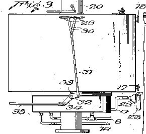
Figure 4 is a detail sectional view of one of the atomizing nozzles and its associated parts,

Figure 5 is a detail cross-sectional view showing the means for controlling the passsage of gases from the vapor-expanding chamber into the intake manifold of the engine,

Figure 6 is a perspective view of one of the valves shown in Figure 5,

Figure 7 is a cross-sectional view showing means for adjusting the valves shown in Figure 5.

Figure 8 is a cross-sectional view on line 3-3 of Figure 7.

Referring now to the drawing, the numeral 1 indicates a main vaporizing and atomizing chamber for the liquid fuel located at the bottom and communicating with a vapor heating and expanding chamber 2.
The vaporizing chamber is provided with a perforated false bottom 3 and is normally filled with liquid fuel to the level x. Atmospheric air from a conduit 4 enters the space below the false bottom 3 and passes upwardly through perforations 5 in said bottom and then bubbles up through the liquid fuel vaporizing a portion of it.
Liquid fuel for maintaining the level x in the chamber 1 passes from the usual fuel tank (not shown) through a pipe 6, and is forced by a pump 7 through a pipe 8, into and through a pair of nozzles 9 having their outlets located in the chamber 1, just above the level of the liquid fuel therein. The pump 7 may be of any approved form but is preferably of the diaphragm type, as such fuel pumps are now standard equipment on most automobiles.
The nozzles 9 are externally threaded at their lower ends to facilitate their assembly in the chamber 1 and to permit them to be removed readily, should cleaning be necesary.
The upper ends of the nozzles 9 are surrounded by Venturi tubes 10 having a baffle 11 located at their upper ends opposite the outlets of the nozzles. The liquid fuel being forced from the ends of the nozzles 9 into the restricted portions of the Vneturi tubes causes a rapid circulation of the air and vapors in the chamber through the tubes 10 and brings the air and vapors into intimate contact with the liquid fuel, with the result that a portion of the liquid fuel strikes the baffles 11 and are thereby further broken up and deflected downwardly into the upwardly flowing currnet of air and vapors.
The pump 7 is regulated to supply a greater amount of liquid fuel to the nozzles 9 than will be vaporized. The excess over that vaporized will drop into the chamber 1 and cause the liquid to be maintained at the indicated level. When the liquid fuel rises above that level, a float valve 12 will be lifted and the excess will flow through an overflow pipe 13 into a pipe 14 leading back to the pipe 6 on the intake side of the pump 7. Such an arrangement permits a large amount of liquid fuel being withdrawn from the fuel tank than is actually vaporized and consumed in the engine. As the float valve 12 will set upon the end of the outlet pipe 13 as the liquid level drops below the indicated level, there is no danger of vapors passing into the pipe 14 and hence into the pump 7 to interfere with its normal operation.
The upper end of the vaporizing and atomizing chamber 1 is open and vapors formed by the atmospheric air bubbling through the liquid fuel a the bottom of the chamber and those formed as the result of the atomization of the nozzles 9 will pass into the heating and expanding chamber 2. As is clearly shown in Figure 1, the chamber 2 comprises a series of tortuous passages 15 and 16 leading from the bottom to the top. The vapors pass through the passages 15 and the hot exhaust gases of the engine pass through the passages 16, a suitable entrance 17 and 18 being provided for that purpose.
The vapors passing upwardly in a zigzag path through the passages 15 will be brought into heat interchange relation with the hot walls of the passages 16 for the exhaust gases. The total length of the pasages 15 and 16 is such that a relatively large reserve supply of the liquid fuel is always maintained in the chamber 2, and by maintaining the vapors in heat interchange relation with the hot exhaust gases for a substantial period, the vapors will absorb sufficient heat from those gases to cause the vapors to expand, with the result that when they are withdrawn from the top of the chamber 2, they will be in the true vapor phase, and, due to their expansion, relatively light.
Any minute droplets of liquid fuel entrained by the vapors in the chamber 1 will precipitate out in the lower passages 15 and flow back into the chamber 1, or else be vaporized by heat which the vapors absorb from the hot exhaust gases in their passage through the chamber 2.
The upper end of the vapor passage 15 communicates with openings 18 adjacent the upper end of a down-draft air tube 20 leading to the intake manifold of the engine. Valves 21 are interposed in the openings 19, so that the passage of the vapors therethrough into the air tube may be controlled. The valves 11 preferably are of the rotary plug type and are controlled as hereinafter described.
Suitable means are provided for causing the vapors to be maintained in the chamber 2 under a pressure greater than atmospheric so that when the valves 21 are opened, the vapors will be forced into the air tube 20 independently of the suction of the engine. Such means may comprise an air pump (not shown) for forcing the atmospheric air through the pipe 4 into the chamber 1, beneath the false bottom 3, but I prefer merely to provide the pipe 4 with a funnel-shaped inlet end 22 and located just back of the usual fan 23 of the engine. That will cause the air to pass through the pipe 4 with sufficient force to maintain the desired pressure in the chamber 2, and the air being drawn through the radiator by the fan will be preheated prior to its introduction into the chamber 1 and hence will vaporize greater amounts of the liquid fuel. If desired, the pipe 4 may be surrounded by an electric or other heater, or exhaust gases from the engine may be passed therethrough prior to its introduction into the liquid fuel in the bottom of the chamber 1. The air tube 23 is provided with a butterfly throttle valve 24 and a choke valve 24a, as is customary with carburetors, used for internal combustion engines. The upper end of the air tube 20 extends above the chamber 2 a distance sufficient to receive an air filter and /or silencer, if desired.
A low speed or idling jet 25 has its upper end communicating with the passage through the air tube 20 adjacent the throtttling valve 24 and its lower end extending into the liquid fuel in the bottom of chamber 1 for supplying fuel to the engine when the valves are in a position such as to close the passages 19. However, the passage through the idling jet 25 is so small that under normal operation the suction thereon is not sufficient to lift liquid from the bottom of the chamber 1.
To prevent the engine from backfiring into the vapor chamber 2, the ends of the passages 15 are covered with a fine mesh screen 26 which, operating on the principle of a miner's lamp, will prevent the vapors in the chamber 2 from exploding in case of a backfire, but will not interfere subtantially with the passage of the vapors from the chamber 2 into the air tube 20 when the valves 21 are in open position . The air tube 20 preferably is in the form of a venturi with the greatest restriction being at that point where the openings 18 are located, so that when the valves 21 are opened there will be a pulling force on the vapors because of the increased velocity of the air at the restricted portion of the air tube 20 opposite the openings 19, as well as an expelling force on them due to the presence in the chamber 2.
As shown in Figure 3, the operating mechanism for the valves 21 is so connected to the operationg mechanism for the throttle valve 24 that they are opened and closed simultaneously with the opening and closing of the throttle valve, so that the amount of vapor supplied to the engine will at all times be in proportion to the demands placed upon the engine. To that end, each valve 21 has an extension or operating stem 27 protruding through one of the side walls of the vapor-heating and expanding chamber 2. Packing glands 28 of the ordinary construction surround the stems 27 where they pass through the chamber wall to prevent leakage of vapors at those points.
Operating arms 29 are rigidly secured to the outer ends of the stems 27 and extend towards each other. The arms are pivotally and adjustably connected to a pair of links 30 which at their lower ends are pivotally connected to an arm 32 rigidly secured on an outer extension 33 of the stem of the throttle valve 24. The extension 33 also has rigidly secured thereto an arm 34, to which is connected an operating link 35 leading from the means for accelerating the engine.
The means for adjustably connecting the upper ends of the links 30 to the valve stems 27 of the valves 21, so that the amount of vapors delivered from the chamber 2 may be regulated to cause the most efficient operation of the particular engine to which the carburetor is attached, comprises angular slides 36 to which the upper ends of the links 30 are fastened, and which are slidably, but non-rotatably mounted in guideways 37 in the arms 29. The slides 26 have threaded bores through which screws 33 pass. The screws 33 are rotatably mounted in the arms 29, but at held against longitudinal movement so that when they are rotated the slides 36 will be caused to move along the guideways 31 and change the relative position of the links 30 to the valve stems 27, so that a greater or less movement, and consequently a greater or less opening of the ports 19 will take place when the throttle valve 24 is operated.
For safety, and for most efficient operation of the engine, the vapors in the chamber 2 should not be heated or expanded beyond a predetermined amount, and in order to control the extent to which the vapors are heated, and consequently the extent to which they are expanded, a valve 39 is located in the exhaust passage 18 adjacent the inlet 11. The valve 39 is preferably thermostatically controlled, as, for example, by an expanding rod thermostat 40 which extends through the chamber 2. However, any other means may be provided, for reducing the amount of hot exhaust gases entering the passages 16 when the temperature of the vapors in the chamber reaches or exceeds the optimum.
The carbutetor has been described in detail in connection with a down-draft type of carburetor, but it is to be understood that its usefulness is not restricted to that particular type of carburetor, and that the manner in which the mixture of atmospheric air and vapors in introduced into the engine cylinders is immaterial as far as the advantages of the carburetor are concerned.
The term "dry vapor" is used herein to define the physical condition of the liquid fuel vapor after the removal of liquid droplets, or the mist which is frequently entrained in what is ordinarily termed a vapor.
From the foregoing description it will be seen that the present invettion provides a carburetor in which the breaking up of the liquid fuel for subsequent use is independent of the suction created by the engine, and that after the liquid fuel is broken up it is maintained under pressure in a heated space for a length of time sufficient to permit all entrained liquid particles to be separated or vaporized and to permit the dry vapors to expand prior to their introduction into, and admixture with the main volume of atmospheric air passing into the engine cylinders,.
I claim: [ Claims
not included here ]
US
Patent # 2,026,798
Carburetor
Charles N.
Pogue
(January 9, 1936)
This invention relates to carburetors suitable for use with internal combustion engines and in an improvement on the carburetors shown in my Patents # 1,938,497 and # 1,997, 497.
In my aforesaid patents an intimate contact between a liquid such as the fuel used for internal combustion engines, and a gas such as air, is obtained by causing the gas to bubble up through a body of the liquid. The vaporized liquid passes into a vapor chamber which preferably is heated, and any liquid droplets are returned to the body of liquid, with the result that the fuel introduced into the combustion chamber is free of liquid particles, and in the molecular state so that an intimate mixture with the air is obtained to give an explosive mixture from which nearer the maximum energy is contained in the liquid fuel is obtained. Moreover, as there are no liquid particles introduced into the combustion chambers there will be no burning of the fuel and consequently the temperature of the engine will not be increased above that at which it operates most efficiently.
In my patent # 1,997,497, the air which is to bubble up through the body of liquid fuel is forced into and through the fuel under pressure and the fuel vapors and air pass into a chamber where they are heated and caused to expand. The introduction of the air under pressure and the expansions of the vaporous mixture insures a sufficient pressure being maintained in the vapor heating and expanding chamber to cause at least a portion of it to be expelled therefrom into the intake manifold as soon as the valve controlling the passage thereto is opened.
In accordance with the present invention, improved means are provided for maintaining the vaporous mixture in the vapor heating chamber under a predetermined pressure, and for regulating such pressure so that it will be at the optimum for the particular conditions under which the engine is to operate. Such means preferably comprises a reciprocating pump operated by a vacuum-operated motor for forcing the vapors into and through said chamber. The pump is provided with a suitable pressure-regulating valve so that when the pressure in the vapor-heating chamber exceeds the predetermined amount a portion of the vaporous mixture will be bypassed from the outlet side to the inlet side of the pump and recirculated.
The invention will be described further in connection with the acomcpanying drawings, but such further disclosure and description is to be taken merely as an exemplification of the invention, and the same is not limited thereby except as pointed out in the subjoined claims.
In the drawings:
Figure 1 is a side elevation of a carburetor embodying the invention.

Figure 2 is a plan view thereof.

Figure 3 is an enlarged vertical sectional view.

Figure 4 is a transverse sectional view on the line 4-4 of Figure 3.

Figure 5 is a detail sectional view on line 5-5 of Figure 3.

Figure 6 is a transverse sectional view through the pump and actuating motor therefor, taken on line 6-6 of Figure 2.


Figure 8 is a longitudinal sectional view through a part of teh pump cylinder, sowing the piston in elevation.
In the accompanying drawings, a vaporizing and atomizing chamber 1 is located at the bottom of the carburetor and has an outlet at its top for the passage of fuel vapors and air into a primary vapor heating chamber 2.
The vaporizing chamber 1 is provided with a perforated false bottom 3 and is normally filled with liquid fuel to the level indicated in Figure 1. Atmospheric air from a conduit 4 is introduced into the space below the false bottom 3 and passes upwardly through the body of liquid fuel below the false bottom 3, and then through the perforations 5 in said false bottom, which breaks it up into a myriad of fine bubbles, which pass upwardly through the liquid fuel above the false bottom.
Liquid fuel for maintaining the level indicated in the chamber 1 passes from the usual fuel tank (not shown) through pipe 6, and is forced by a pump 7 through a pipe 6 into and through a pair of nozzles 9 having their outlets located in the chamber 1, just above the level of the liquid fuel therein. The pump 7 may be of any approved form but is preferably of the diaphragm type, as such fuel pumps are now standard equipment.
The nozzles 9 are externally threaded at their lower ends to facilitate their assembly in the chamber 1 and to permit them to be removed readily, should cleaning be necessary.
The upper ends of the nozzles 9 are surrounded by Venturi tubes 10 having baffles 11 located at their upper ends opposite the outlets of the nozzles, as is shown and described in detail in my aforesaid Patent # 1,997,497. The liquid fuel being forced from the ends of the nozzles 9 into the restricted portions of the tubes 10 causes a rapid circulation of the air and vapors in the chamber through the tubes 10 and brings the air and vapors into intimate contact with the liquid fuel, with the result that a portion thereof is vaporized. Unvaporised portions of the liquid fuel strike the baffles 11 and are thereby further broken up and deflected downwardly into the upwardly flowing current of air and vapors.
The pump 7 is regulated to supply a greater amount of liquid fuel to the nozzles 9 than will be vaporized. The excess over that vaporized will drop into the chamber 1 and cause the liquid to be maintained at the indicated level. when the liquid fuel rises above that flat level, a float valve 12 will be lifted and the excess will flow through an overflow pipe 13 into a pipe 14 leading back to the pipe 6 on the intake side of the pump 7. Such an arrangement permits a large amount of liquid fuel to be circulated by the pump 7 without more fuel being withdrawn from the fuel tank than is actually vaporized and consumed in the engine. As the float valve 12 will set upon the end of the outlet pipe 19 as soon as the liquid level drops below the indicated level, there is no danger of vapors passing into the pipe 14 and hence into the pump 7 to interfere with its normal operation.
The amount of liquid fuel vaporized by the nozzles 9 and by the passage of air through the liquid body thereof is sufficient to provide a suitably enriched vaporous mixture for introducing into the passage leading to the intake manifold of the engine through which the main volume of atmospheric air passes.
Vapors formed by the atmospheric air bubbling through the liquid fuel in the bottom of the chamber 1 and those formed as the result of the atomization at the nozzles 9 pass from the top of that chamber into the primary heating chamber 2. As is clearly shown in Figure 1, the chamber 2 comprises a relatively long spiral passage 15 through which the vaporous mixture gradually passes inwardly to a central outlet 16 to which is connected a conduit 17 leading to a reciprocating pump 18 which forces the vaporous mixture under pressure into a conduit 19 leading to a central inlet 20 of a secondary heating chamber 21 which like the primary heating chamber comprises a relatively long spiral. The vaporous mixture gradually passes outwardly through the spiral chamber 21 and enters a downdraft air tube 22, leading to the intake manifold of the engine, through an outlet 23 controlled by a rotary plug valve 24.
To prevent the engine from backfiring into the vapor chamber 2, the ends of the passages 19 are covered with a fine mesh screen 25, which, operating on the principle of a miner's lamp, will prevent the vapors in the chamber 2 from exploding in case of a backfire, but will not interfere substantially with the passage of the vapors from the chamber 21 into the air tube 22 when the valve 24 is in open position. The air tube 22 preferably is in the form of a venturi with the greatest restriction being at that point where the outlet 23 is located, so that when the valve 34 is opened there will be a pulling force on the vaporous mixture due to the increased velocity of the air at the restricted portion of the air tube opposite the outlet 23, as well as an expelling force on them due to the pressure maintained in the chamber 21 by the pump 18.
Both the primary and secondary spiral heating chambers 15 and 21 and the central portion of the air tube 22 are enclosed by a casing 26 having an inlet 27 and an outlet 28 for a suitable heating medium such as the gaseous products of cumbustion from the exhaust manifold.
The pump 18 for forcing the vaporous mixture from the primary heating chamber 2 into and through the secondary chamber 21 includes a working chamber 29 for a hollow piston 30 provided with an inlet 31 contolled by a valve 32, and an outlet 33 controlled by a valve 34. The end of the working chamber 29 to which is connected the conduit 17, which conducts the vaporous mixture from the primary heating chamber 2, has an inlet valve 35, and the opposite end of the working chamber has an outlet 36 controlled by a valve 37 positioned in an auxiliary chamber 38, to which is connected the outlet pipe 19 which conducts the vaporous mixture under pressure to the secondary heating chamber 21. Each of the valves 32, 34, 35 and 37 is of the one-way type. They are shown as being gravity-actuated flap valves, but it will be understood that spring-pressured or other types of one-way valves may be used if desired.
One side of the piston 30 is formed with a gear rack 39 which is received in a groove 39a of the wall forming the cylinder of the pump. The gear rack 39 engages with an actuating spur grear 40 carried on one end of the shaft 41 and operating in a housing 32 formed on the pump cylinder. The other end of the shaft 41 carries a spur gear 43, which engages and is operated by a gear rack 44 carried on a piston 46 of a double-acting motor 47. The particular construction of the double-acting motor 47 is not material, and it may be of a vacuum type commonly used on automobiles, in which case a flexible hose 49 would be connected with the intake manifold of the engine to provide the encessary vacuum for operating the piston 45.
Under the influence of the double-acting motor 47, the piston 30 of the pump has a reciprocatory movement in the working chamber 29. Movement of the piston towards the left in Figure 7 tends to compress the vaporous mixture in the working chamber between the end of the piston and the inlet from the pipe 17, and causes the valve 35 to be forced tightly against the inlet opening. In a like manner, the valves 32 and 24 are forced open and vaporous mixture in that portion of the working chamber is forced theough the inlet 31 in the end of the piston 30, into the interior of the piston, where it displaces the vaporous mixture there and forces it into the space between the right-hand end of the piston and the right-hand end of the working chamber. The passage of the vaporous mixture into the right-hand end of the working chamber is supplemented by the partial vacuum created there when the piston moves toward the left. During such movement of the piston, the valve 37 is maintained closed and prevents any sucking back of the vaporous mixture from the secondary heating chamber 21.
When the motor 47 reverses, the piston 30 moves to the right and the vaporous mixture in the right-hand end of the working chamber is forced past the valve 37 and through the pipe 18 into the secondary heating chamber 21. At the same time, a vacuum is created behind the piston 30 and results in the left-hand end of the working chamber again being filled with the vaporous mixture from the primary heating chamber 2.
As the operation of the pump 47 will vary in accordance with the suction created in the intake manifold, it preferably is regulated to actuate the pump at such a speed that the vaporous mixture will always be pumped into the secondary heating chamber at a rate sufficient to maintain a greater pressure there than is desired. In order that the pressure in the working chamber may at all times be maintained at the optimum, a pipe 50 having an adjustable pressure-regulating valve 51 is connected across the inlet and outlet pipes 17 and 19. The valve 51 will permit a portion of the vaporous mixture discharged from the pump to be bypassed to the inlet 17 so that a pressure, predetermined by the seating of the valve 51, will at all times be maintained in the second heating chamber 21.
The air tube 22 is provided with a butterfly throttle valve 52 and a choke valve 53, as is usual with carburetors adapted for use with internal combustion engines. Operating stems 54, 55, 56 for the valves 52, 53, and 24 respectively, extend through the casing 26. An operating arm 57 is fixed securely to the outer end of the stem, 54 and is connected to a rod 55 which extends to the dashboard of the automobile or some other place conveniently located to the driver of the automobile. The outer end of the stem 56 of the valve 24 which controls the outlet 23 from the secondary heating chamber 21 has one end of an operating arm 59 fixedly secured thereto. The other end of the arm 59 is pivotally connected to a link 60 which extends downwardly and pivotally connects to one end of a bell crank lever 61, fixedly secured to the end of the stem 54 of the throttle valve 52. The other end of the bell crank lever 61 is connected to an operating rod 62 which, like the rod 53, extends to a place conveniently located to the driver. The valves 24 and 52 are connected for simultaneous operation so that when the throttle valve 52 is opened to increase the speed of the engine the valve 24 will be opened to admit a larger amount of the heated vaporous mixture from the secondary heating chamber 21.
While the suction created by the pump ordinarily will create a sufficient vacuum in the primary heating chamber 2, to cause atmospheric air to be drawn into and upwardly through the body of liquid fuel in the bottom of the vaporizing chamber 1, in some instances it may be desirable to provide supplemental means for forcing the atmospheric air into and through said body of liquid and in such case an auxiliary pump may be provided for that purpose, or the air conduit may be provided with a funnel-shaped intake which is positioned behind the fan which is customarily placed behind the radiator of the engine.
The foregoing description has been given in connection with a downdraft type of carburetor, but it is to be understood that the invention is not limited to use with such type carburetors and that the manner in which the mixture of atmospheric air and vapors is introduced into the engine cylinders is immaterial as far as the advantages of the carburetor are concerned.
Before the carburetor is put into use the pressure-regulating valve 51 in the bypass pipe 58 will be adjusted so that the pressure best suited for conditions under which the engine is to operate will be maintained in the secondary heating chamber 21. When the valve 51 has thus been set and the engine started, the pump will create a partial vacuum in the primary heating chamber 2 and cause atmospheric air to be drawn through the conduit 4 and to bubble upwardly through the liquid in the bottom of the vaporizing and atomizing chamber 1 with resultant vaporization of a part of the liquid fuel therein. At the same time, the pump will be set into operation and liquid fuel will be pumped from the fuel tank through the nozzles 9 which will result in an additional amount of the fuel being vaporized. The vapors resulting from such atomization of the liquid fuel and the passage of the air through the body of the liquid will pass into and through the spiral chamber 1 where they will be heated by the products of combustion in the surrounding chamber formed by the casing 26. The fuel vapors and air will gradually pass inwardly to the outlet 16 and thence through the conduit 17 to the pump 18 which will force them into the secondary heating chamber 21 in which they will be maintained at the predetermined pressure by the pressure-regulating valve 51. The vaporous mixture is further heated in the chamber 21 and passes spirally outwardly to the valve-controlled outlet 23 which opens into the air tube 22 which conducts the main volume of atmospheric air to the intake manifold of the engine.
The heating of the vaporous mixture in the heating chambers 2 and 21 tends to cause them to expand, but expansion in the chamber 21 is prevented due to the pressure maintained in that chamber by the regulating valve 51. However, as soon as the heated vaporous mixture passes the valve 24 and is introduced into the air flowing through the intake tube 22, it is free to expand and thereby become relatively light so that a more intimate mixture with the air is obtained prior to the mixture being exploded in the engine cylinders. Thus it will be seen that the present invention not only provides means wherein the vaporous mixture from the heating chamber 21 is forced into the air passing through the air tube 22 by a positive force, but is is also heated to such an extent that after it leaves the chamber 21 it will expand to such an extent as to have a density less than it would if introduced directly from the vaporizing and atomizing chamber 1 into the air tube 22.
The majority of the liquid particles entrained by the vaporous mixture leaving the chamber 1 will be separated in the first half of the outermost spiral of the primary heating chamber 2 and drained back into the body of liquid in the tank. Any liquid particles which are not thus separated will be carried on with the vaporous mixture and due to the circulation of that mixture and the application of heat, will be vaporized before the vaporous mixture is introduced into the air tube 22 from the secondary heating chamber 21. Thus "dry" vapors only are introduced into the engine cylinders and any burning of liquid particles of the fuel in the engine cylinder, which would tend to raise the temperature of the engine above that at which it operates most efficiently is avoided.
While the fullest benefits of the invention are obtained by using both a primary and a secondary heating chamber, the primary heating chamber may, if desired, be eliminated, and the vaporous mixture pumped directly from the vaporizing and atomizing chamber into the spiral heating chamber 21.
From the foregoing invention it will be seen that the present invention provides an improvement over the carburetor disclosed in my patent # 1,997,497, in that it is possible to maintain the vaporous mixture in the heating chamber 21 under a predetermined pressure, and that as soon as the vaporous mixture is introduced in the main supply of the engine, it will expand and reach a density at which it will form a more intimate mixture with the air. Furthermore, the introduction of the vaporous mixture into the air stream in the tube 22 causes a certain amount of turbulence which also tends to give a more intimate mixture of the vapor molecules with the air.
I claim: [ Claims not included here ]