Andrija PUHARICH
Water Decomposition by AC Electrolysis
Dr Andrija Puharich reportedly drove his motor home for hundreds of thousands of miles around North America in the 1970s using only water as fuel. At a mountain pass in Mexico, he collected snow for water. Here is the only article he wrote on the subject, plus his patent:
Cutting The Gordian Knot of the Great Energy
Bind
by Andrija Puharich
(1) Introduction
It is hardly necessary to weigh the value of the World Energy bank account for any sophisticated person, these days. It is grim. The oil reserves will dwindle away in a score of years or so, and the coal reserves will be gone in some twelve score years. ( Ref. 1)
This is not to say that the outlook is hopeless. There is an abundance of alternative energy sources, but the economics of development and exploitation present an enormous short term strain on the world political and banking resources.
Visionary scientists tell us that the ideal fuel in the future will be as cheap as water, that it will be non toxic both in its short term, and in its long term, effects, that it will be renewable in that it can be used over and over again, that it will be safe to handle, and present minimal storage and transportation problems and costs. And finally that it will be universally available anywhere on earth.
What is this magical fuel, and why is it not being used? The fuel is water. It can be used in its fresh water form. It can be used in its salt water form. It can be used in its brackish form. It can be used in its snow and ice form. When such water is decomposed by electrolytic fission into hydrogen and oxygen gases, it becomes a high energy fuel with three times the energy output which is available from an equivalent weight of high grade gasoline.
(Ref. 1 ) The interested reader should refer to the special issue of National Geographic, "Energy", February 1981.
Then why is water not being used as a fuel? The answer is simple. It costs too much with existing technology to convert water into gases hydrogen and oxygen. The basic cycle of using water for fuel is described in the following two equations, familiar to every high school student of Chemistry:
H2O Electrolysis + 249.68 Btu Delta G ==> H2 + (1/2)O2 per mole of water (1 mole = 18 gms.). (1)
This means that it requires 249.688 Btu of energy (from electricity) to break water by electrocal fission into the gases hydrogen and oxygen.
H2 and (1/2)O2 === catalyst ===> H2O - Delta H 302.375 Btu per mole of water. (2)
This means that 302.375 Btu of energy (heat or electricity) will be released when the gases, hydrogen and oxygen, combine. The end product (the exhaust) from this reaction is water. Note that more energy (under ideal conditions) is released from combining the gases than is used to free them from water. It is know that under ideal conditions it is possible to get some 20% more energy out of reaction (2) above, then it takes to produce the gases of reaction (1) above. Therefore, if reaction (1) could be carried out at 100% efficiency, the release of energy from reaction (2) in an optimally efficient engine (such as a low temperature fuel cell), there would be a net energy profit which would make the use of water as a fuel an economically feasible source of energy .
The cost of producing hydrogen is directly related to the cost of producing electricity. Hydrogen as produced today is generally a byproduct of off-peak-hour electrical production in either nuclear or hydroelectric plants. The electricity thus produced is the cheapest way of making hydrogen. We can compare the cost of production of electricity and the cost of producing hydrogen. The following table is adapted from Penner (Ref. 2) whose data source is based on Federal Power Commission, and American Gas Association Figures of 1970 and on a 1973 price evaluation (just before OPEC oil price escalation.)
Table 1: Relative Prices in Dollars per 106 Btu . See Appendix 1 for definition of British Thermal units (a) @ 9.1 mils/kWh
Cost Component ~ Electricity
~ Electrolytically-Produced H
Production
~ 2.67 (b) ~ 2.95 to 3.23 (b)
Transmission
~ 0.61 ~ 0.52 (c)
Distribution
~ 1.61 ~ 0.34
Total
Cost ~ $4.89 ~ $3.81 to $4.09
If we compare only the unit cost of production of electricity vs Hydrogen from the above table:
106 Btu H2 / 106 Btu El = $3.23 / $2.67, or 20.9% higher cost, H2
(Ref. 2) Penner, S.S. & L. Iceman: Non Nuclear Technologies, Vol II, Addison-Wesley Publishing Company, 1977, Chap. 11, and Table 11.1-2 (Page 132).
It must also be noted that the price of natural gas is much cheaper than either electricity or hydrogen, but because of the price fluctuations due to recent deregulation of gas. It is not possible to present a realistic figure.
In the opinion of Penner (op. cit.), if the hydrogen production cost component of its total cost could be reduced three fold, it would become a viable alternate energy source. In order to achieve such a three-fold reduction in production costs, several major breakthroughs would have to occur.
(1) ENDERGONIC REACTION ~ (1) supra. A technological breakthrough that permits 100% conversion efficiency of water by electrolysis fission into the two gases, Hydrogen as fuel and Oxygen as oxidant.
(2) HYDROGEN PRODUCTION, in situ. A technological breakthrough that eliminates the need and cost of hydrogen liquefaction and storage, transmission, and distribution, by producing the fuel in situ, when and where needed.
(3) EXERGONIC REACTION ~ (2) supra. A technological breakthrough which yields a 100% efficient energy release from the combination of hydrogen and oxygen into water in an engine that can utilize the heat, steam, or electricity thus produced.
(4) ENGINE EFFICIENCY. By a combination of the breakthroughs outlined above, (1), (2), and (3) utilized in a highly efficient engine to do work, it is possible to achieve a 15% to 20% surplus of energy return over energy input, theoretically.
It is of interest to record that a new invention is now being developed to realise the above outlined goal of cheap, clean renewable and high grade energy.
A Thermodynamic Device has been invented which produces hydrogen as fuel, and oxygen as oxidant, from ordinary or from sea water, eliminating the cost and hazard of liquefaction, storage, transmission, and distribution. The saving of this aspect of the invention alone reduces the total cost of hydrogen by about 25%.
This Thermodynamic Device is based on a new discovery --- the efficient electrolytic fission of water into hydrogen gas and oxygen gas by the use of low frequency alternating currents as opposed to the conventual use of direct current, or ultra-high frequency current today. Such gas production from water by electrolytic fission approaches 100% efficiency under laboratory conditions and measurements. No laws of physics are violated in this process.
This Thermodynamic Device has already been tested at ambient pressures and temperatures from sea level to an altitude of 10,000 feet above sea level without any loss of its peak efficiency. The device produces two types of gas bubbles; one type of bubble contains hydrogen gas; the other type contains oxygen gas. The two gases are thereafter easily separable by passive membrane filters to yield pure hydrogen gas, and pure oxygen gas.
The separate gases are now ready to be combined in a chemical fusion with a small activation energy such as that from a catalyst or an electrical spark, and yield energy in the form of heat, or steam, or electricity --- as needed .When the energy is released by the chemical fusion of hydrogen and oxygen, the exhaust product is clean water. The water exhaust can be released into nature and then renewed in its energy content by natural processes of evaporation, solar irradiation in cloud form, an subsequent precipitation as rain on land or sea, and then collected again as a fuel source. Or, the exhaust water can have its energy content pumped up by artificial processes such as through solar energy acting through photocells. Hence, the exhaust product is both clean and renewable. The fuel hydrogen, and the oxidant oxygen, can be used in any form of heat engine as an energy source if economy is not an important factor. But the practical considerations of maximum efficiency dictate that a low temperature fuel cell with its direct chemical fusion conversion from gases to electricity offers the greatest economy and efficiency from small power plants (less than 5 kilowatts).
For large power plants, steam and gas turbines are the ideal heat engines for economy and efficiency. With the proper engineering effort, automobiles could be converted rather easily to use water as the main fuel source.
(2) A Elementry Introduction to the Design & Operation of the Thermodynamic Device to Electrolyse Water with AC ~
The Thermodynamic Device (TD) is made up of three principal components: An electrical function generator, Component I, that energizes a water cell, the TD, Component II and Component III , a weak electrolyte.
COMPONENT I: The Electrical Function Generator ~ See Fig 1.
Figure 1: Signal Generator Component Block ~

This electronic device has a complex alternating current output consisting of an audio frequency (range 20 to 200 Hz) amplitude modulation of a carrier wave (range: 200 to 100,000 Hz). The output is connected by two wires to Component II at the center electrode, and at the ring electrode. See Fig1. The impedance of this output signal is continuously being matched to the load which is the water solution in Component II.
COMPONENT II: The Thermodynamic Device (TD). See Figure 2.
Figure 2: Thermodynamic Device (TD) ~
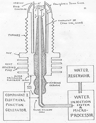
The TD is fabricated of metals and ceramic in the geometric form of a coaxial cylinder made up of a centered hollow tubular electrode which is surrounded by a larger tubular steel cylinder. These two electrodes comprise the coaxial electrode system energised by Component I. The space between the two electrodes is, properly speaking, Component III which contains the water solution to be electrolysed. The center hollow tubular electrode carries water into the cell, and is further separated from the outer cylindrical electrode by a porous ceramic vitreous material. The space between the two electrodes contains two lengths of tubular Pyrex glass, shown in Figures 2 and 3. The metal electrode surface in contact with the water solution are coated with a nickel alloy.
COMPONENT III: the weak electrolyte water solution. Fig.3
Figure 3: The Water Cell Section of Component II ~
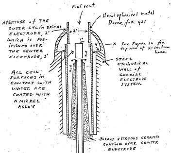
This consists of the water solution, the two glass tubes, and the geometry of the containing wall of Component II. It is the true load for Component I, and its electrode of Component II.
The Component III water solution is more properly speaking, ideally a 0.1540 M Sodium Chloride solution, and such is a weak electrolyte. In figure 4 we show the hypothetical tetrahedral structure of water molecule, probably in the form in which the complex electromagnetic waves of Component I to see it. The center of mass of this tetrahedral form is the oxygen atom. The geometric arrangement of the p electrons of oxygen probably determine the vectors i (L1) and i (L2) and i (H1) and i (H2) which in turn probably determine the tetrahedral architecture of the water molecule. The p electron configuration of oxygen is shown in Figure 5. Reference to Figure 4 shows that the diagonal of the right side of the cube has at its corner terminations the positive charge hydrogen (H+) atoms; and that the left side of the cube diagonal has at its corners the lone pair electrons, (e-). It is to be further noted that this diagonal pair has an orthonormal relationship.
Figure 4: The Water Molecule in Tetrahedral Form ~
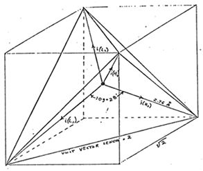
Hydrogen bonding occurs only along the four vectors pointing to the four vertices of a regular tetrahedron, and in the above drawing we show the four unit vectors along these directions originating from the oxygen atoms at the center. i(H1) and i(H2) are the vectors of the hydrogen bonds formed by the molecule i as a donor molecule. These are assigned to the lone pair electrons. Molecules i are the neighboring oxygen atoms at each vertex of the tetrahedron.
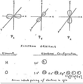
Figure 5: Electron Orbitals ~
(3) Electrothermodynamics ~
We will now portray the complex electromagnetic wave as the tetrahedral water molecule sees it. The first effect felt by the water molecule is in the protons of the vectors, i (H1) and i (H2). These protons feel the 3 second cycling of the amplitude of the carrier frequency and its associated side bands as generated by Component I. This sets up a rotation moment of the proton magnetic moment which one can clearly see on the XY plot of an oscilloscope, as an hysteresis loop figure. However, it is noted that this hysteresis loop does not appear in the liquid water sample until all the parameters of the three components have been adjusted to the configuration which is the novel basis of this device. The hysteresis loop gives us a vivid portrayal of the nuclear magnetic relaxation cycle of the proton in water.
The next effect felt by the water molecule is the Component I carrier resonant frequency, Fo. At the peak efficiency for electrolysis the value of Fo is 600 Hz +/- 5 Hz.
This resonance however is achieved through control of two other factors. The first is the molal concentration of salt in the water. This is controlled by measuring the conductivity of the water through the built in current meter of Component I. There is maintained an idea ratio of current to voltage I/E = 0.01870 which is an index to the optimum salt concentration of 0.1540 Molal.
The second factor which helps to hold the resonant which helps to hold the resonant frequency at 600 Hz is the gap distance of Y, between the centre electrode, and the ring electrode of Component II.
This gap distance will vary depending on the size scale of Component II, but again the current flow, I, is used to set it to the optimal distance when the voltage reads between 2.30 (rms) volts, at resonance Fo, and at molal concentration, 0.1540. The molal concentration of the water is thus seen to represent the electric term of the water molecule and hence its conductivity.
The amplitude modulation of the carrier gives rise to side bands in the power spectrum of the carrier frequency distribution. It is these side bands which give rise to an acoustic vibration of the liquid water, and it is believed to the tetrahedral water molecule. The importance of the phonon effect --- the acoustic vibration of water in electrolysis --- was discovered in a roundabout way. Research work with Component I had earlier established that it could be used for the electro-stimulation of hearing in humans. When the output of Component I is comprised of flat circular metal plates applied to the head of normal hearing humans, it was found that they could hear pure tones and speech. Simultaneously, acoustic vibration could also be heard by an outside observer with a stethoscope placed near one of the electrodes on the skin. It was observed that the absolute threshold of hearing could be obtained at 0.16 mW (rms), and by calculation that there was an amplitude of displacement of the eardrum of the order of 10-11 and a corresponding amplitude of the cochlear basilar membrane of 10-13 meter. Corollary to this finding. I was able to achieve the absolute reversible threshold of electrolysis at a power level of 0.16 mW (rms). By carrying out new calculations I was able to show that the water was being vibrated with a displacement of the order of 1 Angstrom ( = 10-10 meters). This displacement is of the order of the diameter of the hydrogen atom.
Thus it is possible that the acoustic phonons generated by audio side bands of the carrier are able to vibrate particle structures within the unit water tetrahedron.
We now turn to the measurement problem with respect to efficiency of electrolysis. There are four means that can be used to measure the reactant product of water electrolysis . For simple volume measurements one can use a precision nitrometer such as the Pregl type. For both volume and quantitative analysis one can use the gas chromatography with thermal conductivity detector. For a continuous flow analysis of both volume and gas species the mass spectrometer is very useful. For pure thermodynamic measurements the calorimeter is useful. In our measurements, all four methods were examined, and it was found that the mass spectrometer gave the most flexibility and the greatest precision. In the next section we will describe our measurement using the mass spectrometer.
Protocol
(4) Methodology for the Evaluation of the Efficiency of Water Decomposition by Means of Alternating Current Electrolysis ~
Introduction ~
All systems used today for the electrolysis of water into hydrogen as fuel, and oxygen as oxidant apply direct current to a strong electrolyte solution. These systems range in efficiency from 50% to 71%. The calculation of energy efficiency in electrolysis is defined as follows:
"The energy efficiency is the ration of the energy released from the electrolysis products formed (when they are subsequently used) to the energy required to effect electrolysis." (Ref. 1)
The energy released by the exergonic process under standard conditions
H2(g) + (1/2) O2(g) ===> H2O = 3 02.375 Btu
which is 68.315 Kcal/mol. or, 286,021 Joules/mol, and is numerically equal to the enthalphy charge (Delta H ) for the indicated process. On the other hand the minimum energy (or useful work input) required at constant temperature and pressure for electrolysis equals the Gibbs free energy change (Delta G). (Ref 2)
(Ref. 1) S.S. Penner and L. Iceman: Energy. Volume II , Non Nuclear Energy Technologies. Adison Wesley Publishing Company, Inc.Reading Massachusetts, 1977 (Rev. Ed. ) chapter 11.
(Ref. 2) S.S. Penner: Thermodynamics, Chapter 11, Addison-Wesley Publishing Co. Reading, Massachusetts, 1968.
Penner shows (op.cit.) that there is a basic relation derivable from the first and second laws of thermodynamics for isothermal changes which shows that
Delta G = Delta H - T Delta S (2)
where Delta S represents the entropy change for the chemical reaction and T is the absolute temperature.
The Gibbs free energy change (Delta G) is also related to the voltage (e) required to implement electrolysis by Faraday's equation,
e = (Delta G / 23.06 n ) volts (3)
where Delta G is in Kcal/mol, and n is the number of electrons (or equivalents) per mole of water electrolysed and has the numerical value 2 in the equation (endergonic process),
H2O ===> H2 (g) + (1/2)O2 (g) + 56.620 kcal or + 249.68 Btu (4)
Therefore, according to equation (2) at atmospheric pressure, and 300 degrees K , Delta H = 68.315 kcal/mol or H2O, and Delta G = 56.620 kcal / mol of H2O = 236,954 J/mol H20 for the electrolysis of liquid water.
In view of these thermodynamic parameters for the electrolysis of water into gases, hydrogen and oxygen, we can establish by Eq.(2) numeric values where,
Delta G = 236.954 J/mol H2O
under standard conditions. Thus
n = Delta G (J/mol) / Delta Ge (J/mol) = <1 (5)
where Delta Ge is the electrical energy input to H2O (1) in Joules, and Delta G is the Gibbs free energy of H2O. The conversion between the two quantities is one Watt second (Ws) = one Joule.
Or, in terms of gas volume, as hydrogen, produced and measured,
n = Measured H2 (cc) / Ideal H2 (cc) = <1 (6)
In accordance with these general principles we present the methodology followed in evaluating the electrolytic of alternating current on H2O in producing the gases, hydrogen and oxygen. No attempt has been made to utilize these gases according to the process of Eq.(1). It is to be noted that the process
H2 (g) + (1/2)O2 (g) ===> H2O (g) (7)
yields only 57.796 kcal /mol. Eq.(7) shows that per mole of gases water formed at 300° K, the heat released is reduced from the 68.315 kcal/mol at Eq. (1) by the molar heat of evaporation of water at 300° K (10.5 kcal) and the overall heat release is 57.796 kcal/mol if H2O (g) is formed at 300° K. (Ref. 1)
In the following sections we describe the new method of electrolysis by means of alternating current, and the exact method and means used to measure the endergonic process of Eq.(4) and the governing Eq.(2) and Eq.(5).
(Ref. 1) Op.cit., Ref. (1) page 3. page 299ff.
(5) Thermodynanic Measurement ~
In order to properly couple Component II to a mass spectrometer one requires a special housing around Component II that it will capture the gases produced and permit these to to be drawn under low vacuum into the mass spectometer. Therefore a stainless steel and glass chamber was built to contain Component II, and provision made to couple it directly through a CO2 watertrap to the mass spectrometer with the appropriate stainless steel tubing. This chamber is designated as Component IV. Both the mass spectrometer and Component IV were purged with helium and evacuated for a two hour period before any gas samples were drawn. In this way contamination was minimized. The definitive measurement were done at Gollob Analytical Services in Berkeley Heights, New Jersey
We now describe the use of Component I and how its energy output to Component II is measured. The energy output of Component I is an amplitude modulated alternating current looking into a highly non-linear load, i.e., the water solution. Component I is so designed that at peak load it is in resonance across the system --- Components I, II, and III --- and the vector diagrams show that the capacitive reactance, and the inductance reactance are almost exactly 180° out of phase, so that the net power output is reactive (the dissipative power is very small). This design ensures minimum power lossses across the entire output system. In the experiments to be described, the entire emphasis is placed on achieving the maximum gas yield (credit) in exchange for the minimum applied electrical energy.
The most precise way to measure the applied energy from Component I to Component II and Component III is to measure the power, P, in watts, W. Ideally this should be done with a precision wattmeter. But since we were interested in following the voltage and current separately, it was decided not to use the watt meter. Separate meters were used to continuously monitor the current and the volts.
This is done by precision measurement of the volts across Component III as root mean square (rms) volts; and the current flowing in the system as rms amperes. Precisely calibrated instruments were used to take these two measurements. A typical set of experiments using water in the form of 0.9% saline solution 0.1540 molar to obtain high efficiency hydrolysis gave the following results:
rms Current = I = 25mA to 38 mA (0.025 A to 0.038 A.)
rms Volts = E = 4 Volts to 2.6 Volts
The resultant ration between current and voltage is dependent on many factors such as the gap distance between the center and ring electrodes, dielectric properties of the water, conductivity properties of the water, equilibrium states, isothermal conditions, materials used, and even the pressure of clathrates. The above current and voltage values reflect the net effect of various combinations of such parameters. When one takes the product of rms current, and rms volts, one has a measure of the power, P in watts.
P = I x E = 25 mA x 4.0 volts =100 mW (0.1 W)
and P = I x E =38 mA x 2.6 volts = 98.8 mW (0.0988 W)
At these power levels (with load), the resonant frequency of the system is 600 Hz (plus or minus 5 Hz) as measured on a precision frequency counter. The wave form was monitored for harmonic content on an oscilloscope, and the nuclear magnetic relaxation cycle was monitored on an XY plotting oscilloscope in order to maintain the proper hysteresis loop figure. All experiments were run so that the power in watts, applied through Components I, II, and III ranged between 98.8 mW to 100 mW.
Since by the International System of Units 1971 (ST), one Watt-second (Ws) is exactly equal to one Joule (J), our measurements of efficiency used these two yardsticks (1 Ws = 1J) from the debit side of the measurement.
The energy output of the system is, of course, the two gases, Hydrogen (H2) and Oxygen, (1/2)O2, and this credit side was measured in two laboratories, on two kinds of calibrated instruments, namely gas chromatography machine, and mass spectrometer machine.
The volume of gases H2 and (1/2)O2 was measured as produced under standard conditions of temperature and pressure in unit time, i.e., in cubic centimeters per minute (cc/min), as well as the possibility contaminating gases,such as air oxygen, nitrogen and argon, carbon monoxide, carbon dioxide, water vapor, etc.
The electrical and gas measurements were reduced to the common denominator of Joules of energy so that the efficiency accounting could all be handled in one currency. We now present the averaged results from many experiments. The standard error between different samples, machines, and locations is at +/- 10%, and we only use the mean for all the following calculations.
II. Thermodynamic Efficiency for the Endergonic Decomposition of Liquid Water (Salininized) to Gases Under Standard Atmosphere ( 754 to 750 m.m. Hg) and Standard Isothermal Conditions @ 25° C = 77° F = 298.16° K, According to the Following Reaction:
H20 (1) _> H2(g) + (1/2)O2(1) + Delta G = 56.620 Kcal /mole (10)
As already described, Delta G is the Gibbs function. We convert Kcal to our common currency of Joules by the formula, One Calorie = 4.1868 Joules
Delta G = 56.620 Kcal x 4.1868 J = 236,954/J/mol of H2O where1 mole = 18 gr. (11)
Delta Ge = the electrical energy required to yield an equivalent amount of energy from H2O in the form of gases H2 and (1/2)O2.
To simplify our calculation we wish to find out how much energy is required to produce the 1.0 cc of H2O as the gases H2 and (1/2)O2. There are (under standard conditions) 22,400 cc = V of gas in one mole of H2O. Therefore
Delta G / V = 236,954 J / 22,400 cc = 10.5783 J/cc. (12)
We now calculate how much electrical energy is required to liberate 1.0 cc of the H2O gases (where H2 = 0.666 parts, and (1/2)O2 = 0.333 parts by volume) from liquid water. Since P = 1 Ws= 1 Joule , and V = 1.0 cc of gas = 10.5783 Joules, then
PV = 1 Js x 10.5783 J = 10.5783 Js, or, = 10.5783 Ws (13)
Since our experiments were run at 100 mW ( 0.1 W) applied to the water sample in Component II, III, for 30 minutes, we wish to calculate the ideal (100% efficient) gas production at this total applied power level. This is,
0.1 Ws x 60 sec x 30 min = 180,00 Joules (for 30 min.). The total gas production at ideal 100% efficiency is 180 J/10.5783 J/cc = 17.01 cc H2O (g)
We further wish to calculate how much hydrogen is present in the 17.01 cc H2O (g).
17.01 cc H2O (g) x 0.666 H2 (g) = 11.329 cc H2(g) (14)
17.01 cc H2O (g) x 0.333 (1/2)O2 (g) = 5.681 cc (1/2) O2 (g)
Against this ideal standard of efficiency of expected gas production, we must measure the actual amount of gas produced under: (1) Standard conditions as defined above, and (2) 0.1 Ws power applied over 30 minutes. In our experiments, the mean amount of H2 and (1/2)O2 produced, as measured on precision calibrated GC, and MS machines in two different laboratories, where SE is +/- 10%, is,
Measured
Mean = 10.80 cc H2 (g)
Measured
Mean = 5.40 cc (1/2) cc (1/2)O2 (g)
Total Mean
= 16.20 cc H2O (g)
The ratio, n, between the ideal yield, and measured yield,
Measured H2 (g) / Ideal H2 (g) = 10.80 cc / 11.33 cc = 91.30%
(6) Alternative Methodology for Calculating Efficiency Based on the Faraday Law of Electrochemistry ~
This method is based on the number of electrons that must be removed, or added to decompose, or form one mole of, a substance of valence one. In water H2O, one mole has the following weight:
H = 1.008 gr /mol
H = 1.008 gr
/mol
O = 15.999
gr/mol
Thus, 1 mol
H2O = 18.015 gr/mol
For a unvalent substance one gram mole contains 6.022 x 10⁻²³ electrons = N = Avogadro's Number. If the substance is divalent, trivalent, etc., N is multiplied by the number of the valence. Water is generally considered to be of valence two.
At standard temperature and pressure (STP) one mole of a substance contains 22.414 cc, where Standard temperature is 273.15° K = 0° C = T . Standard Pressure is one atmosphere = 760 mm Hg = P.
One Faraday (1F) is 96,485 Coulombs per mole (univalent).
One Coulomb (C) is defined as:
1 N / 1 F = 6.122 x 10²³ Electrons / 96,485 C = one C
The
flow of one C/second = one Ampere.
One C x one
volt = one Joule second (Js).
One Ampere
per second @ one volt = one Watt = one Joule.
In alternating current, when amps (I) and Volts (E) are expressed in root mean squares (rms), their product is Power.
P = IE watts.
With these basic definitions we can now calculate efficiency of electrolysis of water by the method of Faraday is electrochemistry.
The two-electron model of water requires 2 moles of electrons for electrolysis (2 x 6.022 x 1023 ), or two Faraday quantities (2 x 96,485 = 192,970 Coulombs).
The amount of gas produced will be:
H2 = 22,414 cc /mol at STP
(1/2)O2
= 11,207 cc / mol at STP
Gases =
33.621 cc / mol H2O (g)
The number of coulombs required to produce one cc of gases by electrolysis of water:
193,970 C / 33621 C = 5.739567 C per cc gases.
Then, 5,739 C /cc /sec = 5.739 amp/sec/cc. How many cc of total gases will be produced by 1 A/sec?
0.1742291709 cc.
How many cc of total gases will be produced by 1 A/min ?
10.45375 cc/min
What does this represent as the gases H2 and O2 ?
(1/2)O2 = 3.136438721 cc/Amp/min.
H2
= 6.2728 cc/Amp /min.
We can now develop a Table for values of current used in some of our experiments,and disregarding the voltage as is done conventionally.
I.
Calculations for 100 mA per minute:
Total Gases
= 1.04537 cc/min
H2
= 0.6968 cc/min
(1/2)O2
= 0.3484 cc/min
30 min. H2
= 20.9054 cc/ 30 minutes
II.
Calculations for 38 mA per minute:
Total Gases
= 0.3972 cc/ 30 minutes
H2
= 0.2645 cc/min
(1/2)O2
= 0.1323 cc/min
30 min. H2
= 7.9369 cc/min
III.
Calculations for 25mA per minute:
30 min. H2
= 5.2263 cc/ minute
(7) Conclusion ~
Figure 6 and 7 [not available] show two of the many energy production systems that may be configured to include renewable sources and the present electrolysis technique. Figure 6 shows a proposed photovoltaic powered system using a fuel cell as the primary battery. Assuming optimum operating conditions using 0.25 watt seconds of energy from the photovoltaic array would enable 0.15 watt seconds to be load.
Figure
7 depicts several renewable sources operating in conjuncction
with the electrolysis device to provide motive power for an
automobile.
KeelyNet BBS (214) 324-3501
May 6, 1990
Seawater - or even dirty rainwater - could be transmuted into
fuel through a new technique serendipitously discovered by a
researcher in medical electronics.
Dr. Andrija Puharich has found a way to split water molecules
by tuning in on the vibrations of their atoms and breaking the
molecules into hydrogen, which could become fuel, and oxygen.
Alternating-current impulses augment naturally occurring
vibrations in the H2O molecules. By boosting the vibrations
out of control, Puharich makes the molecules fly apart into
the component atoms.
He likens the water-splitting effect to the way soldiers
marching in step across a bridge risk damaging the structure
by making it vibrate at a critical, stress-producing rate.
Electrolysis by simple direct current would create hydrogen
and oxygen with a net energy efficiency of only 54 percent,
according to Puharich, a Virginia-based inventor. But he says
his alternating-current system reaches better than 90 per cent
efficiency.
A former physician, Puharich discovered the water-splitting
technique a dozen years ago but has only recently presented
his findings publicly.
Originally, he was investigating the DISRUPTIVE EFFECT of
electrical resonances on blood clots and noticed a peculiar
thing: in dilute blood, a SPECIFIC FREQUENCY made bubbles
appear in the liquid.
Lab analysis showed that the bubbles were composed of oxygen
and hydrogen.
A barrel-shaped cavity contains the water in Puharich's
recentlyrefined system. He introduces alternating current at A
KEY FREQUENCY of 600 cycles per second.
The cavity resonates with the impulses in somewhat the same
way the body of a violin resonates with the sound of one
string, ADDING HIGHER AND LOWER HARMONICS TO THE PRINCIPAL
TONE.
The additional harmonics, Puharich says, cause the proton in
the hydrogen atom TO ROTATE, further forcing the hydrogen to
split from the oxygen.
Puharich suggests that the splitting energy could be provided
by solar or wind generators. The hydrogen could then be stored
and used conveniently in fuel cells or hydrogen-powered cars.
Vangard notes...
This paper is quite astounding in that it correlates with
Keelys' claim that water can be progressively dissociated at
620, 630 and 12,000 cycles per second. These are on the
molecular, atomic and etheric levels respectively.
It is interesting that the etheric level of 12,000 / 20 = 600
(Puharich's frequency) found by original experimentation. This
600 cps frequency is therefore a harmonic of the 12,000 cps
frequency which Puharich discovered.
Keely also claims that the disruption of water occurs at
42,800 cycles per second.
The direct quote from the book "Keely and His Discoveries" by
Bloomfield Moore, published in 1893 ;
"The orders of intensification for accelerating dissociation
would not be understood by any explanations that could be
made, if unaccompanied by the demonstrations witnessed by the
late Professor Leidy, Dr. Brinton, and others.
"When the ether flows from a tube, its negative centre
represents molecular sub-division carrying interstitially (or
between its molecules) the lowest order of liberated ozone.
"This is the first order of ozone and its wonderfully
refreshing and vitalizing to those who breathe it.
"The second order, or atomic separation, releases a much
higher grade of ozone; in fact, too pure for inhalation, is
the one that has been (though attended withe much danger to
the operator) utilized by Keely in his carbon register to
produce the circuit of high vibration that breaks up the
molecular magnetism which is recognized as cohesion.
"The acceleration of these orders is governed by the
introductory impulse on a certain combination of vibratory
chords, arranged for this purpose in the instrument, with
which Keely dissociates the elements of water, and which he
calls a Liberator.
"In molecular dissociation one fork of 620 is used, setting
the chords on the first octave.
"In atomic separation two forks, one of 620 and one of 630 per
second; setting the chords on the second octave.
"In the etheric three forks; one of 620, one of 630, and one
of 12,000, setting the chords on the third octave.
As a matter of further clarification, Keely states that you
cannot DIRECTLY dissociate a single level of aggregation due
to the shell structure of matter.
In other words, if you wish to dissociate the Atomic level,
you must first dissociate the molecular to be able to get to
the atomic. That follows also if you wish to dissociate the
etheric, you must disrupt the molecular AND the atomic, THEN
the etheric.
Keely refers to this technique as progressive dissociation.
In 1988, we had Andrija Puharich in Dallas for about 4 days as
a joint speaker for Vangard Sciences and MUFON Metroplex. We
spent many hours with Andrija and discussed a wide variety of
subjects.
At that time, I asked him about this experiment and he said
the original research was done in the late 50's, early 60's by
him in a dual attempt. One was to selectively remove gases
from the blood and the other to dissolve clots.
Andrija had not heard of Keely or his work with dissociation
or disruption of matter with acoustic frequencies. He was
quite interested that the work had been done almost 100 years
ago and wanted to know more about Keely.
Dr. Puharich has dropped out of sight over the last few years,
so we have lost contact with him. He was at that time (1988)
very concerned about the ecology and was working on some type
of retreat for future hard times.
They were re-building an old hydro-electric power system fed
by a small lake on the land they had in Virginia. Puharich at
that time was living on land donated by R. J. Reynolds.
We heard recently that Reynolds was attempting to get the land
back. Since we have not seen or heard from Andrija in about 2
years, we don't know what is going on with him.
We hope this information is of use in your researches.
Disclosed herein is a new and improved thermodynamic device to produce hydrogen gas and oxygen gas from ordinary water molecules or from seawater at normal temperatures and pressure. Also disclosed is a new and improved method for electrically treating water molecules to decompose them into hydrogen gas and oxygen gas at efficiency levels ranging between approximately 80-100%. The evolved hydrogen gas may be used as a fuel; and the evolved oxygen gas may be used as an oxidant.
Description
BACKGROUND OF THE INVENTION
The scientific community has long realized that water is an enormous natural energy resource, indeed an inexhaustible source, since there are over 300 million cubic miles of water on the earth's surface, all of it a potential source of hydrogen for use as fuel. In fact, more than 100 years ago Jules Verne prophesied that water eventually would be employed as a fuel and that the hydrogen and oxygen which constitute it would furnish an inexhaustible source of heat and light.
Water has been split into its constituent elements of hydrogen and oxygen by electrolytic methods, which have been extremely inefficient, by thermochemical extraction processes called thermochemical water-splitting, which have likewise been inefficient and have also been inordinately expensive, and by other processes including some employing solar energy. In addition, artificial chloroplasts imitating the natural process of photosynthesis have been used to separate hydrogen from water utilizing complicated membranes and sophisticated artificial catalysts. However, these artificial chloroplasts have yet to produce hydrogen at an efficient and economical rate.
These and other proposed water splitting techniques are all part of a massive effort by the scientific community to find a plentiful, clean, and inexpensive source of fuel. While none of the methods have yet proved to be commercially feasible, they all share in common the known acceptability of hydrogen gas as a clean fuel, one that can be transmitted easily and economically over long distances and one which when burned forms water.
SUMMARY OF THE PRESENT INVENTION
In classical quantum physical chemistry, the water molecule has two basic bond angles, one angle being 104°, and the other angle being 109°28'.
The present invention involves a method by which a water molecule can be energized by electrical means so as to shift the bond angle from the 104°.degree. configuration to the 109°.degree.28' tetrahedral geometrical configuration.
An electrical function generator (Component 1) is used to produce complex electrical wave form frequencies which are applied to, and match the complex resonant frequencies of the tetrahedral geometrical form of water.
It is this complex electrical wave form applied to water which is contained in a special thermodynamic device (Component II) which shatters the water molecule by resonance into its component molecules --- hydrogen and oxygen.
The hydrogen, in gas form, may then be used as fuel; and oxygen, in gas form is used as oxidant. For example, the thermodynamic device of the present invention may be used as a hydrogen fuel source for any existing heat engine --- such as, internal combustion engines of all types, turbines, fuel cell, space heaters, water heaters, heat exchange systems, and other such devices. It can also be used for the desalinization of sea water, and other water purification purposes. It can also be applied to the development of new closed cycle heat engines where water goes in as fuel, and water comes out as a clean exhaust.
For a more complete understanding of the present invention and for a greater appreciation of its attendant advantages, reference should be made to the following detailed description taken in conjunction with the accompanying drawings.
DESCRIPTION OF THE DRAWINGS
FIG. 1 is a schematic block diagram illustrating the electrical function generator, Component I, employed in the practice of the present invention;
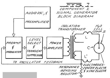
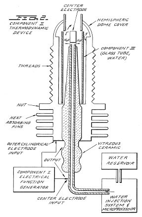
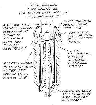
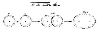
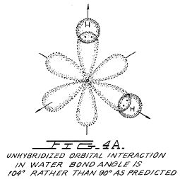
FIG.
4B is an illustration of hybridized and un-hybridized
orbitals;
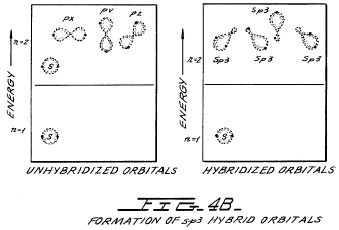
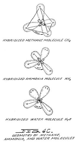

FIG.
6 is an illustration of a ripple square wave;
FIG. 6 A is
an illustration of unipolar pulses;
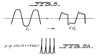
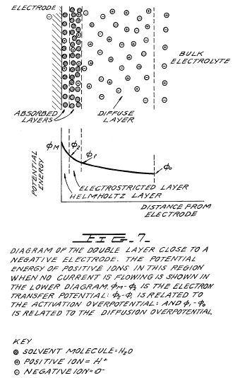
FIG. 8 is an illustration of tetrahedral bonding orbitals;
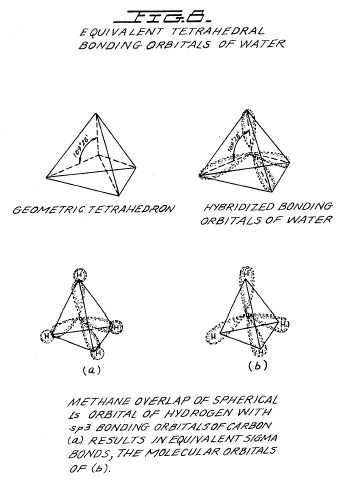
FIG.
9 is an illustration of water molecules;
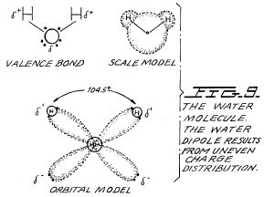
FIG. 10 is an illustration of productive and non-productive collisions of hydrogen with iodine;

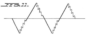
FIG. 12 is an illustration of pearl chain formation;
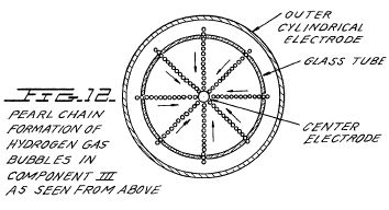
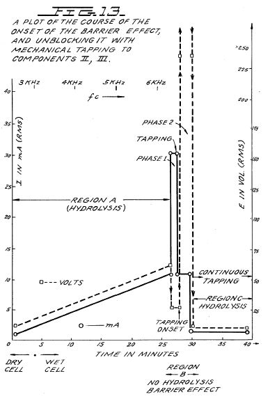
FIG.
13 is a plot of the course of the onset of the barrier effect
and the unblocking of the barrier effect; and
FIGS.
14A, B, and C are energy diagrams for exergonic reactions.

DETAILED DESCRIPTION OF INVENTION
Section 1 --- Apparatus of Invention
The apparatus of the invention consists of three components, the electrical function generator, the thermodynamic device, and the water cell.
COMPONENT I. The Electrical Funtion Generator ~
This device has an output consisting of an audio frequency (range 20 to 200 Hz) amplitude modulation of a carrier wave (range 200 Hz to 100,000 Hz). The impedance of this output signal is continuously being matched to the load which is the second component, the thermodynamic device.
The electrical function generator represents a novel application of circuitry disclosed in my earlier U.S. Pat. Nos. 3,629,521; 3,563,246; and 3,726,762, which are incorporated by reference herein. See FIG. 1 for the block diagram of Component I.
COMPONENT II. The Thermodynamic Device ~
The thermodynamic device is fabricated of metals and ceramic in the geometric form of coaxial cylinder made up of a centered hollow tubular electrode which is surrounded by a larger tubular steel cylinder, said two electrodes comprising the coaxial electrode system which forms the load of the output of the electrical function generator, Component I. Said center hollow tubular electrode carries water, and is separated from the outer cylindrical electrode by a porous ceramic vitreous material. Between the outer surface of the insulating ceramic vitreous material, and the inner surface of the outer cylindrical electrode exists a space to contain the water to be electrolysed. This water cell space comprises the third component (Component III) of the invention. It contains two lengths of tubular pyrex glass, shown in FIGS. 2 and 3. The metal electrode surfaces of the two electrodes which are in contact with the water are coated with a nickel alloy.
The coaxial electrode system is specifically designed in materials and geometry to energize the water molecule to the end that it might be electrolysed. The center electrode is a hollow tube and also serves as a conductor of water to the Component III cell. The center tubular electrode is coated with a nickel alloy, and surrounded with a porous vitreous ceramic and a glass tube with the exception of the tip that faces the second electrode. The outer cylindrical electrode is made of a heat conducting steel alloy with fins on the outside, and coated on the inside with a nickel alloy. The center electrode, and the cylindrical electrode are electrically connected by an arching dome extension of the outer electrode which brings the two electrodes at one point to a critical gap distance which is determined by the known quenching distance for hydrogen. See FIG. 2 for an illustration of Component II.
COMPONENT III. The Water Cell
The water cell is a part of the upper end of Component II, and has been described. An enlarged schematic illustration of the cell is presented in FIG. 3. The Component III consists of the water and glass tubes contained in the geometrical form of the walls of cell in Component II, the thermodynamic device. The elements of a practical device for the practice of the invention will include:
(A) Water reservoir; and salt reservoir; and/or salt
(B) Water injection system with microprocessor or other controls which sense and regulate (in accordance with the parameters set forth hereinafter):
a. carrier frequency
b. current
c. voltage
d. RC
relaxation time constant of water in the cell
e. nuclear
magnetic relaxation constant of water
f.
temperature of hydrogen combustion
g. carrier
wave form
h. RPM of an
internal combustion engine (if used)
i. ignition
control system
j.
temperature of region to be heated;
(C) An electrical ignition system to ignite the evolved hydrogen gas fuel.
The important aspects of Component III are the tubular vitreous material, the geometry of the containing walls of the cell, and the geometrical forms of the water molecules that are contained in the cell. A further important aspect of the invention is the manipulation of the tetrahedral geometry of the water molecule by the novel methods and means which will be more fully described in the succeeding sections of this specification.
The different parts of a molecule are bound together by electrons. One of the electron configurations which can exist is the covalent bond which is achieved by the sharing of electrons. A molecule of hydrogen gas, H2 is the smallest representative unit of covalent bonding, as can be seen in FIG. 4. The molecule of hydrogen gas is formed by the overlap and pairing of 1s orbital electrons. A new molecular orbit is formed in which the shared electron pair orbits both nuclei as shown in FIG. 4. The attraction of the nuclei for the shared electrons holds the atoms together in a covalent bond.
Covalent bonds have direction. The electronic orbitals of an uncombined atom can change shape and direction when that atom becomes part of a molecule. In a molecule in which two or more covalent bonds are present the molecular geometry is dictated by the bond angles about the central atom. The outermost lone pair (non-bonding) electrons profoundly affect the molecular geometry.
The geometry of water illustrates this concept. In the ground state, oxygen has the outer shell configuration
1s2 2s2 2p2x 2p1y 2p1z
In water the 1s electrons from two hydrogens bond with the 2py and 2pz electrons of oxygen. Since p orbitals lie at right angles to each other (see FIG. 4A), a bond angle of 90° might be expected. However, the bond angle is found experimentally to be approximately 104°. Theoretically this is explained by the effect of lone pair electrons on hybridized orbitals.
Combined or hybrid orbitals are formed when the excitement of 2s electrons results in their promotion from the ground state to a state energetically equivalent to the 2p orbitals. The new hybrids are termed sp3 from the combination of one s and three p orbitals (See FIG. 4B). Hybrid sp3 orbitals are directed in space from the center of a regular tetrahedron toward the four corners. If the orbitals are equivalent the bond angle will be 109°28' (See Fig. 15) consistent with the geometry of a tetrahedron. In the case of water two of the orbitals are occupied by non-bonding electrons (See FIG. 4C). There is greater repulsion of these lone pair electrons which orbit only one nucleus, compared to the repulsion of electrons in bonding orbitals which orbit two nuclei. This tends to increase the angle between non-bonding orbitals so that it is greater than 109°, which pushes the bonding orbitals together, reducing the bond angle to 104°. In the case of ammonia, NH3 where there is only one lone pair, the repulsion is not so great and the bond angle is 107°. Carbon forms typical tetrahedral forms and components the simplest being the gas methane, CH4 (See FIGS. 4C and 8). The repulsion of lone pair electrons affects charge distribution and contributes to the polarity of a covalent bond. (See FIG. 16)
As demonstrated in succeeding sections of this patent specification, a significant and novel aspect of this invention is the manipulation, by electronic methods and means, of the energy level of the water molecule, and the transformation of the water molecule into, and out of, the geometrical form of the tetrahedron. This is made possible only by certain subtle dynamic interactions among the Components I, II, and III of the present invention.
Section 2 --- Electrodynamics (Pure Water) ~
The electrodynamics of Components I, II, and III described individually and in interaction during the progress of purewater reaction rate in time. The reactions of saline water will be described in Section 3. It is to be noted that the output of Component I automatically follows the seven stages (hereinafter Stages A-F) of the reaction rate by varying its parameters of resonant carrier frequency, wave form, current voltage and impedance. All the seven states of the reaction herein described are not necessary for the practical operation of the system, but are included in order to explicate the dynamics and novel aspects of the invention. The seven stages are applicable only to the electrolysis of pure water.
STAGE A
Dry Charging of Component II by Component I ~
To make the new system operational, the Component I output electrodes are connected to component II, but no water is placed in the cell of Component III. When Component I output is across the load of Component II we observe the following electrical parameters are observed:
Range of current (I) output with (dry) load:
0 to 25 mA (milliamperes) rms.
Range of voltage (E) output with (dry) load:
0 to 250 Volts (AC) rms.
There is no distortion of the amplitude modulated (AM), or of the sine wave carrier whose center frequency, fc'
Ranges between 59,748 Hz to 66, 221 Hz
with fc average = 62, 985 Hz
The carrier frequency varies with the power output in that fc goes down with an increase in amperes (current). The AM wave form is shown in FIG. 5. It is to be noted here that the electrical function generator, Component I, has an automatic amplitude modulation volume control which cycles the degree of AM from 0% to 100%, and then down from 100% to 0% .congruent. every 3.0 seconds. This cycle rate of 3.0 seconds corresponds to the nuclear spin relaxation time, tau/sec, of the water in Component III. The meaning of this effect will be discussed in greater detail in a later section.
In summary, the principal effects to be noted during Stage A -dry charging of Component II are as follows:
a. Tests the integrity of Component I circuitry.
b. Tests the integrity of the coaxial electrodes, and the vitreous ceramic materials of Component II and Component III.
c. Electrostatic cleaning of electrode and ceramic surfaces.
STAGE B
Initial operation of Component I, Component II, and with Component III containing pure water. There is no significant electrolysis of water during Stage B. However, in Stage B the sine wave output of Component I is shaped to a rippled square wave by the changing RC constant of the water as it is treated;
There is an `Open Circuit` reversible threshold effect that occurs in Component III due to water polarization effects that lead to half wave rectification and the appearance of positive unipolar pulses; and
There are electrode polarization effects in Component II which are a prelude to true electrolysis of water as evidenced by oxygen and hydrogen gas bubble formation.
Appearance of Rippled Square Waves ~
Phase 1: At the end of the Stage A dry charging, the output of Component I is lowered to a typical value of:
I = 1mA. E = 24VAC. fc .congruent.66,234 Hz.
Phase 2: Then water is added to the Component III water cell drop by drop until the top of the center electrode, 1', in FIG. 3 is covered, and when this water just makes contact with the inner surface of the top outer electrode at 2'. As this coupling of the two electrodes by water happens, the following series of events occur:
Phase 3: The fc drops from 66,234 Hz, to a range from 1272 Hz to 1848 Hz. The current and voltage both drop, and begin to pulse in entrainment with the water nuclear spin relaxation constant, tau =3.0 sec. The presence of the nuclear spin relaxation oscillation is proven by a characteristic hysteresis loop on the X-Y axes of an oscillscope.
I = 0 to 0.2mA surging at .tau. cycle
E = 4.3 to 4.8VAC surging at .tau. cycle
The sine wave carrier converts to a rippled square wave pulse which reflects the RC time constant of water, and it is observed that the square wave contains higher order harmonics. See FIG. 6:
With the appearance of the rippled square wave, the threshold of hydrolysis may be detected (just barely) as a vapor precipitation on a cover glass slip placed over the Component III cell and viewed under a low power microscope.
The `Open Circuit` Reversible Threshold Effect ~
Phase 4: A secondary effect of the change in the RC constant of water on the wave form shows up as a full half wave rectification of the carrier wave indicating a high level of polarization of the water molecule in tetrahedral form at the outer electrode.
With the already noted appearance of the rippled square wave, and the signs of faint vapor precipitation which indicate the earliest stage of electrolysis, it is possible to test for the presence of a reversible hydrolysis threshold. This test is carried out by creating an open circuit between Components I and II, i.e., no current flows. This is done by lowering the water level between the two electrodes in the region --- 1' and 2' shown in FIG. 3; or by interrupting the circuit between Component I and II, while the Component I signal generator is on and oscillating.
Immediately, with the creation of an `open circuit` condition, the following effects occur:
(a) The carrier frequency, fc, shifts from Phase 4 valve 1272 Hz to 1848 Hz to 6128 Hz.
(b) The current and voltage drop to zero on the meters which record I and E, but the oscilloscope continues to show the presence of the peak-to-peak (p-p) voltage, and the waveform shows a remarkable effect. The rippled square wave has disappeared, and in its place there appear unipolar (positive) pulses as follows in FIG. 6A.
The unipolar pulse frequency stabilizes to ca. 5000 Hz. The unipolar pulses undergo a 0 to 1.3 volt pulsing amplitude modulation with .tau. at 3.0 seconds.
Thus, there exists a pure open circuit reversible threshold for water electrolysis in which the water molecules are capacitor charging and discharging at their characteristic low frequency RC time constant of 0.0002 seconds. It is to be noted that pure water has a very high dielectric constant which makes such an effect possible. The pulsing amplitude modulation of the voltage is determined by the Hydrogen Nuclear Spin Relaxation constant, where .tau..congruent.3.0 seconds. It is to be noted that the positive pulse spikes are followed by a negative after-potential. These pulse wave forms are identical to the classic nerve action potential spikes found in the nervous system of all living species that have a nervous system. The fact that these unipolar pulses were observed arising in water under the conditions of reversible threshold hydrolysis has a profound significance. These findings illuminate and confirm the Warren McCulloch Theory of water "crystal" dynamics as being the foundation of neural dynamics; and the converse theory of Linus Pauling which holds that water clathrate formation is the mechanism of neural anesthesia.
Phase 5: The effects associated with reversible threshold electrolysis are noted only in passim since they reflect events which are occurring on the electrode surfaces of Component II, the Thermodynamic Device.
A principal effect that occurs in Stage B, Phase 3, in Component II, the thermodynamic device, is that the two electrodes undergo stages of polarization. It has been observed in extensive experiments with different kinds of fluids in the cell of Component II , i.e., distilled water, sea water, tap water, Ringers solution, dilute suspensions of animal and human blood cells, that the inner surface of the outer ring electrode at 3' in FIG. 3 (the electrode that is in contact with the fluid) becomes negatively charged. Referring to FIG. 7, this corresponds to the left hand columnar area marked, Electrode .crclbar..
Electrode Polarization Effects at the Interface Between Components II and III ~
Concurrently with the driver pulsing of Component I at the .tau. constant cycle which leads to electrode polarization effects in Component II, there is an action on Component III which energizes and entrains the water molecule to a higher energy level which shifts the bond angle from 104° to the tetrahedral form with angle 109°28' as shown in FIGS. 8 and 15. This electronic pumping action is most important, and represents a significant part of the novel method of this invention for several reasons. First, the shift to the tetrahedral form of water increases the structural stability of the water molecule, thereby making it more susceptible to breakage at the correct resonant frequency, or frequencies. Second, increasing the polarization of the water molecule makes the lone pair electrons, S- connected with the oxygen molecule more electronegative; and the weakly positive hydrogen atoms, S+ more positive. See FIG. 9 and FIG. 22.
As the outer electrode becomes more electronegative, the center electrode concomitantly becomes more electropositive as will be shown. As the polarity of the water molecule tetrahedron increases, a repulsive force occurs between the two S+ apices of the water tetrahedron and the negatively charged electrode surface within the region of the Helmholtz layer, as shown in FIG. 7. This effect "orients" the water molecule in the field, and is the well-known "orientation factor" of electrochemistry which serves to catalyse the rate of oxygen dissociation from the water molecule, and thereby causes the reaction rate to proceed at the lowest energy levels. See FIG. 10 for an example of how the orientation factor works.
Near the end of Stage B, the conditions are established for the beginning of the next stage, the stage of high efficiency electrolysis of water.
STAGE C
Generation of the complex wave form frequencies from Component I to match the complex wave form resonant frequencies of the energized and highly polarized water molecule in tetrahedral form with angles, 109°28' are carried out in Stage C.
In the operation of the invention active bubble electrolysis of water is initiated following Stage B, phase 3 by setting (automatically) the output of Component I to:
I = 1mA., E = 22VAC-rms,
causing the rippled square wave pulses to disappear with the appearance of a rippled sawtooth wave. The basic frequency of the carrier now becomes, fc = 3980 Hz.
The wave form now automatically shifts to a form found to be the prime characteristic necessary for optimum efficiency in the electrolysis of water and illustrated in FIG. 11. In the wave form of FIG. 11, the fundamental carrier frequency, fc = 3980 Hz., and a harmonic modulation of the carrier is as follows:
1st Order Harmonic Modulation (OHM) = 7960 Hz.
2nd Order Harmonic Modulation (II OHM) = 15,920 Hz.
3rd Order Harmonic Modulation (III OHM) = 31,840 Hz.
4th Order Harmonic Modulation (IV OHM) = 63,690 Hz.
What is believed to be happening in this IV OHM effect is that each of the four apices of the tetrahedron water molecule is resonant to one of the four harmonics observed. It is believed that the combination of negative repulsive forces at the outer electrode with the resonant frequencies just described work together to shatter the water molecule into its component hydrogen and oxygen atoms (as gases). This deduction is based on the following observations of the process through a low power microscope. The hydrogen bubbles were seen to originate at the electrode rim, 4', of FIG. 3. The bubbles then moved in a very orderly `pearl chain` formation centripetally (like the spokes of a wheel) toward the center electrode, 1' of FIG. 3. FIG. 12 shows a top view of this effect.
Thereafter, upon lowering the output of Component I, the threshold for electrolysis of water as evidenced by vapor deposition of water droplets on a glass cover plate over the cell of Component III, is:
with all other conditions and waveforms as described under Stage C, supra. Occasionally, this threshold can be lowered to:
![]()
This Stage C vapor hydrolysis threshold effect cannot be directly observed as taking place in the fluid because no bubbles are formed --- only invisible gas molecules which become visible when they strike a glass plate and combine into water molecules and form droplets which appear as vapor.
STAGE D
Production of hydrogen and oxygen gas at an efficient rate of water electrolysis is slowed in Stage D when a barrier potential is formed, which barrier blocks electrolysis, irrespective of the amount of power applied to Components II and III.
A typical experiment will illustrate the problems of barrier potential formation. Components I, II, and III are set to operate with the following parameters:

This input to Component III yields, by electrolysis of water, approximately 0.1 cm3 of hydrogen gas per minute at one atmosphere and 289° K. It is observed that as a function of time the fc crept up from 2978 Hz to 6474 Hz over 27 minutes. The current and the voltage also rose with time. At the 27th minute a barrier effect blocked the electrolysis of water, and one can best appreciate the cycle of events by reference to FIG. 13.
STAGE E
The Anatomy of the Barrier Effect
Region A: Shows active and efficient hydrolysis
Region B: The barrier region effect can be initiated with taps of the finger, or it can spontaneously occur as a function of time.
Phase a: The current rose from 1 mA to 30 mA. The voltage fell from 22 volts to 2.5 V.
Phase b: If component II is tapped mechanically during Phase a supra --- it can be reversed as follows: The current dropped from 30 Ma to 10 Ma. The voltage shot up from 5 volts to over 250 volts (off scale).
Throughout Phase a and Phase b, all hydrolysis has ceased. It was observed under the microscope that the inner surface of the outer electrode was thickly covered with hydrogen gas bubbles. It was reasoned that the hydrogen gas bubbles had become trapped in the electrostricted layer, because the water molecule tetrahedrons had flipped so that the S+ hydrogen apices had entered the Helmholtz layer and were absorbed to the electronegative charge of the electrode. This left the S- lone pair apices facing the electrostricted layer. This process bound the newly forming H.sup.+ ions which blocked the reaction
H+ + H+ + 2e ==> H2 (gas)
STAGE F
Region C: It was found that the barrier effect could be unblocked by some relatively simple procedures:
(a) Reversing the output electrodes from Component I to Component II, and/or:
(b) Mechanically tapping the Component III cell at a frequency T/2 = 1.5 seconds per tap.
These effects are shown in FIG. 12 and induce the drop in barrier potential from:

Upon unblocking of the barrier effect, electrolysis of water resumed with renewed bubble formation of hydrogen gas.
The barrier potential problem has been solved for practical application by lowering the high dielectric constant of pure water, by adding salts (NaCl, KOH, etc.) to the pure water thereby increasing its conductivity characteristics. For optimum efficiency the salt concentration need not exceed that of sea water (0.9% salinity) in Section 3, "Thermodynamics of the Invention", it is to be understood that all water solutions described are not "pure" water as in Section B, but refer only to salinized water.
Section 3 --- The Thermodynamics of the Invention (Saline Water) ~
Introduction (water, hereinafter refers to salinized water) ~
The thermodynamic considerations in the normal operations of Components I, II, and III in producing hydrogen as fuel, and oxygen as oxidant during the electrolysis of water, and the combustion of the hydrogen fuel to do work in various heat engines is discussed in this section.
In chemical reactions the participating atoms form new bonds resulting in compounds with different electronic configurations. Chemical reactions which release energy are said to be exergonic and result in products whose chemical bonds have a lower energy content than the reactants. The energy released most frequently appears as heat. Energy, like matter, can neither be created nor destroyed according to conservation law. The energy released in a chemical reaction plus the lower energy state of the products is equal to the original energy content of the reactants. The burning of hydrogen occurs rather violently to produce water as follows:
2H2 + O2 ===> 2H2O - .DELTA.H 68.315 Kcal/mol (this is the enthalpy, or heat of combustion at constant pressure)
(18 gms) = 1 mol)
The chemical bonds of the water molecules have a lower energy content than the hydrogen and oxygen gases which serve at the reactants. Low energy molecules are characterized by their ability. High energy molecules are inherently unstable. These relations are summarized in the two graphs of FIG. 14. It is to be noted that FIG. 14 (b) shows the endergonic reaction aspect of the invention when water is decomposed by electrolysis into hydrogen and oxygen. FIG. 14 (a) shows the reaction when the hydrogen and oxygen gases combine, liberate energy, and re-form into water. Note that there is a difference in the potential energy of the two reactions. FIG. 14 (c) shows that there are two components to this potential energy. The net energy released, or the energy that yields net work is labelled in the diagram as Net Energy released, and is more properly called the free energy change denoted by the Gibbs function, -.DELTA.G. The energy which must be supplied for a reaction to achieve (burning) spontaneity is called the activation energy. The sum of the two is the total energy released. A first thermodynamic subtlety of the thermodynamic device of the invention is noted in Angus McDougall's Fuel Cells, Energy Alternative Series, The MacMillan Press Ltd., London, 1976, page 15 it is stated:
"The Gibbs function is defined in terms of the enthalpy H, and the entropy S of the system:
G = H-T S (where .tau. is the thermodynamic temperature)
A particularly important result is that for an electrochemical cell working reversibly at constant temperature and pressure, the electrical work done is the net work and hence,
.DELTA.G = -we
For this to be a reversible process, it is necessary for the cell to be on `open circuit`, that is, no current flows and the potential difference across the electrodes is the EMF, E. Thus,
.DELTA.G = -zFE
(where F is the Faraday constant --- the product of the Avogadro Constant + NA = 6.022045 x 10²³ mole-1, and the charge on the electron, e = 1.602 189 x 10-19 C --- both in SI units; and z is the number of electrons transported.) when the cell reaction proceeds from left to right."
It is to be noted that the activation energy is directly related to the controlling reaction rate process, and thus is related to the Gibbs free energy changes.
The other thermodynamic subtlety is described by S. S. Penner in his work: Penner, S. S. and L. Icerman, Energy, Vol, II, Non-Nuclear Energy Technologies. Addison-Wesley Publishing Company, Inc. Revised Edition, 1977. Reading, Mass. Page 140 ff.
"It should be possible to improve the efficiency achieved in practical electrolysis to about 100% because, under optimal operating conditions, the theoretically-attainable energy conversion by electrolysis is about 120% of the electrical energy input. The physical basis for this last statement will now be considered.
"A useful definition for energy efficiency in electrolysis is the following: the energy efficiency is the ratio of the energy released from the electrolysis products formed (when they are subsequently used) to the energy required to effect electrolysis. The energy released by the process
H2 (gas) + (1/2)O2 (gas) ===> H2O (liquid)
under standard conditions (standard conditions in this example are: (1) atmospheric pressure = 760 mm Hg and (2) temperature = 298.16° K. = 25° C. = 77° F.) is 68.315 Kcal and is numerically equal to the enthalph change (.DELTA.H) for the indicated process. On the other hand, the minimum energy (or useful work input) required at constant temperature and pressure for electrolysis equals the Gibbs free energy change (.DELTA.G). There is a basic relation derivable from the first and second laws of thermodynamics for isothermal changes, which shows that
.DELTA.G = .DELTA.H - T.DELTA.S
where .DELTA.S represents the entropy change for the chemical reaction. The Gibbs free energy change (.DELTA.G) is also related to the voltage (E) required to implement electrolysis by Faraday's equation, viz.
E = (.DELTA.G/23.06n) volts
where .DELTA.G is in Kcal/mol and n is the number of electrons (or equivalents) per mol of water electrolyzed and has the numerical value 2.
"At atmospheric pressure and 300° K., .DELTA.H = 68.315 Kcal/mol of H2O (i) and .DELTA.G = 56.62 Kcal/mole of H2O (i) for the electrolysis of liquid water. Hence, the energy efficiency of electrolysis at 300° K. is about 120%."
![]()
"(When) H2 (gas) and O2 (gas) are generated by electrolysis, the electrolysis cell must absorb heat from the surroundings, in order to remain at constant temperature. It is this ability to produce gaseous electrolysis products with heat absorption from the surroundings that is ultimately responsible for energy-conversion efficiencies during electrolysis greater than unity."
Using the criteria of these two authorities, it is possible to make a rough calculation of the efficiency of the present invention.
Section 4 --- Thermodynamic Efficiency of the Invention ~
Efficiency is deduced on the grounds of scientific accounting principles which are based on accurate measurements of total energy input to a system (debit), and accurate measurements of total energy (or work) obtained out of the system (credit). In principle, this is followed by drawing up a balance sheet of energy debits and credits, and expressing them as an efficiency ration, .eta..
![]()
The energy output of Component I is an alternating current looking into a highly non-linear load, i.e., the water solution. This alternating current generator (Component I) is so designed that at peak load it is in resonance (Components I, II, III), and the vector diagrams show that the capacitive reactance, and the inductive reactance are almost exactly 180° out of phase, so that the net power output is reactive, and the dissipative power is very small. This design insures minimum power losses across the entire output system. In the experiments which are now to be described the entire emphasis was placed on achieving the maximum gas yield (credit) in exchange for the minimum applied energy (debit).
The most precise way to measure the applied energy to Components II and III is to measure the Power, P, in Watts, W. This was done by precision measurements of the volts across Component II as root mean square (rms) volts; and the current flowing in the system as rms amperes. Precisely calibrated instruments were used to take these two measurements. A typical set of experiments (using water in the form of 0.9% saline solution = 0.1540 molar concentration) to obtain high efficiency hydrolysis gave the following results:
rms Current = I = 25 mA to 38 mA (0.025 A to 0.038 A)
rms Volts = E = 4 Volts to 2.6 Volts
The resultant ratio between current and voltage is dependent on many factors, such as the gap distance between the center and ring electrodes, dielectric properties of the water, conductivity properties of the water, equilibrium states, isothermal conditions, materials used, and even the presence of clathrates. The above current and voltage values reflect the net effect of various combinations of such parameters. The product of rms current, and rms volts is a measure of the power, P in watts:
P = I x E = 25 mA.times.4.0 volts = 100 mW (0.1 W)
P = I x E = 38 mA.times.2.6 volts = 98.8 mW (0.0988 W)
At these power levels (with load), the resonant frequency of the system is 600 Hz (.+-.5 Hz) as measured on a precision frequency counter. The wave form was monitored for harmonic content on an oscilloscope, and the nuclear magnetic relaxation cycle was monitored on an X-Y plotting oscilloscope in order to maintain the proper hysteresis loop figure. All experiments were run so that the power in Watts, applied through Components I, II, and III ranged between 98.8 mW to 100 mW.
Since, by the International System of Units --- 1971 (SI), One-Watt-second (Ws) is exactly equal to One Joule (J), the measurements of efficiency used these two yardsticks (1 Ws=1 J) for the debit side of the measurement.
The energy output of the system is, of course, the two gases, hydrogen (H2) and oxygen (1/2O2), and this credit side was measured in two laboratories, on two kinds of calibrated instruments, namely, a Gas Chromatography Machine, and, a Mass Spectrometer Machine.
The volume of gases, H2 and (1/2)O2, was measured as produced under standard conditions of temperature and pressure in unit time, i.e., in cubic centimeters per minute (cc/min), as well as the possibly contaminating gases, such as air oxygen, nitrogen and argon; carbon monoxide, carbon dioxide, water vapor, etc.
The electrical, and gas, measurements were reduced to the common denominator of Joules of energy so that the efficiency accounting could all be handled in common units. The averaged results from many experiments follow. The Standard Error between different samples, machines, and locations is .+-.10%, and only the mean was used for all the following calculations.
Section 5 --- Endergonic Decomposition of Liquid Water ~
Thermodynamic efficiency for the endergonic decomposition of liquid water (salinized) to gases under standard atmosphere (754 to 750 m.m. Hg), and standard isothermal conditions @ 25° C. = 77° F. = 298.16° K., according to the following reaction:
H2O(1) ===> H2 (g) + (1/2)O2 (g) + .DELTA.G 56.620 KCal/mole
As already described, .DELTA.G is the Gibbs function (FIG. 14b). A conversion of Kcal to the common units, Joules, by the formula, One Calorie = 4.1868 Joules was made.
.DELTA.G = 56.620 Kcal x 4.1868 J = 236,954 J/mol of H2O (1) where, 1 mole is 18 gms.
.DELTA.G = the free energy required to yield an equivalent amount of energy from H.sub.2 O in the form of the gases, H2 and (1/2)O2.
To simplify the calculations, the energy required to produce 1.0 cc of H2O as the gases, H2 and (1/2)O2 was determined. There are (under standard conditions) 22,400 cc = V, of gas in one mole of H2O. Therefore,
![]()
The electrical energy required to liberate 1.0 cc of the H2O gases (where H2 = 0.666 parts, and (1/2)O2 = 0.333 parts, by volume) from liquid water is then determined. Since P = 1 Ws = 1 Joule, and V=1.0 cc of gas = 10.5783 Joules, then,
![]()
Since the experiments were run at 100 mW (0.1 W) applied to the water sample in Component II, III, for 30 minutes, the ideal (100% efficient) gas production at this total applied power level was calculated.
0.1 Ws x 60 sec x 30 min = 180.00 Joules (for 30 min)
The total gas production at Ideal 100% efficiency is,
180.00 J / 10.5783 J/cc = 17.01 cc H2O (g)
The amount of hydrogen present in the 17.01 cc H2O (g) was then calculated.
17.01 cc H2O (gas) x 0.666 H2 (g) = 11.329 cc H2 (g)
17.01 cc H2O (g) x 0.333 (1/2)O2 (g) = 5.681 cc (1/2)O2 (g)
Against
this ideal standard of efficiency of expected gas production,
the actual amount of gas produced was measured under: (1)
standard conditions as defined above (2) 0.1 Ws power applied
over 30 minutes. In the experiments, the mean amount of H2
and (1/2)O2 produced, as measured on precision
calibrated GC, and MS machines in two different laboratories,
where the S.E. is +-10%, was,
______________________________________
Measured Mean = 10.80 cc H2
(g)
Measured Mean = 5.40 cc
(1/2) O2 (g)
Total Mean =
16.20 cc H2O(g)
______________________________________
The ratio, .eta., between the ideal yield, and measured yield,
![]()
Section 6 --- Energy Release ~
The total energy release (as heat, or electricity) from an exergonic reaction of the gases, H2 and O2, is given by,
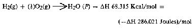
It is possible (Penner, Op. Cit., p. 128) to get a total heat release, or total conversion to electricity in a fuel cell, in the above reaction when the reactants are initially near room temperature (298.16° K.), and the reactant product (H2O) is finally returned to room temperature. With this authoritative opinion in mind, it is desirable to determine the amount of energy released (ideal) from the exergonic experiment. The total energy of 1.0 cc of H2O (1), as above is:
![]()
for H2 = 12.7687 x 0.666 = 8.509 J/0.66 cc H2 for O2 = 12.7687 x 0.333 = 4.259 J/0.33 cc (1/2)O2
The energy produced from the gases produced in the experiments in an exergonic reaction was,
16.20 cc H2O (g) x 12.7687 J/cc H2O = 206,8544 J.
The overall energy transaction can be written as,

In practical bookkeeping terms the balance of debits and credits, n = (-.DELTA.H) - (+.DELTA.G), so, n = 206.8544 J - 180.0 = + 26.8544 J (surplus).
Since, in the invention, the gas is produced where and when needed, there is no additional cost accounting for liquifaction, storage, or transportation of the hydrogen fuel, and the oxygen oxidant. Therefore, the practical efficiency, is
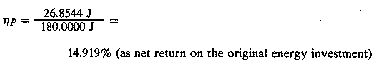
In practical applications, the energy output (exergonic) of the Component II System can be parsed between the electrical energy required to power the Component I System, as an isothermal closed loop; while the surplus of approximately 15% can be shunted to an engine (heat, electrical, battery, etc.) that has a work load. Although this energy cost accounting represents an ideal model, it is believed that there is enough return (app. 15%) on the capital energy investment to yield a net energy profit that can be used to do useful work.
Conclusion ~
From
the foregoing disclosure it will be appreciated that the
achievement of efficient water splitting through the
application of complex electrical waveforms to energized water
molecules, i.e. tetrahedral molecules having bonding angles of
109°28', in the special apparatus described and illustrated,
will provide ample and economical production of hydrogen gas
and oxygen gas from readily available sources of water. It is
to be understood, that the specific forms of the invention
disclosed and discussed herein are intended to be
representative and by way of illustrative example only, since
various changes may be made therein without departing from the
clear and specific teachings of the disclosure. Accordingly,
reference should be made to the following appended claims in
determining the full scope of the method and apparatus of the
present invention.