Pyramid
Energy Patents
CN101703442
Pyramid type magnetic field effect health-promoting and disease-curing functional bed


The invention relates to a pyramid type magnetic field effect health-promoting and disease-curing functional bed, aiming to satisfy the demand that people increasingly pay attention to the quality of life, do not satisfy the current life expectancy and seek good health and a long life. A group of terrestrial magnetism energy concentrators are arranged in an existing bed body; magnets which are connected together through magnet-wire printed circuit boards are distributed on the cover board of a box body below the mattress according to the human body shape and acupuncture points; the bed body is arranged in a pyramid type magnetic field effect device; the device is a tower-shape frame with four equicrural triangle-shaped side faces which are made from four metal sections, transparent bodies are arranged in the tower-shape frame to form a functional cover, a spherical magnetic receiver and a magnetic energy releaser are arranged on the top of the cover; and an open inlet is arranged on the side of the functional cover. The characteristics and beneficial effect of the functional bed are as follows: by using the geometric energy field, geomagnetic field, astrology and star gravitational field theories of the Taiji pyramid building, the energy can be concentrated and act on the human body so as to have function of curing human diseases; and a plurality of clinical tests show that the functional bed has unique effect for curing various difficult and complicated cases.
KR20100005740
GI ENERGY SEX DEVICE

PURPOSE: A pyramid energy sex apparatus is provided, which makes penis erected in a few minutes using energy of the pyramid. CONSTITUTION: A pyramid energy sex apparatus comprises a pyramid; a copper wire connected to the bottom side of the pyramid; a first capacitor connected to the bottom of the pyramid in the plus direction; a second capacitor in which the plus direction is connected to the frequency tuned part; an inductor which is parallel-connected to the capacitor and performs frequency tuning; an amplifier amplifying the frequency tuned energy; and a coil which is parallel-connected to the amplifier, generates sex wave, and is conversely wound counterclockwise.
KR20100005739
GI ENERGY SLEEPING DEVICE

PURPOSE: An energy sleeping apparatus is provided, which makes a user sleep in a few minutes using energy of pyramid power. CONSTITUTION: An energy sleeping apparatus comprises a pyramid; a copper wire connected to the bottom side of the pyramid; a first capacitor connected to the bottom of the pyramid in the plus direction; a second capacitor; an inductor which is parallel-connected to the capacitor and performs frequency tuning; an amplifier amplifying the frequency tuned energy; and a coil which is parallel-connected to the amplifier and is conversely wound counterclockwise.
UA32342
METHOD FOR ENERGY-AND-INFORMATION TREATMENT OF FLUID
A method for energy-and-information treatment of the fluid comprises storing the fluid inside the container with the cover designed as the regular rectangular pyramid and providing the exposure of the fluid inside to the fields of the regular rectangular shape.
UA32341
DEVICE FOR ENERGY-AND-INFORMATION TREATMENT OF FLUID OR FLOWABLE MATERIAL


Device for energy-and-information treatment of the fluid or the flowable material contains the container with the cover in the shape of the regular rectangular pyramid for storing the material and providing energy-and-information treatment.
UA29223
TANK FOR IMPROVEMENT OF WATER ENERGY PROPERTIES
A tank for the improvement of water energy properties corresponds a housing made of dielectric material in the form of a nine-hedral regular truncated pyramid with an open upper base.
UA28144
FACET OF AN ENERGY-EMITTING PYRAMID "KHVYLIA"

It is proposed the design of a facet of an energy pyramid with increased intensity of emitted energy.
UA28143
FACET OF AN ENERGY-EMITTING PYRAMID "STRILA"

It is proposed the design of a facet of an energy pyramid with increased intensity of emitted energy.
UA28813
ENERGY FACE OF A PYRAMID "KATAMARAN"

The proposed face of an energy pyramid contains parallel horizontal lines. Between the lines, a strip with metallic coating is arranged. The strip forms a projection that is arranged in parallel to the edge of the pyramid face.
RS943
PYRAMID ENERGY UNIT


Abstract not available for RS943
UA27840
RESERVOIR FOR IMPROVING ENERGETIC PROPERTIES OF WATER USED FOR PLANT IRRIGATION
A reservoir for improving the energetic properties of water used for plant irrigation is designed as nonahedron with the walls made of dielectric material. The reservoir represents the regular truncated pyramid with the open upper base. The ratio between the diameters of the circumcircles of the upper and lower bases is 0.19-0.22:1. The ratio between the height of the reservoir and the diameters of the circumcircle of the lower base is 0.7-0.9:1. The angle between facet of the nonahedron and its base is 61 DEGREE -67 DEGREE . The device is used for improving the energetic properties of the water used for plant irrigation due to the energy of the pyramidal construction.
WO2008094038
DEVICE FOR GENERATING AN ENERGY FIELD AND A SYSTEM OF SUCH A DEVICE AND ONE OR MORE TREATMENT INSTRUMENTS
The present invention relates to a device (1) for generating an energy field, comprising a first housing (10) in which one or more pyramid-shaped elements of electrically conductive material and one or more coils are arranged. The housing is provided with a connection for a voltage source (20) to the pyramid-shaped elements and/or the one or more coils. The housing is further provided with means (30, 110, 120, 130, 140, 150) for transferring the energy field to a living organism, for instance a human being. The invention also relates to a system (100) of a device (1) according to the invention and one or more treatment instruments (110, 120, 130, 140, 150) connected to the device, wherein each of the treatment instruments is adapted to transfer the energy field onto a living organism, for instance a human being.
AU2007200359
Pyramid energy devices
Invention
The energy concentrating effects of pyramids has long been known.
According to the currently accepted supposition the common resultant of cosmic space, terrestrial space, electric, magnetic, corpuscular and other, thus far unknown particles and energies could be responsible for phenomena taking place in pyramid shaped spaces.
The closest, to the offered invention is the device in a general concept, considering the principle of effective concentration and generation of pyramid energy and principle of effective distribution of this energy by spiral (INSTRUMENT AND PROCEDURE FOR THE USE OF PYRAMID ENERGY, application AU2002358920 (Publication date is 20 04-07-22) (WO2004058339 Application number: AU20020358920 20021231; Priority number WO2002HU00179 20021231, IPCI-7: A61M21/00, A61N1/16, A61N1/00).
In this general concept a separate device from system of the same devices in the specified application represents a figure of the pyramidal form with the flat bases. The description of separate devices of the pyramidal form, from the system does not contain data about concrete specific constructive attribute of realization of the device. Specification of the prototype is the spiral system of pyramidal devices, and not a separate device, and influence of system on bioobjects through saturation of water contained in them by pyramid energy.
The substance containing water may ideally be the human body, tea, fruit, vegetables, juices etc. Substance containing water thus treated may be used for treating human and animal sicknesses. However, influence of pyramid energy on different objects can be not only curing but also intimidating.
A method of protection against rodents and insects with its application Technical field of the invention The invention relates to the field of devices of generated concentration of energy which can be used for correction of energy states of bioobjects in various industries, agriculture or domestic situations, in particular, the protection of premises (shops, warehouses, eating establishments) from rodents (rats, mice) and insects (ants, termites, cockroaches, flies) by means of detracting and/or destroying them.
Summary
Task of the invention is the expansion of functions of the device for generated concentration of pyramid energy by effective energy influence on different objects and including the application for effective protection of premises and their contents against destruction by rodents and insects.
00 To fulfill this task, the essential attribute of the offered device is the usage of r, rigidly connected pieces of electric wire for creation of the symmetric pyramidal form of the device, arrangement of the Reich's energy accumulator executed in the form of sphere inside the pyramidal form on the central vertical axis and arrangement of sphere of amplification and optimization of energy radiation on top of the pyramidal form connected with Reich's energy accumulator by electric conductor.
Variants (embodiments) of the pyramidal form the device can be executed:
c,1 In the form of a correct tetrahedral pyramid enclosed inside of an additional correct tetrahedral pyramid with the common plane of the bases and with the common top of both pyramids, and the attitude of the areas of the bases of external and internal pyramids make 2:1, and the center of sphere of Reich's accumulator is located on 1/3 height of pyramids from their bases;
The figure of the pyramidal form is formed by a ring of wire, forming the base, three pieces of wire have two parts, the first part represents the spatial spirals located on a surface of part of ellipsoid with a direction of coils counter-clockwise, and the second part represents flat spirals inside of the ring base, converging in its center, and points of interface of spatial and flat parts are located on the base ring on angular distance 120 degrees from each other, and angles of twisting of flat parts of spirals and the angles of twisting of projections of spatial parts on a plane of the base are equal to each other and made from 0.5 up to 1.5 angular turnovers around vertical axis, the center of the sphere of Reich's accumulator is located on half of the height from the top to a plane of the base.
By such embodiments of the device inventors made purposeful influences on objects: improving energy fields of people and foodstuff while dispersing small rodents and insects.
For realization of the method of protection against rodents and insects, the devices are kept on the protected premises whenever possible and at a convenient distance without interruption to the user. The necessary quantity of the devices depends on the size of the protected area with an approximate ratio of overall dimension of the base of the device of 10 cm for 3.5 m length of floor of an area.
Brief description of the drawings
FIG. 1. Shows a first embodiment of the device.
FIG. 2. Shows a second embodiment of the device.


Detailed description of the preferred embodiments:
00 Main principle of application of the offered devices is the definition of influence of a level of energy initially existing in object and demanded effect of a so-called resource level necessary for achievement. Further means of the t devices of the necessary size and quantity, the demanded resource level of energy is created for the decision of tasks in view.
ri Effective generation of pyramid energy is impossible without its effective concentration in the device. Reich's accumulator is used for amplification Seffect of concentrated energy, and the sphere on top of the pyramidal form of N the device is used for optimizing the energy radiation. It is known, that Reich's accumulator acts in a role of the receiver-condenser of energy from the outside that through the sphere on top of the pyramidal form device forms the concentrated field around the device. Reich made metal and wood boxes cosmic orgone energy accumulators (in more common case accumulators with metal and dielectric layers). So in our case, Reich's accumulator represents multilayered structure of dielectric and metal layers, with an external dielectric layer (for example, a dielectric polymeric film) and an internal core from metal (a steel ball). Reliability of wide energy opportunities of Reich's accumulator proves to be true documentary, and its action continuum. The sphere of amplification and optimization of radiation of energy represents a ball from the metal foil, which has been wound up around the top. The effect of optimization of radiation of energy is represented in more harmonious tranquility radiated energy above and along the surface of the device.
The first embodiment of the device has the traditional form of correct pyramids with an inclusion of a smaller pyramid inside the larger one also for amplification effect of concentration and generation of pyramid energy. The second embodiment of the device with the smoothed pyramidal form of ellipsoid realizes the spiral principle considering close interrelation of Space and Time in existential thermographicaly objectificated, thus in additional influence on a person there is a strengthened component of adjustment (objective parameters of state), time rhythms of the person, in particular, his sleep as essential part of a daily regime.
Practice has shown that small rodents and insects do not remain in the invaded areas due to correcting surrounding space energy concentrated and generated by the offered devices, as the size and capacity of their own energy fields of rodents (rats, mice) and insects are much less than sizes of area and capacity of the energy generated by the offered device. For example, rats have field size of cm (mice and insects as essences of the smaller size, than rats, have the sizes of their fields naturally also much less) in comparison with approximately 25 m of the size of area of concentration of energy by the device with length of sides of the bases 70 cm.
O The method has many obvious advantages, especially important in the food 0processing industry: ecologically pure and safe, without application of harmful pesticides and radiations harmful to people; rodents and insects fail to build immunity to the influence of the devices; the task of installation of the offered systems in remote places do not require any technological process or electrical 00 installation.
Proofs of efficiency of application of the offered prototype devices and the method are given in the following examples, which proved to be of positive benefit to the user:
a) After visiting a veterinary clinic with a "sick" gang gang, the diagnosis revealed an incurable virus found quite common amongst these birds.
Had no appetite, loss of feathers, beak breakage and very poor Scondition. After introducing the pyramid devices for two or three months, the bird's improvement was very noticeable by his condition, his "hungry" appetite, growth of feathers and mended beak.
b) A young couple in the midst of a marital break up mended their relationship with the introduction of the spiral device. It provided a much more relaxing atmosphere in the home, taking away the tension between them. They also noticed the disappearance of ants after several days that had been present earlier. All the above was achieved within one or two months.
c) The pyramid device was introduced to a food preparation and take away establishment. The proprietor was an experienced businessman and well established but disharmony within the establishment was evident. Within two or three months of the device being installed, the proprietor became much more mellow and staff increased productivity without any tension. Business takings increased, insects disappeared followed by a very pleasing event that never experienced by the proprietor before, and he received a cheque in the mail.
d) A friend installed the device due to irritability and "nothing going right". Within two or three months of the installation, he bought his first home for a good price, he sleeps better, his plants are growing very healthy, all visiting relatives staying overnight remark on their restful sleep, better fuel economy running his car and no insects.
e) A relative experiencing an on going health problem with his heart, stomach and poor circulation in the left leg installed a pyramid device to help with sleep. After several months, his cardiologist commented on his heart function being better than usual after a regular check up, although nothing was mentioned about the device. The left leg is functioning and looks better while the stomach is gradually improving.
Food stores noticeably longer and better, very evident by the disappearance of flies and ants or other insects.
EA200602270
METHOD FOR COMBATING RODENTS, COCKROACHES AND DEVICE THEREFOR
Also published as: EA008673

The invention relates to means of affecting upon rodents (rats, mice) and cockroaches for protection premises (shops, warehouses, eating establishments, rooms, etc) against them by scaring and/or killing. For better efficiency there proposed concentrated energy of electromagnetic field naturally induced in current-conducting material of formed wires. The inventive method and the device are aimed at providing an appropriate effectiveness of protection of food products and consumer goods stored in premises of any sizes against rodents and cockroaches. The method includes using electromagnetic field naturally induced in current-conducting material of formed wires cardinal oriented.; The method is characterized in that tetrahedral pyramids are preassembled from the formed wires, each of the pyramid has an additional tetrahedral pyramid of smaller size enclosed thereinto, both pyramids have common a base plane and a common pyramid vertex. A ball-shaped power amplifier is arranged in the pyramid vertex and coupled with a Reich storage battery made as a sphere and spaced about 1/3 of the pyramid height from the pyramid base to the center of the sphere of the Reich storage battery. The bases areas of the outer and inner pyramids are rated to about 2:1. The pyramids are cardinal oriented by their faces. A number of pyramids required for premises protection is calculated and constitutes 10 cm of the length of the outer pyramid base side per about 3.5 m of the premises floor length. The method is accompanied by a device therefore.
JP2008068056
ENERGY PATCH FOR REGULATING VITAL ENERGY AND BLOOD OF HUMAN BODY
Also published as: WO2008032890 (A1) US2008081940


PROBLEM TO BE SOLVED: To provide an energy patch for regulating vital energy and blood, which is equipped with the concept of "Hosha" (a Chinese medical treatment for redeeming a sick person's physical strength and vigor and for expelling diseases from the human body) so that the energy patch can be applied to the meridian and meridian point regions of the human body and simply used. ; SOLUTION: This energy patch comprises: a rubber alloy magnet which is formed in such a planar shape as to have the characteristics of a permanent magnet equipped with a north pole and a south pole, which keeps a pointed corner directed downward, and at least a pointed corner upward; a color coating member which enables color printing to be applied to either of the sides of the rubber alloy magnet; and an adhesive member which enables the rubber alloy magnet to adhere to the skin of the human body. The energy patch can be applied to the understanding of the nature of the disease, the measurement and regulation of the excess and deficiency of the vital energy and blood, the prevention of the disease, etc.; and the pyramid effect of the shape of the energy patch brings about the effect of activating biological energy and treating the diseases. In the application of the energy patch, since the energy patch adheres to the specific region of the human body in consideration of the directional essence and color essence of life of the human body, the energy patch can bring about the effect of acupuncture concurrently with a magnetic treatment, so as to exert the effect of promoting the health of the human body by regulating the vital energy and blood.
KR20070122080
APPARATUS FOR GENERATING PYRAMID ENERGY USING PYRAMID STRUCTURE


An energy generating device using a pyramid structure is provided to amplify pyramid energy of the pyramid structure by changing a magnetic field by applying high frequency to the pyramid structure. An energy generating device(10) generating pyramid energy in a pyramid structure(100) is composed of the pyramid energy generating pyramid structure; a case(200) containing the pyramid structure; a high frequency generating and heating substrate(400) installed at the inner bottom of the case and operated electrically or magnetically by receiving electricity from an external power source, in order to generate a high frequency signal and heat and amplify pyramid energy generated from the pyramid structure; and an object holder(500) formed at the outer upper part of the case to place an object and absorb pyramid energy generated from the pyramid structure stored in the case.
US2010031842
SPACE ENERGY IMPLOSION UNIT AND AN ENERGY AMPLIFICATION GENERATOR USING THE SAME
Also published as: WO2008041812 (A1) JP2010521415 (A) EP2086637 (A1) EP2086637
Abstract
Provided are a space energy implosion unit and an energy amplification generator using the same. The space energy implosion unit includes: a planar structure 1 having a regular pentagonal shape; a cubic structure 2 which is installed to be separated from an upper portion of the planar structure 1 and has a regular pentagonal pyramid shape; and a separation structure 3 which separates the planar structure 1 and the cubic structure 2 from each other and has a smaller area than areas of the planar structure 1 and the cubic structure 2. The energy amplification generator includes: a first geometrical structure in which vertices of each of five or seven pieces of planar structures 1 having a regular pentagonal shape contact one another; a second geometrical structure which is separated from an upper portion of the first geometrical structure and in which vertices of each of five or seven cubic structures 2 having a regular pentagonal pyramid shape contact one another; and a plurality of separation structures 3 which separate the first geometrical structure and the second geometrical structure from each other, are installed between the planar structure 1 and the cubic structure 2 and have a smaller area than areas of the planar structure 1 and the cubic structure 2.
TECHNICAL FIELD
[0001] The present invention relates to a space energy implosion unit which implodes a little energy that is full in the universe to be directly and indirectly used, and an energy amplification generator using the same.
BACKGROUND ART
[0002] Newton's Mechanics in which the nature of materials is defined as particles dominate classical scientific circles. However, as quantum mechanics and relativity theory are established before and after 1900, the nature of materials can be understood as particles and waves.
[0003] For example, it can be understood that an untouchable energy is changed into a touchable material by using equation (E=mc2). Also, as it is understood that, according to the Heisenberg uncertainty principle which is a basis for quantum mechanics, a particle position x and a momentum p cannot be determined simultaneously and are limited by mutual uncertainty ([Delta]x[Delta]p>=h 2[pi] (where, h is a Planck's constant), new thinking that particles as materials and waves as non-materials cannot be separated from one another has emerged. Thus, it is accepted to be obvious that the universe is comprised of materials and non-materials and materials can be changed into energies which are non-materials.
[0004] On the other hand, in early 1990, G. I. Shipov doctor (selected as one of 500 leaders who made the most affect on the 20thcentury, by American Biographic Institute, 1998) which is Russian scientist has found that an energy reacts with a particular geometrical shape. Such an energy field is referred to a third force which is not gravity or an electromagnetic force, i.e., a torsion field or a space energy. The torsion field (space energy) is mutual influence or a wide-meaning resonance effect that is originated from all materials, rotation of electricity or magnetism, and rotation of biomolecules.
[0005] Such a space energy is very little and is full in the universe. It is very little and is not measured using a conventional apparatus for measuring an electromagnetic field. However, the existence of the space energy is verified by a trace (an interference effect) that leaves in materials or an electromagnetic field.
[0006] The space energy is also applied to medicine. A new academic field such as quantum medicine which is a new medical treatment method has emerged. In advanced countries such as USA or France, enormous research expenses for studying an effect of a space energy on a living body have been supported.
[0007] In this way, study and development for using a space energy (a torsion field) generated in the universe filled with mutually-changed materials and energies by a particular geometrical shape in reality has proceeded in several countries.
DISCLOSURE OF INVENTION
Technical Problem
[0008] The present invention provides a space energy implosion unit in which a space energy full in the universe is effectively imploded using a particular geometrical shape so that the imploded space energy can be indirectly and directly used in reality, and an energy amplification generator using the same.
Technical Solution
[0009] According to an aspect of the present invention, there is provided a space energy implosion unit, the space energy implosion unit comprising: a planar structure 1 having a regular pentagonal shape; a cubic structure 2 which is installed to be separated from an upper portion of the planar structure 1 and has a regular pentagonal pyramid shape; and a separation structure 3 which separates the planar structure 1 and the cubic structure 2 from each other and has a smaller area than areas of the planar structure 1 and the cubic structure 2.
[0010] According to another aspect of the present invention, there is provided a space energy implosion unit, the space energy implosion unit comprising: a planar structure 6 having a regular heptangular shape; a cubic structure 7 which is installed to be separated from an upper portion of the planar structure 6 and has a regular heptangular pyramid shape; and a separation structure 8 which separates the planar structure 6 and the cubic structure 7 from each other and has a smaller area than areas of the planar structure 6 and the cubic structure 7.
[0011] According to another aspect of the present invention, there is provided an energy amplification generator, the energy amplification generator comprising: a first geometrical structure in which vertices of each of five or seven pieces of planar structures 1 having a regular pentagonal shape contact one another; a second geometrical structure which is separated from an upper portion of the first geometrical structure and in which vertices of each of five or seven cubic structures 2 having a regular pentagonal pyramid shape contact one another; and a plurality of separation structures 3 which separate the first geometrical structure and the second geometrical structure from each other, are installed between the planar structure 1 and the cubic structure 2 and have a smaller area than areas of the planar structure 1 and the cubic structure 2.
[0012] According to another aspect of the present invention, there is provided an energy amplification generator, the energy amplification generator comprising: a first geometrical structure in which an a first geometrical structure in which both-end vertices at two continuous sides of each of five or seven pieces of planar structures 6 having a regular heptangular shape contact one another; a second geometrical structure which is separated from an upper portion of the first geometrical structure and in which both-end vertices at two continuous sides of each of five or seven cubic structures 7 having a regular heptangular pyramid shape contact one another; and a plurality of separation structures 8 which separate the first geometrical structure and the second geometrical structure from each other, are installed between the planar structure 6 and the cubic structure 7 and have a smaller area than areas of the planar structure 6 and the cubic structure 7.
BRIEF DESCRIPTION OF THE DRAWINGS
[0013] FIG. 1 is an exploded perspective view of a space energy implosion unit according to an embodiment of the present invention;
[0014] FIG. 2 is a perspective view of a cubic structure having another shape of the space energy implosion unit of FIG. 1;
[0015] FIG. 3 is an exploded perspective view of a space energy implosion unit according to another embodiment of the present invention;
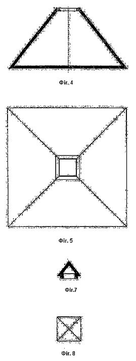
[0016] FIG. 4 is a perspective view of a cubic structure having another shape of the space energy implosion unit of FIG. 3;
[0017] FIG. 5 is an exploded perspective view of a space energy implosion unit according to another embodiment of the present invention;
[0018] FIG. 6 is a perspective view of a cubic structure having another shape of the space energy implosion unit of FIG. 5;
[0019] FIG. 7 is an exploded perspective view of a space energy implosion unit according to another embodiment of the present invention;
[0020] FIG. 8 is a perspective view of a cubic structure having another shape of the space energy implosion unit of FIG. 5;
[0021] FIG. 9 is an energy amplification generator according to an embodiment of the present invention;
[0022] FIG. 10 is a perspective view of a first geometrical structure of the energy amplification generator of FIG. 9;
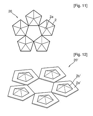
[0023] FIG. 11 is a perspective view of a second geometrical structure of the energy amplification generator of FIG. 9;
[0024] FIG. 12 is a perspective view of another shape of the second geometrical structure of FIG. 10;
[0025] FIG. 13 illustrates a stack structure of a second geometrical structure, a first geometrical structure, a plate structure, and a separation structure of the energy amplification generator of FIG. 9;
[0026] FIG. 14 is an energy amplification generator according to another embodiment of the present invention;
[0027] FIG. 15 is a perspective view of a first geometrical structure of the energy amplification generator of FIG. 14;
[0028] FIG. 16 is a perspective view of a second geometrical structure of the energy amplification generator of FIG. 14;
[0029] FIG. 17 is a perspective view of another shape of the second geometrical structure of FIG. 16;
[0030] FIG. 18 illustrates the structure in which a second geometrical structure, a first geometrical structure, a plate structure and separation structures are stacked, of the energy amplification generator of FIG. 9;
[0031] FIG. 19 is an energy amplification generator according to another embodiment of the present invention;
[0032] FIG. 20 is a perspective view of a first geometrical structure of the energy amplification generator of FIG. 19;
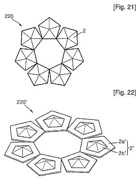
[0033] FIG. 21 is a perspective view of a second geometrical structure of the energy amplification generator of FIG. 19;
[0034] FIG. 22 is a perspective view of another shape of the second geometrical structure of FIG. 21;
[0035] FIG. 23 illustrates the structure in which a second geometrical structure, a first geometrical structure, a plate structure and separation structures are stacked, of the energy amplification generator of FIG. 19;
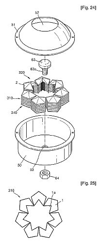
[0036] FIG. 24 is an energy amplification generator according to another embodiment of the present invention;
[0037] FIG. 25 is a perspective view of a first geometrical structure of the energy amplification generator of FIG. 24;
[0038] FIG. 26 is a perspective view of a second geometrical structure of the energy amplification generator of FIG. 24;
[0039] FIG. 27 is a perspective view of another shape of the second geometrical structure of FIG. 26;
[0040] FIG. 28 illustrates the structure in which a second geometrical structure, a first geometrical structure, a plate structure and separation structures are stacked, of the energy amplification generator of FIG. 25;
[0041] FIG. 29 is an energy amplification generator according to another embodiment of the present invention;
[0042] FIG. 30 is a perspective view of a first geometrical structure of the energy amplification generator of FIG. 29;
[0043] FIG. 31 is a perspective view of a second geometrical structure of the energy amplification generator of FIG. 29;
[0044] FIG. 32 is a perspective view of another shape of the second geometrical structure of FIG. 31;
[0045] FIG. 33 illustrates the structure in which a second geometrical structure, a first geometrical structure, a plate structure and separation structures are stacked, of the energy amplification generator of FIG. 29;
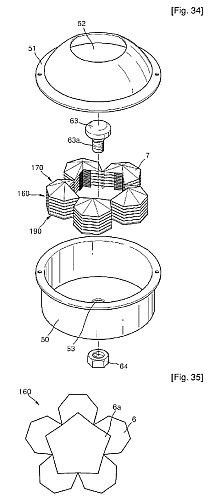
[0046] FIG. 34 is an energy amplification generator according to another embodiment of the present invention;
[0047] FIG. 35 is a perspective view of a first geometrical structure of the energy amplification generator of FIG. 34;
[0048] FIG. 36 is a perspective view of a second geometrical structure of the energy amplification generator of FIG. 34;
[0049] FIG. 37 is a perspective view of another shape of the second geometrical structure of FIG. 36;
[0050] FIG. 38 illustrates the structure in which a second geometrical structure, a first geometrical structure, a plate structure and separation structures are stacked, of the energy amplification generator of FIG. 34;
[0051] FIG. 39 is an energy amplification generator according to another embodiment of the present invention;
[0052] FIG. 40 is a perspective view of a first geometrical structure of the energy amplification generator of FIG. 39;
[0053] FIG. 41 is a perspective view of a second geometrical structure of the energy amplification generator of FIG. 39;
[0054] FIG. 42 is a perspective view of another shape of the second geometrical structure of FIG. 41;
[0055] FIG. 43 illustrates the structure in which a second geometrical structure, a first geometrical structure, a plate structure and separation structures are stacked, of the energy amplification generator of FIG. 39;
[0056] FIG. 44 is an energy amplification generator according to another embodiment of the present invention;
[0057] FIG. 45 is a perspective view of a first geometrical structure of the energy amplification generator of FIG. 44;
[0058] FIG. 46 is a perspective view of a second geometrical structure of the energy amplification generator of FIG. 44;
[0059] FIG. 47 is a perspective view of another shape of the second geometrical structure of FIG. 46;
[0060] FIG. 48 illustrates the structure in which a second geometrical structure, a first geometrical structure, a plate structure and separation structures are stacked, of the energy amplification generator of FIG. 44;
[0061] FIG. 49 shows a graph of Table 1 and illustrates the number of subjects before taking a space energy processing water;
[0062] FIG. 50 shows a graph of Table 2 and illustrates the number of subjects that show Erythema symptoms after taking a space energy processing water;
[0063] FIG. 51 shows a graph of Table 2 and illustrates the number of subjects that show Edema Papulation symptoms after taking a space energy processing water;
[0064] FIG. 52 shows a graph of Table 2 and illustrates the number of Oozing subjects after taking a space energy processing water;
[0065] FIG. 53 shows a graph of Table 2 and illustrates the number of Excoriation subjects symptoms after taking a space energy processing water;
[0066] FIG. 54 shows a graph of Table 2 and illustrates the number of Lichenification subjects after taking a space energy processing water; and
[0067] FIG. 55 is a graph showing tumor volumes of white rats that have drunk a general drinking water and white rats that have drunk a space energy processing water.


BEST MODE FOR CARRYING OUT THE INVENTION
[0068] The present invention will now be described more fully with reference to the accompanying drawings, in which exemplary embodiments of the invention are shown.
[0069] FIG. 1 is an exploded perspective view of a space energy implosion unit according to an embodiment of the present invention, and FIG. 2 is a perspective view of a cubic structure having another shape of the space energy implosion unit of FIG. 1.
[0070] Referring to FIG. 1, the space energy implosion unit according to an embodiment of the present invention includes a planar structure 1 having a regular pentagonal shape, a cubic structure 2 which is installed to be separated from an upper portion of the planar structure 1 and has a regular pentagonal pyramid shape, and a separation structure 3 which separates the planar structure 1 and the cubic structure 2 from each other and has a smaller area than areas of the planar structure 1 and the cubic structure 2. In this case, the separation structure 3 has a regular pentagonal shape. Here, the planar structure 1 is implemented as one or more pieces, and as the number of planar structures increases, the quantity of implosion of a space energy increases.
[0071] The cubic structure 2, the separation structure 3, and the planar structure 1 are stacked so that the arrangement angle of their respective sides is identical.
[0072] Here, a cubic structure 2' may also be applied in another shape. In other words, the cubic structure 2' may be implemented by forming a subcubic structure 2b' having a regular pentagonal pyramid shape having a smaller area than the area of a regular pentagonal planar plate 2a' on the planar plate 2a' as illustrated in FIG. 2.
[0073] FIG. 3 is an exploded perspective view of a space energy implosion unit according to another embodiment of the present invention, and FIG. 4 is a perspective view of a cubic structure having another shape of the space energy implosion unit of FIG. 3.
[0074] Referring to FIG. 3, the space energy implosion unit according to another embodiment of the present invention is similar to the space energy implosion unit shown in FIG. 1. The only difference therebetween is that, in FIG. 3, the space energy implosion unit further includes a planar cut groove 1a in which the planar structure 1 is cut to one side from the center and a cubic cut groove 2a in which the cubic structure 2 is cut to one side from the center. In this case, the separation structure 3 has a regular pentagonal shape but has a cut groove 3a in which the separation structure 3 is cut to one side from the center.
[0075] The cubic structure 2, the separation structure 3, and the planar structure 1 are stacked so that the arrangement angle of their respective sides is identical.
[0076] Here, a cubic structure 2' may also be applied in another shape. In other words, the cubic structure 2' may be implemented by forming a subcubic structure 2b' having a regular pentagonal pyramid shape having a smaller area than the area of a regular pentagonal planar plate 2a' on the planar plate 2a' as illustrated in FIG. 4. In this case, a cubic cut groove 2c in which the cubic structure 2 is cut to one side of the planar plate 2a from the center is formed in the cubic structure 2'.
[0077] FIG. 5 is an exploded perspective view of a space energy implosion unit according to another embodiment of the present invention, and FIG. 6 is a perspective view of a cubic structure having another shape of the space energy implosion unit of FIG. 5.
[0078] Referring to FIG. 5, the space energy implosion unit according to another embodiment of the present invention includes a planar structure 6 having a regular heptangular shape, a cubic structure 7 which is installed to be separated from an upper portion of the planar structure 6 and has a regular heptangular pyramid shape, and a separation structure 8 which separates the planar structure 6 and the cubic structure 7 from each other and has a smaller area than areas of the planar structure 6 and the cubic structure 7.
[0079] In this case, the separation structure 8 has a regular heptangular shape.
[0080] Here, the planar structure 6 is implemented as one or more pieces, and as the number of planar structures increases, the quantity of implosion of a space energy increases.
[0081] The cubic structure 7, the separation structure 8, and the planar structure 6 are stacked so that the arrangement angle of their respective sides is identical.
[0082] Here, a cubic structure 7' also be applied in another shape. In other words, the cubic structure 7' may be implemented by forming a subcubic structure 7b' having a regular heptangular pyramid shape having a smaller area than the area of a regular heptangular planar plate 7a' on the planar plate 7a' as illustrated in FIG. 6.
[0083] FIG. 7 is an exploded perspective view of a space energy implosion unit according to another embodiment of the present invention, and FIG. 8 is a perspective view of a cubic structure having another shape of the space energy implosion unit of FIG. 5.
[0084] Referring to FIG. 7, the space energy implosion unit according to another embodiment of the present invention is similar to the space energy implosion unit shown in FIG. 5. The only difference therebetween is that, in FIG. 7, the space energy implosion unit further includes a planar cut groove 6a in which the planar structure 6 is cut to two continuous sides from the center and a cubic cut groove 7a in which the cubic structure 7 is cut to two continuous sides from the center. In this case, the separation structure 8 has a regular pentagonal shape but has a cut groove 8a in which the separation structure 8 is cut to two continuous sides from the center.
[0085] The cubic structure 7, the separation structure 8, and the planar structure 6 are stacked so that the arrangement angle of their respective sides is identical.
[0086] Here, a cubic structure 7' may also be applied in another shape. In other words, the cubic structure 7' may be implemented by forming a subcubic structure 7b' having a regular heptangular pyramid shape having a smaller area than the area of a regular heptangular planar plate 7a' on the planar plate 7a' as illustrated in FIG. 8. In this case, a cubic cut groove 7c' in which the cubic structure 7' is cut to two continuous sides of the planar plate 7a' from the center is formed in the cubic structure 7'.
[0087] In the space energy implosion unit shown in FIGS. 1, 3, 5, and 7, the planar structure 1 implodes a space energy that is full in the universe due to its geometrical structure, and the cubic structure 2 concentrates the space energy imploded from the planar structure 1 due to its geometrical structure in a forward direction. When the cubic structure 2 is implemented in the shapes shown in FIGS. 2, 4, 6, and 8, the space energy that is full in the universe is imploded and simultaneously is concentrated in a forward direction.
[0088] An energy amplification generator using the space energy implosion unit according to exemplary embodiments of the present invention will now be described.
[0089] FIG. 9 is an energy amplification generator according to an embodiment of the present invention, FIG. 10 is a perspective view of a first geometrical structure of the energy amplification generator of FIG. 9, FIG. 11 is a perspective view of a second geometrical structure of the energy amplification generator of FIG. 9, FIG. 12 is a perspective view of another shape of the second geometrical structure of FIG. 10, and FIG. 13 illustrates a stack structure of a second geometrical structure, a first geometrical structure, a plate structure, and a separation structure of the energy amplification generator of FIG. 9. Here, like reference numerals in FIGS. 1 through 4 denote like elements having the same function.
[0090] Referring to FIG. 9, the energy amplification generator according to an embodiment of the present invention includes a first geometrical structure 10 in which vertices of each of five pieces of planar structures 1 having a regular pentagonal shape contact one another, a second geometrical structure 20 which is separated from an upper portion of the first geometrical structure 10 and in which vertices of each of five cubic structures 2 having a regular pentagonal pyramid shape contact one another, and a plurality of separation structures 3 which separate the first geometrical structure 10 and the second geometrical structure 20 from each other, are installed between the planar structure 1 and the cubic structure 2 and have a smaller area than areas of the planar structure 1 and the cubic structure 2.
[0091] The first geometrical structure 10 is one or two or more. The first geometrical structure 10 implodes a space energy that is full in the universe due to its geometrical structure to be indirectly and directly used.
[0092] The second geometrical structure 20 concentrates the space energy imploded by the first geometrical structure 10 in a forward direction.
[0093] Areas of the first geometrical structure 10 and the second geometrical structure 20 allow the quantity of the imploded space energy to be increased. In other words, in order to obtain a larger quantity of space energy, the number of stacked first geometrical structures 10 increases or the areas of the first and second geometrical structures 10 and 20 increase.
[0094] On the other hand, a second geometrical structure 20' may be modified in another shape. In other words, as illustrated in FIG. 12, in the second geometrical structure 20' a cubic structure 2 is implemented by forming a subcubic structure 2b' having a regular pentagonal pyramid shape having a smaller area than the area of a regular pentagonal planar plate 2a' on the planar plate 2a' Five cubic structures 2' are disposed on a plane so that vertices of each of five cubic structures 2' contact one another, thereby implementing the second geometrical structure 20' of the present application. The second geometrical structure 20' having the cubic structure 2' implodes the space energy and simultaneously concentrates the space energy in a forward direction.
[0095] A plate structure 40 supports the first geometrical structure 10 and has the same shape as that of the first geometrical structure 10. A plate hole 43 corresponding to a case hole 53 that will be described later is formed in the center of the plate structure 40.
[0096] The separation structures 3 may be installed among several first geometrical structures 10 so that the first geometrical structures 10 are separated from one another, or may be installed between the first geometrical structure 10 and the second geometrical structure 20 so that they are separated from each other, or may be installed between the first geometrical structure 10 and the plate structure 40 so that they are separated from each other. The separation structures 3 have a regular pentagonal shape and may be implemented to a predetermined thickness by stacking several plates or as a one product having a predetermined thickness.
[0097] The separation structures 3 allow the frequency of a radiated space energy to vary. In other words, the frequency of the space energy varies according to the thickness of the separation structures 3. The thickness of the separation structures 3 may be between 3 mm and 20 mm, and 7 mm thick separation structures 3 are used in the present embodiment.
[0098] A case 50 has a cover 51 in which a radiation sphere 52 through which a space energy is radiated in a forward direction is formed. The case hole 53 corresponding to the plate hole 43 is formed in the case 50.
[0099] The first geometrical structure 10, the separation structures 3, and the second geometrical structure 20 that will be stacked on the plate structure 40 are built in the case 50. In other words, the plate structure 40 on which the first and second geometrical structures 10 and 20 and the separation structures 3 are stacked, is fixed in the case 50 in such a way that a bolt portion 63a of a fixing member 63 perforates the plate hole 43 and the case hole 53 and then is engaged with a nut 64 in the rear of the case 50, as illustrated in FIG. 9.
[0100] An energy amplification generator according to another embodiment of the present invention will now be described.
[0101] FIG. 14 is an energy amplification generator according to another embodiment of the present invention, FIG. 15 is a perspective view of a first geometrical structure of the energy amplification generator of FIG. 14, FIG. 16 is a perspective view of a second geometrical structure of the energy amplification generator of FIG. 14, FIG. 17 is a perspective view of another shape of the second geometrical structure of FIG. 16, and FIG. 18 illustrates the structure in which a second geometrical structure, a first geometrical structure, a plate structure and separation structures are stacked, of the energy amplification generator of FIG. 9. Here, like reference numerals in FIG. 9 denote like elements having the same function.
[0102] Referring to FIG. 14, the energy amplification generator according to another embodiment of the present invention includes a first geometrical structure 110 in which vertices of each of five pieces of planar structures 1 having a regular pentagonal shape contact one another, a second geometrical structure 120 which is separated from an upper portion of the first geometrical structure 110 and in which vertices of each of five cubic structures 2 having a regular pentagonal pyramid shape contact one another, and a plurality of separation structures 3 which separate the first geometrical structure 110 and the second geometrical structure 120 from each other, are installed between the planar structure 1 and the cubic structure 2 and have a smaller area than areas of the planar structure 1 and the cubic structure 2.
[0103] The first geometrical structure 110 is one or two or more. The first geometrical structure 110 implodes a space energy that is full in the universe due to its geometrical structure to be indirectly and directly used.
[0104] The second geometrical structure 120 concentrates the space energy imploded by the first geometrical structure 110 in a forward direction.
[0105] Areas of the first geometrical structure 110 and the second geometrical structure 120 allow the quantity of the imploded space energy to be increased. In other words, in order to obtain a larger quantity of space energy, the number of stacked first geometrical structures 110 increases or the areas of the first and second geometrical structures 110 and 120 increase.
[0106] In this case, in the first geometrical structure 110, the planar structure 1 further includes a planar cut groove 1a in which the planar structure 1 is cut to one side between two contacting vertices from the center, and the cubic structure 2 further includes a cubic cut groove 2a in which the cubic structure 2 is cut to one side between two contacting vertices from the center.
[0107] In addition, the separation structures 3 have a regular pentagonal shape but also have a cut groove 3a in which each of the separation structures 3 is cut to one side from the center.
[0108] The cubic structure 2, the separation structures 3, and the planar structure 1 are stacked that the arrangement angle of their respective sides are identical.
[0109] On the other hand, a second geometrical structure 120' may be modified in another shape. In other words, as illustrated in FIG. 17, a cubic structure 2' of the second geometrical structure 120' is implemented by forming a subcubic structure 2b' having a regular pentagonal pyramid shape having a smaller area than the area of a regular pentagonal planar plate 2a on the planar plate 2a'. At this time, a cubic cut groove 2c' in which the cubic structure 2' is cut to one side between two contacting vertices of the planar plate 2a' from the center is formed in the cubic structure 2'. Five cubic structures 2' are disposed on a plane so that vertices of each of five cubic structures 2' contact one another, thereby implementing the second geometrical structure 120' of the present application.
[0110] A plate structure 140 supports the first geometrical structure 110 and has the same shape as that of the first geometrical structure 110. A plate hole 143 corresponding to a case hole 53 is formed in the center of the plate structure 140.
[0111] The case 50, the cover 51, the radiation sphere 52, the case hole 53, the fixing member 63, the bolt portion 63a, and the nut 64 are the same as in the energy amplification generator shown in FIG. 9 and thus, a detailed description thereof will be omitted.
[0112] An energy amplification generator according to another embodiment of the present invention will now be described.
[0113] FIG. 19 is an energy amplification generator according to another embodiment of the present invention, FIG. 20 is a perspective view of a first geometrical structure of the energy amplification generator of FIG. 19, FIG. 21 is a perspective view of a second geometrical structure of the energy amplification generator of FIG. 19, FIG. 22 is a perspective view of another shape of the second geometrical structure of FIG. 21, and FIG. 23 illustrates the structure in which a second geometrical structure, a first geometrical structure, a plate structure and separation structures are stacked, of the energy amplification generator of FIG. 19. Here, like reference numerals in FIGS. 9 and 14 denote like elements having the same function.
[0114] Referring to FIG. 19, the energy amplification generator according to another embodiment of the present invention includes a first geometrical structure 210 in which vertices of each of seven pieces of planar structures 1 having a regular pentagonal shape contact one another, a second geometrical structure 220 which is separated from an upper portion of the first geometrical structure 210 and in which vertices of each of seven cubic structures 2 having a regular pentagonal pyramid shape contact one another, and a plurality of separation structures 3 which separate the first geometrical structure 210 and the second geometrical structure 220 from each other, are installed between the planar structure 1 and the cubic structure 2 and have a smaller area than areas of the planar structure 1 and the cubic structure 2.
[0115] The first geometrical structure 210 is one or two or more. The first geometrical structure 210 implodes a space energy that is full in the universe due to its geometrical structure to be indirectly and directly used.
[0116] The second geometrical structure 220 concentrates the space energy imploded by the first geometrical structure 210 in a forward direction.
[0117] Areas of the first geometrical structure 210 and the second geometrical structure 220 allow the quantity of the imploded space energy to be increased. In other words, in order to obtain a larger quantity of space energy, the number of stacked first geometrical structures 210 increases or the areas of the first and second geometrical structures 210 and 220 increase.
[0118] The cubic structure 2, the separation structures 3, and the planar structure 1 are stacked that the arrangement angle of their respective sides are identical.
[0119] On the other hand, a second geometrical structure 220' may be modified in another shape. In other words, as illustrated in FIG. 22, a cubic structure 2' of the second geometrical structure 220' is implemented by forming a subcubic structure 2b' having a regular pentagonal pyramid shape having a smaller area than the area of a regular pentagonal planar plate 2a' on the planar plate 2a'. Seven cubic structures 2' are disposed on a plane so that vertices of each of seven cubic structures 2' contact one another, thereby implementing the second geometrical structure 220' of the present application.
[0120] A plate structure 240 supports the first geometrical structure 210 and has the same shape as that of the first geometrical structure 210. A plate hole 243 corresponding to a case hole 53 is formed in the center of the plate structure 240.
[0121] The case 50, the cover 51, the radiation sphere 52, the case hole 53, the fixing member 63, the bolt portion 63a, and the nut 64 are the same as in the energy amplification generator shown in FIGS. 9 and 14 and thus, a detailed description thereof will be omitted.
[0122] An energy amplification generator according to another embodiment of the present invention will now be described.
[0123] FIG. 24 is an energy amplification generator according to another embodiment of the present invention, FIG. 25 is a perspective view of a first geometrical structure of the energy amplification generator of FIG. 24, FIG. 26 is a perspective view of a second geometrical structure of the energy amplification generator of FIG. 24, FIG. 27 is a perspective view of another shape of the second geometrical structure of FIG. 26, and FIG. 28 illustrates the structure in which a second geometrical structure, a first geometrical structure, a plate structure and separation structures are stacked, of the energy amplification generator of FIG. 25. Here, like reference numerals in FIGS. 9, 14, and 19 denote like elements having the same function.
[0124] Referring to FIG. 24, the energy amplification generator according to another embodiment of the present invention includes a first geometrical structure 310 in which vertices of each of seven pieces of planar structures 1 having a regular pentagonal shape contact one another, a second geometrical structure 320 which is separated from an upper portion of the first geometrical structure 310 and in which vertices of each of seven cubic structures 2 having a regular pentagonal pyramid shape contact one another, and a plurality of separation structures 3 which separate the first geometrical structure 310 and the second geometrical structure 320 from each other, are installed between the planar structure 1 and the cubic structure 2 and have a smaller area than areas of the planar structure 1 and the cubic structure 2.
[0125] The first geometrical structure 310 is one or two or more. The first geometrical structure 310 implodes a space energy that is full in the universe due to its geometrical structure to be indirectly and directly used.
[0126] The second geometrical structure 320 concentrates the space energy imploded by the first geometrical structure 310 in a forward direction.
[0127] Areas of the first geometrical structure 310 and the second geometrical structure 320 allow the quantity of the imploded space energy to be increased. In other words, in order to obtain a larger quantity of space energy, the number of stacked first geometrical structures 310 increases or the areas of the first and second geometrical structures 310 and 320 increase.
[0128] In this case, in the first geometrical structure 310, the planar structure 1 further includes a planar cut groove 1a in which the planar structure 1 is cut to one side between two contacting vertices from the center, and the cubic structure 2 further includes a cubic cut groove 2a in which the cubic structure 2 is cut to one side between two contacting vertices from the center.
[0129] In addition, the separation structures 3 have a regular pentagonal shape but also have a cut groove 3a in which each of the separation structures 3 is cut to one side from the center.
[0130] The cubic structure 2, the separation structures 3, and the planar structure 1 are stacked that the arrangement angle of their respective sides are identical.
[0131] On the other hand, a second geometrical structure 320' may be modified in another shape. In other words, as illustrated in FIG. 27, a cubic structure 2' of the second geometrical structure 320' is implemented by forming a subcubic structure 2b' having a regular pentagonal pyramid shape having a smaller area than the area of a regular pentagonal planar plate 2a' on the planar plate 2a'. At this time, a cubic cut groove 2c' in which the cubic structure 2' is cut to one side between two contacting vertices of the planar plate 2a' from the center is formed in the cubic structure 2'. Seven cubic structures 2' are disposed on a plane so that vertices of each of seven cubic structures 2' contact one another, thereby implementing the second geometrical structure 320' of the present application.
[0132] A plate structure 340 supports the first geometrical structure 310 and has the same shape as that of the first geometrical structure 310. A plate hole 343 corresponding to a case hole 53 is formed in the center of the plate structure 340.
[0133] The case 50, the cover 51, the radiation sphere 52, the case hole 53, the fixing member 63, the bolt portion 63a, and the nut 64 are the same as in the energy amplification generator shown in FIGS. 9, 14, and 19, and thus, a detailed description thereof will be omitted.
[0134] An energy amplification generator according to another embodiment of the present invention will now be described.
[0135] FIG. 29 is an energy amplification generator according to another embodiment of the present invention, FIG. 30 is a perspective view of a first geometrical structure of the energy amplification generator of FIG. 29, FIG. 31 is a perspective view of a second geometrical structure of the energy amplification generator of FIG. 29, FIG. 32 is a perspective view of another shape of the second geometrical structure of FIG. 31, and FIG. 33 illustrates the structure in which a second geometrical structure, a first geometrical structure, a plate structure and separation structures are stacked, of the energy amplification generator of FIG. 29. Here, like reference numerals in FIGS. 5 through 8 denote like elements having the same function.
[0136] Referring to FIG. 29, the energy amplification generator according to another embodiment of the present invention includes a first geometrical structure 60 in which both-end vertices at two continuous sides of each of five pieces of planar structures 6 having a regular heptangular shape contact one another, a second geometrical structure 70 which is separated from an upper portion of the first geometrical structure 60 and in which both-end vertices at two continuous sides of each of five cubic structures 7 having a regular heptangular pyramid shape contact one another, and a plurality of separation structures 8 which separate the first geometrical structure 60 and the second geometrical structure 70 from each other, are installed between the planar structure 6 and the cubic structure 7 and have a smaller area than areas of the planar structure 6 and the cubic structure 7.
[0137] The first geometrical structure 60 is one or two or more. The first geometrical structure 60 implodes a space energy that is full in the universe due to its geometrical structure to be indirectly and directly used.
[0138] The second geometrical structure 70 concentrates the space energy imploded by the first geometrical structure 60 in a forward direction.
[0139] Areas of the first geometrical structure 60 and the second geometrical structure 70 allow the quantity of the imploded space energy to be increased. In other words, in order to obtain a larger quantity of space energy, the number of stacked first geometrical structures 60 increases or the areas of the first and second geometrical structures 60 and 70 increase.
[0140] On the other hand, a second geometrical structure 70' may be modified in another shape. In other words, as illustrated in FIG. 32, a cubic structure 7' of the second geometrical structure 70' is implemented by forming a subcubic structure 7b' having a regular heptangular pyramid shape having a smaller area than the area of a regular heptangular planar plate 7a' on the planar plate 7a'. Five cubic structures 7' are disposed on a plane so that both-end vertices at two continuous sides of each of five cubic structures 7' contact one another, thereby implementing the second geometrical structure 70' of the present application. The second geometrical structure 70' having the cubic structure 7' implodes a space energy and simultaneously, concentrates the space energy in a forward direction.
[0141] A plate structure 90 supports the first geometrical structure 60 and has the same shape as that of the first geometrical structure 60. A plate hole 93 corresponding to a case hole 53 that will be described later is formed in the center of the plate structure 90.
[0142] The separation structures 8 may be installed among several first geometrical structures 60 so that the first geometrical structures 60 are separated from one another, or may be installed between the first geometrical structure 60 and the second geometrical structure 70 so that they are separated from each other, or may be installed between the first geometrical structure 60 and the plate structure 90 so that they are separated from each other. The separation structures 8 have a regular heptangular shape and may be implemented to a predetermined thickness by stacking several plates or as a one product having a predetermined thickness.
[0143] The separation structures 8 allow the frequency of a radiated space energy to vary. In other words, the frequency of the space energy varies according to the thickness of the separation structures 8. The thickness of the separation structures 8 may be between 3 mm and 20 mm, and 7 mm thick separation structures 3 are used in the present embodiment.
[0144] A case 50 has a cover 51 in which a radiation sphere 52 through which a space energy is radiated in a forward direction is formed. The case hole 53 corresponding to the plate hole 93 is formed in the case 50.
[0145] The first geometrical structure 60, the separation structures 8, and the second geometrical structure 70 that will be stacked on the plate structure 90 are built in the case 50. In other words, the plate structure 90 on which the first and second geometrical structures 60 and 70 and the separation structures 8 are stacked, is fixed in the case 50 in such a way that a bolt portion 63a of a fixing member 63 perforates the plate hole 93 and the case hole 53 and then is engaged with a nut 64 in the rear of the case 50, as illustrated in FIG. 29.
[0146] An energy amplification generator according to another embodiment of the present invention will now be described.
[0147] FIG. 34 is an energy amplification generator according to another embodiment of the present invention, FIG. 35 is a perspective view of a first geometrical structure of the energy amplification generator of FIG. 34, FIG. 36 is a perspective view of a second geometrical structure of the energy amplification generator of FIG. 34, FIG. 37 is a perspective view of another shape of the second geometrical structure of FIG. 36, and FIG. 38 illustrates the structure in which a second geometrical structure, a first geometrical structure, a plate structure and separation structures are stacked, of the energy amplification generator of FIG. 34. Here, like reference numerals in FIG. 29 denote like elements having the same function.
[0148] Referring to FIG. 34, the energy amplification generator according to another embodiment of the present invention includes a first geometrical structure 160 in which both-end vertices at two continuous sides of each of five pieces of planar structures 6 having a regular heptangular shape contact one another, a second geometrical structure 170 which is separated from an upper portion of the first geometrical structure 160 and in which both-end vertices at two continuous sides of each of five cubic structures 7 having a regular heptangular pyramid shape contact one another, and a plurality of separation structures 8 which separate the first geometrical structure 160 and the second geometrical structure 170 from each other, are installed between the planar structure 6 and the cubic structure 7 and have a smaller area than areas of the planar structure 6 and the cubic structure 7.
[0149] The first geometrical structure 160 is one or two or more. The first geometrical structure 160 implodes a space energy that is full in the universe due to its geometrical structure to be indirectly and directly used.
[0150] The second geometrical structure 170 concentrates the space energy imploded by the first geometrical structure 160 in a forward direction.
[0151] Areas of the first geometrical structure 160 and the second geometrical structure 170 allow the quantity of the imploded space energy to be increased. In other words, in order to obtain a larger quantity of space energy, the number of stacked first geometrical structures 160 increases or the areas of the first and second geometrical structures 160 and 170 increase.
[0152] In this case, in the first geometrical structure 160, the planar structure 6 further includes a planar cut groove 6a in which the planar structure 6 is cut to two continuous sides between two contacting vertices from the center, and the cubic structure 7 further includes a cubic cut groove 7a in which the cubic structure 7 is cut to two continuous sides between two contacting vertices from the center. In addition, the separation structures 8 have a regular heptangular shape but also have a cut groove 8a in which each of the separation structures 8 is cut to two continuous sides from the center.
[0153] The cubic structure 7, the separation structures 8, and the planar structure 6 are stacked that the arrangement angle of their respective sides are identical.
[0154] On the other hand, a second geometrical structure 170' may be modified in another shape. In other words, as illustrated in FIG. 37, a cubic structure 7' of the second geometrical structure 170' is implemented by forming a subcubic structure 7b' having a regular heptangular pyramid shape having a smaller area than the area of a regular heptangular planar plate 7a' on the planar plate 7a'. At this time, a cubic cut groove 7c' in which the cubic structure 7' is cut to two continuous sides between two contacting vertices of the planar plate 7a' from the center is formed in the cubic structure 7'. Five cubic structures 7' are disposed on a plane so that both-end vertices at two continuous sides of each of five cubic structures 7' contact one another, thereby implementing the second geometrical structure 170' of the present application.
[0155] A plate structure 190 supports the first geometrical structure 160 and has the same shape as that of the first geometrical structure 160. A plate hole 193 corresponding to a case hole 53 that will be described later is formed in the center of the plate structure 190.
[0156] A case 50, a cover 51, a radiation sphere 52, a case hole 53, a fixing member 63, a bolt portion 63a, and a nut 64 are the same as in the energy amplification generator shown in FIG. 29 and thus, a detailed description thereof will be omitted.
[0157] An energy amplification generator according to another embodiment of the present invention will now be described.
[0158] FIG. 39 is an energy amplification generator according to another embodiment of the present invention, FIG. 40 is a perspective view of a first geometrical structure of the energy amplification generator of FIG. 39, FIG. 41 is a perspective view of a second geometrical structure of the energy amplification generator of FIG. 39, FIG. 42 is a perspective view of another shape of the second geometrical structure of FIG. 41, and FIG. 43 illustrates the structure in which a second geometrical structure, a first geometrical structure, a plate structure and separation structures are stacked, of the energy amplification generator of FIG. 39. Here, like reference numerals in FIGS. 29 and 34 denote like elements having the same function.
[0159] Referring to FIG. 39, the energy amplification generator according to another embodiment of the present invention includes a first geometrical structure 260 in which both-end vertices at two continuous sides of each of seven pieces of planar structures 6 having a regular heptangular shape contact one another, a second geometrical structure 270 which is separated from an upper portion of the first geometrical structure 260 and in which both-end vertices at two continuous sides of each of seven cubic structures 7 having a regular heptangular pyramid shape contact one another, and a plurality of separation structures 8 which separate the first geometrical structure 260 and the second geometrical structure 270 from each other, are installed between the planar structure 6 and the cubic structure 7 and have a smaller area than areas of the planar structure 6 and the cubic structure 7.
[0160] The first geometrical structure 260 is one or two or more. The first geometrical structure 260 implodes a space energy that is full in the universe due to its geometrical structure to be indirectly and directly used.
[0161] The second geometrical structure 270 concentrates the space energy imploded by the first geometrical structure 260 in a forward direction.
[0162] Areas of the first geometrical structure 260 and the second geometrical structure 270 allow the quantity of the imploded space energy to be increased. In other words, in order to obtain a larger quantity of space energy, the number of stacked first geometrical structures 260 increases or the areas of the first and second geometrical structures 260 and 270 increase.
[0163] The cubic structure 7, the separation structures 8, and the planar structure 6 are stacked that the arrangement angle of their respective sides are identical.
[0164] On the other hand, a second geometrical structure 270' may be modified in another shape. In other words, as illustrated in FIG. 42, a cubic structure 7' of the second geometrical structure 270' is implemented by forming a subcubic structure 7b' having a regular heptangular pyramid shape having a smaller area than the area of a regular heptangular planar plate 7a' on the planar plate 7a'. Seven cubic structures 7' are disposed on a plane so that both-end vertices at two continuous sides of each of seven cubic structures 7' contact one another, thereby implementing the second geometrical structure 270' of the present application.
[0165] A plate structure 290 supports the first geometrical structure 260 and has the same shape as that of the first geometrical structure 260. A plate hole 293 corresponding to a case hole 53 that will be described later is formed in the center of the plate structure 290.
[0166] A case 50, a cover 51, a radiation sphere 52, a case hole 53, a fixing member 63, a bolt portion 63a, and a nut 64 are the same as in the energy amplification generator shown in FIGS. 29 and 34 and thus, a detailed description thereof will be omitted.
[0167] An energy amplification generator according to another embodiment of the present invention will now be described.
[0168] FIG. 44 is an energy amplification generator according to another embodiment of the present invention, FIG. 45 is a perspective view of a first geometrical structure of the energy amplification generator of FIG. 44, FIG. 46 is a perspective view of a second geometrical structure of the energy amplification generator of FIG. 44, FIG. 47 is a perspective view of another shape of the second geometrical structure of FIG. 46, and FIG. 48 illustrates the structure in which a second geometrical structure, a first geometrical structure, a plate structure and separation structures are stacked, of the energy amplification generator of FIG. 44. Here, like reference numerals in FIGS. 29, 34, and 39 denote like elements having the same function.
[0169] Referring to FIG. 44, the energy amplification generator according to another embodiment of the present invention includes a first geometrical structure 360 in which both-end vertices at two continuous sides of each of seven pieces of planar structures 6 having a regular heptangular shape contact one another, a second geometrical structure 370 which is separated from an upper portion of the first geometrical structure 360 and in which both-end vertices at two continuous sides of each of seven cubic structures 7 having a regular heptangular pyramid shape contact one another, and a plurality of separation structures 8 which separate the first geometrical structure 360 and the second geometrical structure 370 from each other, are installed between the planar structure 6 and the cubic structure 7 and have a smaller area than areas of the planar structure 6 and the cubic structure 7. Here, the first geometrical structure 360 is one or two or more.
[0170] The first geometrical structure 360 implodes a space energy that is full in the universe due to its geometrical structure to be indirectly and directly used.
[0171] The second geometrical structure 370 concentrates the space energy imploded by the first geometrical structure 360 in a forward direction.
[0172] Areas of the first geometrical structure 360 and the second geometrical structure 370 allow the quantity of the imploded space energy to be increased. In other words, in order to obtain a larger quantity of space energy, the number of stacked first geometrical structures 360 increases or the areas of the first and second geometrical structures 360 and 370 increase.
[0173] In this case, in the first geometrical structure 310, the planar structure 6 further includes a planar cut groove 6a in which the planar structure 6 is cut to two continuous sides between two contacting vertices from the center, and the cubic structure 7 further includes a cubic cut groove 7a in which the cubic structure 7 is cut to two continuous sides between two contacting vertices from the center. In addition, the separation structures 8 have a regular heptangular shape but also have a cut groove 8a in which each of the separation structures 8 is cut to two continuous sides from the center.
[0174] The cubic structure 7, the separation structures 8, and the planar structure 6 are stacked that the arrangement angle of their respective sides are identical.
[0175] On the other hand, a second geometrical structure 370' may be modified in another shape. In other words, as illustrated in FIG. 47, a cubic structure 7' of the second geometrical structure 370' is implemented by forming a subcubic structure 7b' having a regular heptangular pyramid shape having a smaller area than the area of a regular heptangular planar plate 7a' on the planar plate 7a'. At this time, a cubic cut groove 7c' in which the cubic structure 7' is cut to two continuous sides between two contacting vertices of the planar plate 7a' from the center is formed in the cubic structure 7'. Seven cubic structures 7' are disposed on a plane so that both-end vertices at two continuous sides of each of seven cubic structures 7' contact one another, thereby implementing the second geometrical structure 370' of the present application.
[0176] A plate structure 390 supports the first geometrical structure 360 and has the same shape as that of the first geometrical structure 360. A plate hole 393 corresponding to a case hole 53 that will be described later is formed in the center of the plate structure 390.
[0177] A case 50, a cover 51, a radiation sphere 52, a case hole 53, a fixing member 63, a bolt portion 63a, and a nut 64 are the same as in the energy amplification generator shown in FIGS. 29, 34, and 39 and thus, a detailed description thereof will be omitted.
[0178] The space energy implosion unit shown in FIGS. 9, 14, 19, 24, 29, 34, 39, and 44, a space energy which is a kind of a torsion field, i.e., a small space energy that is full in the universe, is imploded and is converted into a usable energy to be directly or indirectly used due to the above-described geometrical structure.
[0179] An implosion mechanism of a space energy has not clearly been investigated scientifically yet. However, the present applicant has found a structure in which a space energy can be most effectively radiated, through many repetitive experiments. Such a space energy does not have the intensity that can be directly perceived by human's five senses but its existence can be verified through several experiments.
[0180] In other words, when a case where a space energy is radiated on a particular object and a case where a space energy is not radiated on a particular object are compared, if any difference therebetween occurs, it can be inductively known that a space energy exists. Hereinafter, various experimental examples for verifying the existence of a space energy will be described.
[0181] (1) Cancer Cell Growth Experiment
[0182] FIG. 55 is a graph showing tumor volumes of white rats that have drunk a general drinking water and white rats that have drunk a space energy processing water.
[0183] The present experiment has been carried out by professor Hyunwon Kim of Wonju medical college of the Yonsei University, April 2004 and his researchers.
[0184] In order to carry out the present experiment, after two chambers where experiment white rats C56BL/6 live were prepared, a water supply tube in which a processing water processed by radiating a space energy on a general drinking water was put was installed in one of the chambers, and a water supply tube in which a general drinking water was put was installed in the other one (a control group) so that the space energy processing water or the general drinking water can be freely taken by subjects from the water supply tubes that are put in each chamber. The same number of experiment white rats C56BL 6 as experiment white rats C56BL/6 to whose subcutaneous tissues malignant skin cancer cells B16 Melanoma are injected were put in each chamber and tumor volumes were observed according to days for 20 days.
[0185] In the graph of FIG. 55, a portion marked by control indicates tumor volumes of white rats that have drunk a general drinking water according to days, and a portion marked by life energy indicates tumor volumes of white rats that have drunk a space energy processing water according to days.
[0186] As a result of measuring tumor volumes for 20 days, as shown in the graph of FIG. 55, in case of white rats that have drunk a space energy processing water that is imploded by an energy amplification generator, tumor volumes are very smaller than those of the control group.
[0187] As known from the graph of FIG. 55, in case of white rats (life energy) that have drunk a space energy processing water, tumor volumes are very smaller than those of white rats (control) that have drunk a general drinking water. Thus, the space energy processing water makes an anticancer action on a living body of a white rat. That is, the existence of the space energy can be verified from the graph.
[0188] (2) Clinical Tests Relating to Whether a Processing Water that is Processed by a Space Energy Affects Infant Atopic Patients or not.
[0189] FIG. 49 shows a graph of Table 1 and illustrates the number of subjects before taking a space energy processing water. Also, FIG. 50 shows a graph of Table 2 and illustrates the number of subjects that show Erythema symptoms after taking a space energy processing water, FIG. 51 shows a graph of Table 2 and illustrates the number of subjects that show Edema Papulation symptoms after taking a space energy processing water, FIG. 52 shows a graph of Table 2 and illustrates the number of Oozing subjects after taking a space energy processing water, FIG. 53 shows a graph of Table 2 and illustrates the number of Excoriation subjects symptoms after taking a space energy processing water, and FIG. 54 shows a graph of Table 2 and illustrates the number of Lichenification subjects after taking a space energy processing water.
[0190] The clinical tests have been carried out at Chungnoi oriental hospital (principal Jaekyu Ryu) located in the third floor, Winplus commercial building, 507, Daechi-dong, Kangnam-gu, Seoul, Republic of Korea, in early 2005. The clinical tests are experiments for verifying whether, when infant atopic patients took a space processing water, the space processing water affects the infant atopic patients clinically or not.
[0191] In the clinical tests, D-company spring water (hereinafter, referred to as a space energy processing water) in which the space energy that is radiated from the energy amplification generator according to the present invention is investigated for 10 days, was taken by 40 infant atopic patients (male 15, female 25) of 0-4 years old who visited at the Chungnoi oriental hospital for atopic treatment.
[0192] In the clinical tests, five hypotheses that, when infant atopic patients took the space energy processing water, there may be a difference between before and after taking the space energy processing water were formed, and an atopic index ((SCORAD: SCORing Atopic Dermatitis) index)) before and after taking the space energy processing water was measured, thereby verifying a clinical effect of a space energy processing water.
[0193] Here, the atopic index (SCORAD index) has clinical significance only when the whole body skin status, partial skin photos and itching are simultaneously checked and a resultant value thereof is obtained. However, there was a difficulty for checking the whole body skin status and itching because subjects were infants. Thus, Erythema, Edema Papulation, Oozing, Excoriation, and Lichenification which are main atopic symptoms were scored and classified.
[0194] The symptoms of atopic patients before taking a space energy processing water are shown in Table 1 and FIG. 50.
[0000]
TABLE 1
Subjects Symptoms before taking Space Energy Processing Water
Edema Excori- Licheni-
Status Erythema Papulation Oozing ation fication
Severe(III) 5 3 3 0 2
Moderate(II) 25 20 15 1 1
Mild(I) 8 17 2 5 1
0(No 2 0 20 34 36
symptom)
[0195] Table 1 is expressed as a graph, as shown in FIG. 51.
[0196] Five hypotheses that, when infant atopic patients took a space energy processing water, there may be a difference between before and after taking the space energy processing water are as described below.
[0197] (a) Hypothesis 1
[0198] Erythema symptoms of infant atopic patients who took 200-300 cc of a space energy processing spring water for one month three times a day for 10 days may be different from those before taking the space energy processing spring water.
[0199] (b) Hypothesis 2
[0200] Edema Papulation symptoms of infant atopic patients who took 200-300 cc of a space energy processing spring water for one month three times a day for 10 days may be different from those before taking the space energy processing spring water.
[0201] (c) Hypothesis 3
[0202] Oozing symptoms of infant atopic patients who took 200-300 cc of a space energy processing spring water for one month three times a day for 10 days may be different from those before taking the space energy processing spring water.
[0203] (d) Hypothesis 4
[0204] Excoriation symptoms of infant atopic patients who took 200-300 cc of a space energy processing spring water for one month three times a day for 10 days may be different from those before taking the space energy processing spring water.
[0205] (e) Hypothesis 5
[0206] Lichenification symptoms of infant atopic patients who took 200-300 cc of a space energy processing spring water for one month three times a day for 10 days may be different from those before taking the space energy processing spring water.
[0207] The result of the clinical tests is shown in Table 2.
[0000]
TABLE 2
Subjects: Symptoms after taking Space Energy Processing Water.
Edema Excori- Licheni-
Status Erythema Papulation Oozing ation fication
Severe(III) 0 1 1 0 2
Moderate(II) 14 10 0 1 1
Mild(I) 13 12 1 4 1
0(No 13 17 38 35 36
symptom)
[0208] (a) Result of Hypothesis 1
[0209] In Erythema symptoms of infant atopic patients, there was a significant difference between before taking 200-300 cc of the space energy processing water three times a day for 10 days and after taking it and treatment. In other words, as illustrated in FIG. 50, in Erythema symptoms of patients after treatment by taking the space energy processing water, the status of a number of patients who belong to 'severe' and 'moderate' of Table 2 is moved to the status of mild or '0(no symptom)', that is, symptoms have been improved.
[0210] (b) Result of Hypothesis 2
[0211] In Edema Papulation symptoms of infant atopic patients, there was a significant difference between before taking 200-300 cc of the space energy processing water three times a day for 10 days and after taking it and treatment. In other words, as illustrated in FIG. 51, in Edema Papulation symptoms of patients after treatment by taking the space energy processing water, the status of a number of patients is moved to the status of 0(no symptom), that is, symptoms have been improved.
[0212] (c) Result of Hypothesis 3
[0213] In Oozing symptoms of infant atopic patients, there was a significant difference between before taking 200-300 cc of the space energy processing water three times a day for 10 days and after taking it and treatment. In other words, as illustrated in FIG. 52, in Oozing symptoms of patients after treatment by taking the space energy processing water, the status of a number of patients is moved to the status of '0(no symptom)', that is, symptoms have been improved.
[0214] (d) Result of Hypothesis 4
[0215] In Excoriation symptoms of infant atopic patients, there was no significant difference between before taking 200-300 cc of the space energy processing water three times a day for 10 days and after taking it and treatment. In other words, as illustrated in FIG. 53, in Excoriation symptoms of patients after treatment by taking the space energy processing water, the Excoriation symptoms of most subjects were not severe, and thus, it was a difficulty for finding significance in comparison with the results before and after taking the space energy processing water. However, it was verified by naked eyes that the skin status after taking the space energy processing water is more smooth than before taking the space energy processing water.
[0216] (e) Result of Hypothesis 5
[0217] In Lichenification symptoms of infant atopic patients, there was no significant difference between before taking 200-300 cc of the space energy processing water three times a day for 10 days and after taking it and treatment. Since Lichenification symptoms occur in adult chronic serious-case patients having a long disease-contraction period, as illustrated in FIG. 54, many Lichenification symptoms have not been found in infants having a short disease-contraction period of less than 4 years old.
[0218] As verified in the above results, symptoms such as Erythema (hypothesis 1), Edema Papulation (hypothesis 2), Oozing (hypothesis 3), and Excoriation (hypothesis 4) have been improved. Although, in case of Lichenification (hypothesis 5) symptoms, there was no significant difference, the existence of a space energy can be verified according to the results of hypotheses 1, 2, 3, and 4.
[0219] The space energy radiated from the energy amplification generator according to the present invention allows a living body energy to be activated, as verified in the above-described cancer cell growth experiments or clinical tests. However, the space energy shows various effects in the following fields.
[0220] If the space energy radiated from the energy amplification generator is radiated on a plant, the growth of the plant is brought on, and chemical reactions such as decay etc. are suppressed. Thus, it can be understood from the results that one action of the space energy according to the present invention is a non-ionization action for suppressing ionic polarization. Such a phenomenon occurs even in a human body and is as described above.
[0221] In addition, when the space energy is radiated on milk at about 20[deg.] C. for about three weeks, milk is not decayed but can be eaten and is changed into yogurt in which lactobacillus that has also been used in a health food is contained.
[0222] In addition, when the space energy is radiated on a strawberry for two months, the strawberry is not decayed or acidified, is dried and dehydrated and is changed into a glutinous shape like raisins. This does not harm the human body when man takes the strawberry. This represents a processing method by which foods can be kept for a long time, comparing when strawberries are kept in a general environment, for more than three days, they begin to be deformed and be decayed after several days have elapsed.
[0223] In addition, when the space energy is radiated on a cold-storage apple for about two or more years, due to moisture evaporation, part of the epidermis is crumpled and its interior fleshiness is not greatly different from the fleshiness of an original apple. In this way, when the present invention is applied to living body objects around man, their living body energy can be preserved and reinforced.
[0224] While the present invention has been particularly shown and described with reference to exemplary embodiments thereof, it will be understood by those skilled in the art that various changes in form and details may be made therein without departing from the spirit and scope of the invention as defined by the following claims.
INDUSTRIAL APPLICABILITY
[0225] As described above, in the space energy implosion unit and the energy amplification generator using the same according to the present invention, a space energy which is a kind of a torsion field and is imploded in a particular geometrical shape, is more effectively imploded so that the space energy can affect the human body and animals and plants favorably and furthermore, affect inanimate objects favorably.
WO2009101466
ABSOLUTELY NEW TECHNOLOGY OF COLLECTING ENERGY AND GENERATING ELECTRICITY. THE NEW TYPE NUCLEAR POWER REACTOR
Abstract
The absolutely new technology of collecting energy and generating electricity by using huge Pyramid or a Cone (approximate size and angles see figure 7) as a nuclear power reactor, that should be made of big blocks of natural stones (limestones and granites stones) weighing 3-5 tons and larger that should be brought into a very tight contact with a cement, with ideally polished, smooth Pyramid's surface and special structure of the Pyramid's inner chambers and special chambers under the Pyramid's. The process of collecting energy : The Pyramid or Cone starts the process of a nuclear chain reaction that induce the gain of temperature inside and under the Pyramid. Supplying water into Pyramid's inner chambers and special chambers under the Pyramid and collecting steam under very high pressure and very high temperature for spinning a steam turbines. The approximate plan of the Pyramid's special structure see figure 7.
DESCRIPTION
I invented the absolutely new, yet unknown for the mankind super technology of collecting energy and generating electricity and absolutely new NUCLEA POWER REACTOR (NPR). My NUCLEAR POWER REACTOR works without any fuel! ! ! My NPR produces absolutely CHEAP ENERGY! ! ! Because my NPR does not need any fuel it takes only operating costs and outlay for its building. My NPR produces absolutely ENVIRONMENTAL FRIENDLY, SAFE, STABLE ENERGY WITHOUT LIMITS!!! The power of my NPR depends on its size and supply of water. The larger size of the reactor the more power the reactor produces, the more water Power station requires. As my NPR needs good supply of water it should be built near large enough source of water. Ideally it could be very big river or big enough freshwater lake. Before we start building NPR we need to chose .a natural earthquake-resistant platform (some plateau or outcrop of bedrock). The earthquake resistance of the platform is the most important factor. The natural weight of my NPR is very high (from aboutlO million tons and higher) so as a platform we should take some very solid monolith plateau. Another reason for this is that part of this base under the Pyramid is the very important part of the reactor. For water supply we need to create a special harbour from the river as close as possible to the Power station.
MY NUCLEAR POWER REACTOR AND MY TECHNOLOGY OF COLLECTING ENERGY AND PRODUCING ELECTRICITY IS UNIQUE. The reactor and technology that our civilization has not known yet. Without a doubt this is the best reactor and technology that have ever been created. My NPR is using the ideal way of collecting energy. Technology that mankind will use for producing electricity from now on and forever. Technology that will end up any other main ways of generating electricity, that will save our planet from pollution and poisoning and even will save our civilization in the case of some global catastrophe that already has happened on our planet in the past ( global total flood), because my NPR and my technology works non-stop, forever without any fuel even deep under water surface, on the ocean's floor where people could hide and live during total flood or ice age. My technology will allow people to get energy even on other planets if this planets have enough water.
The reactor of my Power station is a PYRAMID(it can be a CONE as well, but PYRAMID is much better) that should be made from blocks of solid enough material( natural stones, cement...) It could be better to use granite and limestones. All body of the Pyramid should be made from huge blocks of limestones. Some parts of the interior design that should resist very high pressure and high temperature should be made from huge blocks of high quality granite. The type of the Pyramid is a four sided Pyramid( It could be three, five, six and much more sided Pyramid even as I have said before a Cone). Four sided Pyramid is much better. The approximate optimum size of the Pyramid see figure 1. The position of the Pyramid on Earth see figure 2 ( the view from above for the reactors situated in the northern hemisphere ). The angles of the Pyramid see figure 1. Inside the Pyramid and on its surface it is very important to minimize the thickness of the joints between stones. Ideally it should be monolith structure. All blocks of stones should be brought as close as just 0,001 inches, or ideally in very tight contact with cement between stones. The precision in the consistency of the lengths of the Pyramid's four sides at the base as well as its four sides from the capstone to the base, all angles, positioning the Pyramid to the real north, the real horizontal position of its base are the most important things! The power of my NPR depends on this precision and accuracy. The precision should be as good as today's technology can afford it. There should be large enough limestones weighting at about 3 - 5 tons and more to create firm enough structure. All this Pyramid should be made from such stones because we expect very high pressure of steam in special inner chambers of the Pyramid hence the structure should successfully resist high pressure and high temperature at the same time! The surface of the Pyramid should be perfect as a mirror. It should be made from ideally polished limestones that should be cat and fitted together with a cement with ideal precision, with joints almost invisible to the naked eye. All four sides of the Pyramid should look like a single, flawless, pyramid- shaped slab. As I have said before there should be perfect monolith structure inside the Pyramid as well. If we successfully fulfil all this conditions the Pyramid will start working. The Pyramid starts a nuclear chain reaction and starts to accumulate energy in its inner space and under the Pyramid. In this case to collect energy from the core of the Pyramid and from special chambers under the Pyramid we need water.


To achieve very precise horizontal position of the Pyramid's base we shall have to level the surrounding plateau by fitting it with a limestone pavement, carved to match the profile of the underlying bedrock. This pavement should be built from fine quality limestones and should be extended some 40 feet beyond the Pyramid's boundary on each of its four sides all around the Pyramid. Of course in this case we shall have to extend the precision of the Pyramid on the pavement as well. The mean thickness of the joints between limestones should be not more then <-> 0,001 inches or ideally it should be very tight contact with cement.
Before we start building the Pyramid's casing the whole Power station, the whole its infrastructure should be absolutely ready to work. Because having started building the Pyramid's casing we START THE REACTOR OF THE POWER STATION. It means that building of the Pyramid's casing is THE LAST STEP. During the process of building the Pyramid's casing we will start collecting first kilowatts of electricity!
And now it is high time to have a look inside and under the Pyramid. As I have said before we expect very high pressure of steam in its inner chambers and in special chambers under the Pyramid and we expect very high temperature as well. To resist both we need to create special structure of chambers and tunnels inside the Pyramid from huge blocks of high quality granite. All granite stones should be brought together in very tight contact with a cement. We need to carve special structure of chambers and tunnels in the base under the Pyramid. The positioning of the Pyramid's inner chambers and special chambers in the base under the Pyramid see figure 7. The view from above see figure 12. The process of collecting energy is quite simple: The Pyramid itself starts a nuclear chain reaction and starts to accumulate energy in its inner space and in the base under the Pyramid. The nuclear chain reaction induce the gain of temperature in the Pyramid's inner space and in the base under the Pyramid. Some parts of the Pyramid and the base will get very high temperature. In this case we need water as a moderator and as a coolant at the same time. Water takes heat from the core of the Pyramid and special chambers and runnel under the Pyramid and converts into steam. Eventually we will use steam to drive a steam turbines as normal in any power station.
And now about very important thing: Before we start planning the Pyramid's inner chambers and special chambers in the base under the Pyramid and building our first real huge Pyramid we need very carefully check the map of allocation of temperature of different parts of the Pyramid and how this map is changing during the day and during the year. It is very difficult to know about this without having made an experiment on a smaller model first. So we need to build the very precise smaller copy of our huge Pyramid first. We need to install a lot of very sensitive temperature sensors all over this smaller model and, that is very important, under the Pyramid's base as well to check temperature of different parts of this smaller model and under it. We shall have to wait for a one year so that we could check how temperature of different parts of our smaller model and under it is changing during the whole day and during the whole year. The approximate map of allocation of temperature inside the Pyramid and under the Pyramid is on figures 3 and 5. The view from above see figures 4 and 6. During the day the active zone of energy concentration is changing from position (2) on figure 5 (view from above of this position see figure 4.) to position that is shown on figure 3 (view from above of this position see figure 6.) and then to position (1) on figure 5 (view from above - position 1 on figure 4.). This process takes 12 hours. In the active zones of energy concentration we expect very high temperature. To be certain about safety we need to install radiation sensors all around outside our smaller model too. Of course without making experiments no one knows how the size enlargement of the Pyramid could affect the power. I suppose it is quit possible that enlargement twice as much of the size of the Pyramid could bring three or even four times more power! Who knows it could be even more. I think that the Pyramid as huge as volcano Vesuvius which is CONE could supply enough energy for the whole world!!! The problem is: we could not be able to supply enough water for so huge reactor. All about pyramids, cones and volcanoes as well we could know only making experiments and calculations on a smaller models. I have no doubts all experiments will pay for themselves more then enough.
It would be very advisable to built smaller copy of the Pyramid on the rotating platform so that we could know how power and allocation of temperature all over the Pyramid is changing if we wind the Pyramid around its axis.
Having know the allocation map of temperature inside the Pyramid and even deep under the Pyramid (which is very important as well), how this temperature is changing during the day and during the year we could eventually plan the disposition of the Pyramid's inner chambers and their design. We could plan the power of the reactor, the temperature and the pressure inside, how much water do we need and so on. In fact we could then compare the power of my reactor with powers of already existent other types of reactors and eventually plan the rest infrastructure of the power station which will be the same as in any other types of power stations (see figure 11.). The steam from exit (C) of the Pyramid is passed directly to the steam turbine (1) where it is joined by the steam from exit (A) of the Pyramid. After expanding outwards through the turbine, the steam has had all of its useful energy removed. It is then condensed by passing over pipes carrying cold water (3): this water in turn loses its heat in cooling towers. Condensed water is pumped into a cold water tank (2) and then into entrance (B) and entrance (A) of the Pyramid. The blades of the steam turbine (1) turn at 3600 rpm, spinning a shaft connected to a generator (4) producing 22 kV of three-phase electricity.
As I have said before the allocation map of temperature all over the Pyramid and under the Pyramid is not constant. It is changing during the day and during the year. It depends on positioning of the Pyramid on Earth - on the latitude on which the Pyramid lie. It means that during the day different chambers of the Pyramid and the base under the Pyramid work actively at different times. Although all chambers of the Pyramid and the base are generating enough power as a steam for the whole day, non-stop because of the Pyramid's capability to accumulate and keep enough energy as a heat for a long period of time. Now we have a look at figure 7. This is just approximate plan of the reactor's inner chambers that I have made without experiments on a smaller model. The disposition of the reactor's inner chambers depends on the Pyramid's positioning on Earth (latitude). The plan that we can see on figure 7 is for the reactors which should be situated in the northern hemisphere. The structure inside the Pyramid consist of two separately working parts. The first part consist of chamber (1), antechamber (11) and tunnel (4). The second part consist of chamber (2), tunnel (5), tunnel (7), chamber (6), chamber (3), antechamber (10), tunnels (8) and (9). During the day some of this two parts starts working actively first. Water is coming into chamber (1) through the entrance (A), tunnel (4) and antechamber (ll).Because of very high temperature all around chamber (1), antechamber (11) and tunnel (4), water starts boiling right in tunnel (4) converting into steam. The process of steam generation continues in chamber (1). Because of the very high temperature all around this chamber the temperature and pressure of steam in chamber (1) is growing. When the pressure of steam is high enough steam pushes water level down, comes out of the chamber and hit into granite blocks in antechamber (11). This granite blocks is especially meant to withstand the steam's blow from the chamber (1). Steam is coming out under big pressure through tunnel (4) and entrance (A) to a steam turbine. The approximate size of tunnel's (4) section is 3 feet 11 inches high by 3 feet 5 inches wide. The active process of growing temperature all around this part continues for about four hours, but the process of steam generation continues all day round non-stop. The second part of the Pyramid's inner structure works independent of the first part. Water is coming into this part through the entrance (B) and tunnel (8). Then from chamber (3) water is coming through antechamber (10) into chamber (6) and further into tunnel (7), through tunnel (5) into chamber (2). Water level in both (2) and (3) chambers see figure 7. The very high temperature all around this part of inner structure starts the process of steam generation in all chambers and tunnels. In chamber (2) steam under big pressure pushes down water level and comes out into tunnel (5). Big bubbles of steam on the way into chamber (6) hit into five granite blocks ( see figure 10.) This granite blocks is especially meant to withstand the steam's blow from chamber (2). This granite blocks slice and disperse big steam bubbles into smaller fractions. And at the same time this granite blocks do not allow steam bobbles come into tunnel (7) because of their special overlap position. The bubbles of steam from tunnels (5) and (7) come into chamber (6). Here, in chamber (6) we can see special structure of granite blocks fixed on special ramp (see figure 10.). This granite blocks is especially meant to direct steam bubbles upwards on their way to chamber (3) and antechamber(l[theta]) so that steam bubbles do not get into antechamber (10) straight but come to the water surface in chamber (6). The space in chamber (6) over water surface accumulates steam. The pressure and temperature of steam in chamber (6) over water surface is growing. When the pressure is high enough steam pushes water level down, comes into antechamber (10) and hit into granite blocks (see figure 9.). This granite blocks is especially meant to withstand the steam's blow from chamber (6). Then steam comes into chamber (3). We expect very high temperature all around chamber (3). It raise the steam's temperature and pressure even higher. That is why all this chamber should be made of high quality granite blocks. Steam under big pressure and temperature pushes water level down and comes out of chamber (3) through tunnel (9) and exit (C) to a steam turbine. The active process of accumulating energy all around this part continues non-stop for about 12 hours, but the process of steam generation continues non-stop all day round. I should say that for at least 12 hours every day the Pyramid works very actively. This amount of time is far then enough for the Pyramid to accumulate enough energy for another 12 hours when the Pyramid is not accumulating energy in its inner space and under the Pyramid. Stones of the Pyramid keep enough heat for the next 12 hours till the Pyramid starts working very actively accumulating energy again in its inner space to keep on generating steam non- stop for the whole day, the whole year, the whole eternity! ! ! Yes . MY REACTOR WORKS NON-STOP, FOREVER, WITHOUT ANY FUEL ! ! !
Everything inside the Pyramid should be made very firm and reliable. Because any mistake could cost a lot of money. To change or repair something inside the reactor we shall have to stop the reactor. To stop the reactor means that we shall have to remove the upper layer of stones which is the Pyramid's casing. This is the very expensive task. Hence everything inside the Pyramid should be ready to work firmly and reliably for hundreds of years or even thousands of years nonstop. The system inside the Pyramid should be simple, without replaceable details.
Another problem is the configuration profile of the steam tunnel (9) . The steam under very high pressure and high temperature is coming out of the Pyramid with the very high speed. It means that resonance could make this tunnel very noisy. We need to choose the right profile for this tunnel to keep its prime resonant frequencies in the infra sound range. The approximate example of the steam tunnel's profile see figure 8.