Karl SCHAEFFER
Steam Generator
(1) NewsReal: "Super Steam-Making
Machine Eliminates Need for Boilers"
(2) US Patent # 3,791,349: Steam Generator
(3) Comments & Notes
"Super Steam-Making Machine Eliminates Need for Boilers"
by Tom Valentine
A technology is available that can effectively eliminate any need for using natural gas to heat water, homes or industry. It is a machine that can solve many of the energy problems which became so glaringly apparent last winter.
The device is a steam generating machine invented by the late Karl Schaeffer of Chicago. Schaeffer's method of making super-heated steam is instantaneous and will economically eliminate all need for huge boilers and direct use of fossil fuels.
Schaeffer's electrically powered steam machine also makes all the millions of constantly burning pilot lights obsolete.
Among the ore than 500 applications for steam, the Schaeffer device can effectively heat a modern home with 20% less electricity than is now required.
This machine makes super-heated steam from running cold water instantly and without burning up a great deal of energy.
Sounds impossible, doesn't it?
Credibility has been one of the key problems faced by Sonaqua Inc, the small firm that is attempting to develop and license the late inventor's lifetime dream.
Engineers instinctively draw a blank when confronted with the claims of the Sonaqua group. Schaeffer accomplished something different; something that was not found in the textbooks.
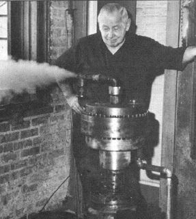
Karl Schaeffer was 67 years old when this reporter first interviewed him and photographed his demonstration in 1973. The story was not told sooner because Sonaqua Inc wanted the product fully developed before publicizing what they had.
The device is still not fully developed, but the story needs telling and our nation needs this new form of energy.
Karl Schaeffer found a way to harness some tremendous natural force which is inherent in molecules of water. There is no other way to state his principle.
"It all started for me when I was a graduating student of the trade-technical school in Berlin. The year was 1924", Schaeffer said in his thick German accent.
"I was in the washroom and when I turned off the water I heard the pipes knock", he said, referring to what engineers call "water hammer", a phenomenon in pipes that technology tries to eliminate.
"It was a loud knock and my mind suddenly said -- there is energy in that water hammer! And from that moment on, I was hooked."
"Of course I wondered if there was a way to harness such an energy, and I began my life-long quest -- well, it took me 50 years, but I have harnessed that energy and it can power the world.
"My machine can actually run forever so long as water continues to flow into it. Unlimited power! Free energy! Think of it!"
Karl Schaeffer was excused by his aides for "exaggeration". "Exaggeration my foot", Schaeffer bellowed. "I know what I have seen!"
The inventor had an unexplained engineering phenomenon occur four separate times during the years he was trying to perfect his device. He turned off the electric power to the motor, but the machine kept running until the water in the tank was gone.
Enough power sprang from within his mechanism to continue pouring forth steam from cold water and turn all the mechanical apparatus as well -- with the power off!
Those unexplained incidents led Schaeffer to make claims considered "wild" by other. But even if he was deluded, which does not appear to be the case, his machine is by far the most efficient means of making steam ever devised by man.
Karl Schaeffer did it the hard way -- but after coming to America from his native Germany and devoting all his time and a considerable family fortune to his "mechanical obsession", he finally harnessed that simple shock wave in water phenomenon.
"It appears that this device actually makes use of two principles engineers try to eliminate -- water hammer and cavitation", noted Dr. Tom Hunter, former professor of Mechanical Engineering at Illinois Institute of Technology when he watched a demonstration of the Schaeffer machine
"The force in the water is always there -- I have learned to use it, to intensify and use it", Schaeffer said emphatically.
One expert in engineering, chemistry and physics while watching the Schaeffer machine spin and spew forth steam said:
"I believe he is releasing energy that is inherent in molecules of water and this puts us on the verge of a totally new concept of energy utilization."
Essentially it is apparent that the vibrational and shock-wave nature of water can be used as a source of additional energy.
The Schaeffer machine is run by an electric motor that spins a metal disc. Cold water runs into the spinning flywheel where specially designed chambers cause an extremely rapid series of shocks to occur -- literally shocking the water into superheated steam.
Schaeffer demonstrated this energy conversion device in his machine shop on Belmont Avenue in Chicago for this reporter a number of times. The device was crude and inefficient next to some later models made by Bob Price of Sonaqua, but it was impressive nonetheless.
"You just watch what happens", the old man said proudly as he stepped up to his floor-mounted machinery. "You know how long it takes to boil water on your stove, don't you?"
I nodded that I understood a little about boilers, heaters and making steam.
"Feel this", he ordered and I put my hand on some pipes leading into the device from a water tank. It was cold -- tap water cold.
A 20-horsepower electric motor was mounted beneath the heavy metal rotary impeller. A pipe protruded from the opposite side of the disc and bent up and out a window.
Schaeffer pulled a switch and I witnessed an amazing energy conversion -- something totally new to the annals of engineering. The motor whirred and Schaeffer tinkered with a valve for about 20 seconds, then before half a minute had elapsed superheated steam spewed forth and cascaded out the window.
The outlet pipe was too hot to touch in a very short time, yet the inlet pipe continued to be as cold as the water running inside it.
Indeed, a 20-horsepower electric motor is an energy source, but later tests and more sophisticated equipment showed that the power out -- in the form of steam -- was greater than the power in from the electric outlet source -- an engineering impossibility, but a fact nonetheless!
In September of 1973, Sonaqua Inc took the Schaeffer device to the famed Battelle research institute in Columbus Ohio for efficiency tests.
The test results, submitted to George W. Moffitt Jr., board chairman of Sonaqua Inc on October 4, 1973 by L. J. Flanigan of the Nuclear and Flow Section of the Battelle, listed the efficiency of the device over eight test runs to be in a range between 97.3% and 99.0%.
An interesting aside to the formal report is that much of the experimentation was said to have been "not definitive because shortcomings in the experimental apparatus introduced large uncertainties into the results".
However, it was reported by Battelle personnel, that part of that same unexplained phenomenon reported by the inventor must have developed. An engineer told Bob Price, "We had readings in excess of 100% on several occasions, and that's not possible."
"I was told that one of the readings actually indicated an efficiency of 117%", Price said, trying to subdue a grin at the thought of the confusion such a development must have caused the engineers.
The Sonaqua people, especially Price, are careful to avoid any claims for the unexplained energy at this time. "We have the greatest efficiency and potentially the lowest cost apparatus for making steam there is", Price said.
Sonaqua did manage to sell a licensee the right to produce home heaters, only to find that after two years the licensee is having the same developmental problems faced by the parent company -- the new departure is up against dogmatic slide-rule skepticism and development money is hard to find.
Aquasonics of Denver has proven that a three-bedroom home with a basement can be comfortably heated with two small 3-horsepower motors.
"They have managed to heat a home with 20% less electricity than that used by a standard immersion unit, and they have had no trouble keeping the house warm -- excessively warm", Price said.
For two winters now a model house in the chilly mountain city has had more than adequate heat from the two small motors and the Schaeffer device.
Sonaqua is applying for grants to study exactly what it is that makes the shocked water heat up. Schaeffer's sons, Kurt and Karl, have worked with Bob Price and have designed some experiments to help discover precisely what takes place within their father's mechanical device.
Whether grants for such studies are forthcoming or not, it seems silly to have the use of the device withheld. There's no doubt that it works. Time enough to figure out why after it's in production and helping to curb America's excessive energy use.
Edison's light bulbs were giving light when electric theory was in its infancy. It's not necessary to know precisely what is going on in Schaeffer's machine -- the machine works consistently and that's what is needed.
Dr. Hunter, who viewed the device in action in this reporter's presence, said that it obviously performed in a wide range of efficiencies and eventually when the device was properly developed and finely tuned, the prospects were excellent for the product.
The professor of mechanical engineering did not care to comment on the "unexplained" part of the story.
Look at it this way. If the machine merely produces steam with a 98% efficiency (which Battell grants unequivocally), then it's the best thing for home use yet developed.
And there's no need for large hot water storage tanks as smaller storage units, heated more efficiently will suffice: no more need for pilot lights and natural gas.
In large apartment units there's no need for expensive boiler systems and either gas or coal fuel.
And if, when the skepticism is worn down and serious thought is given the device, the "unexplained phenomenon of the release of energy inherent in the molecules of water" is eventually proved and controlled, the world will have an alternative energy source that is sorely needed.

Steam Generator
Karl Schaeffer
February 12, 1974
US Cl. 122/11, 122/26
Intl. Cl. F22b 3/06
Abstract -- An apparatus and method for the production of steam and pressure by the internal creation of shock waves in a distended boy of water. The created shock waves are in the nature of water hammer and it is this water hammer which is repeated and intensified to such an extent the heat and pressure developed in the water converts the water into usable steam.
Background of the Invention
(1) Field of the Invention
Steam generators have been in use for many years. Such generators have primarily employed burnable fuels to raise the temperature of a body of water until the water changes into steam. The uses of steam generators have been many. Many building heating systems employ steam as the heating medium. Many chemical processes employ steam to produce certain chemical reactions. Come of these use the steam as a source of heat or to contribute to the reaction while others use the steam as a catalyst to promote the desired reactions. Many physical problems are aided by the use of live steam. For example, certain types of mining operations employ steam employ steam to expedite the removal of minerals from the ground. Also, in the drilling for petroleum and gas it is often desired to use live steam to cause the start of the upward discharge of these liquids and gases once pockets of them have been reached by drilling.
It is concluded that steam generators in the past have been useful and will continue to be useful in the future -- especially if a more economical steam generator is available. The steam generator of this present invetion is such an economical device.
(2) Description of the Prior Art
The use of water hammer for the generation of steam has just not been previously done to the best of our knowledge. However, physicists and engineers have long known of the existence of water hammer. Various books and texts have discussed water hammer and its attendant characteristics. Attention is directed to:
B.S. Massey: Mechanics of Fluids, Van Nos Rinhold, 1971 (pages 412 to 427).
John N. Bradley: Shock Waves in Chemistry & Physics;1962, Wiley, American Press, Metchuen, NY (pages 172 & 173).
Horace W. King: Handbook of Hydraulics, (4th Ed.), Revised by E. Brater; McGraw-Hill, NY, 1954 (pages 6-21 to 6-27).
A patent search has been made on the device as disclosed herein and this search has confirmed our belief that no one heretofore has conceived of such a device.
US Patent # 3,141,296 to Jacobs, Jr, et al., describes the utilization of shock waves produced in a liquid by an electric discharge to perform useful work. The shock waves are created by discharging electricity in a liquid-filled chamber and the useful work is defined as a pump for the liquid.
US Patent # 3,398,686 to Guin describes a motor which utilizes the power of shock waves created in a liquid by the discharge of electricity across a spark gap. Thus both Jacobs, Jr and Guin are very similar to each other and it is obvious that neither one produces shock waves in a body of liquid to produce an appreciable rise in temperature of that liquid. Also, neither one has created shock waves in a body of liquid by a mechanical means corresponding to water hammer to cause the temperature of that water to rise sufficiently to convert the water to steam.
Other steam generators having water chambers appearing similar to applicant's water chambers are Loefler, US Patent # 2,316,522, Gray, US Patent # 3,508,402, Reynolds, US Patent # 3,690,302. However, no one of these patented devices uses shock waves to cause the heating of the water -- rather, each one employs a combustible gas to effect a heating of the water for its conversion to steam. And, on close analysis each chamber is entirely different from applicant's chamber and lacking in the shock wave-generating mechanisms as subsequently defined in this specification/
Summary of the Invention
A principal object of the present invention is to provide a novel steam generator.
An important object of this invention is to provide a novel device to produce and intensify a series of water hammers within a distended body of water to thereupon substantially raise the temperature and pressure of such water.
Still another important object of this invention is to provide a device as set forth in the preceding object in which the water hammer is caused by alternating forces -- first a centrifugal action and second a vacuum action -- causing the body of water to be first pulled in one direction and then to snap back in an opposite direction.
Another and still further important object of this invention is to provide a device of the preceding two object in which the distended body of water includes at least one closed bottom passageway in which the movement of water therein is suddenly extinguished and in which the snapping back and forth action of the water column occurs to thereby intentionally impart a water hammer to the body of water so that a portion thereof is continuously converted to live steam.
Other and further important object and advantages will become apparent from the disclosures in the following specifications and accompanying drawings.
Drawings
Figure 1 is an elevational view of a preferred embodiment of the steam generator of this invention with portions thereof in cross section.

Figure 2 is a sectional view taken from the line 2-2 of Figure 1.

Figure 3 is a sectional view taken on the line 3-3 of Figure 1.

Figure 4 is a sectional view taken on line 4-4 of Figure 1.

Figure 5 is an elevational view of a modified embodiment of the invention and with portions thereof in cross section.

Figure 6 is a sectional view taken on the line 6-6 of Figure 5.
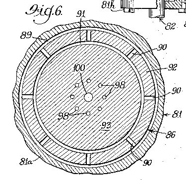
Figure 7 is a sectional view taken on the line 7-7 of Figure 5.

Figure 8 is a sectional view taken on the line 8-8 of Figure 5.

Explanation of the Drawings
The reference numeral 10 indicates generally the preferred embodiment of the steam generator of this invention. A stationary housing 11 encloses the steam generator 10, the housing comprises a main body portion 11a, an upper cap 11b fastened to the central body portion 11c, an under cap 11d fastened to the body portion 11a by a circularly arranged series of cap screws 11e, a downwardly projecting central tubular portion 11f forming a part of the under cap 11d, and a bottom cover 11e fastened by a series of circularly arranged cap screws 11h to the central tubular portion 11f.
A vertically disposed motor driven shaft 12 having an annular shoulder 13 therearound is journally carried within the central tubular portion 11f of the housing 11 by means of a roller bearing 14. The inner race of the bearing 14 is disposed between the annular shoulder 13 of the rotating shaft 12 at its top and the stationary cover 11g at its bottom. An annular seal 15 is held within the housing 12 to effect a sealing of the chamber above the seal from communication with the device below the seal.
A rotor designated generally by the numeral 16 is carried on and with the upper end of the motor driven shaft 12. The outer surface of the rotor 16 is cone shaped and is adapted to rotate within the outer housing 11. The housing and the rotor carried therewithin together define a generally distended chamber for the body of water which has its temperature and pressure materially raised by subjecting it to shock waves. A water inlet 17 is provided in the housing cap 11d and is the means for delivering water to the distended chamber within the housing 11 and in and around the rotor 16. The chamber is defined as distended because it is not just an open one-part chamber but rather is broken up into many small passageways which project in many directions. Webster's defines "distend" as "to stretch out or extend in more than one direction". The water body chamber includes a horizontally disposed ring-shaped passage 18 located between the housing under cap 11d and rotor 16. The rotor is vertically spaced above the housing on its underside to define the ring-shaped passage 18. The water inlet 17 directly communicates with the ring-shaped passageway 18 as best shown in Figure 1. An upwardly and outwardly flaring annular cone-shaped passageway 19 is located between the housing body portion 11a and the rotor 16. Again, there is a spacing between these elements to define the cone-shaped passageway 19. A plurality of radially inwardly extending arcuately spaced apart passageways 20 are adapted to pass through a portion of the rotor 16. At their outer ends these passages 20 join the cone-shaped passageway 19. An inwardly inclined conical shaped passageway 20 runs directly into the conical shaped passageway 21. This joining of the many passageways is shown in Figure 2. A radially inwardly extending ring-shaped passageway 22 is provided near the bottom of the rotor and joins the lower end of the conical shaped inner passageway 21. The inner end of the ring-shaped passageway 22 enters a vertically disposed central chamber of core 23 within the rotor 16.
The rotor 16 includes an outer cup-shaped portion 24 and a combination upper and top portion 15. This combination upper and top portion is fastened around its outer circumference by a plurality of arcuately spaced cap screws 26 to the outer body portion 24. The rotor 16 comprising comprising the two main parts is nevertheless a unitary device rotating as one mass. The two-piece construction permits the easy making of passageways 21 and 22 and before assembly permits the drilling of the plural passageways 20 near the top of the outer cup-shaped portion 24 of the rotor. Over the top of the rotating rotor there is defined a ring-shaped passageway 27 beneath the upper cap member 11b. A vertically disposed cylindrical ring-shaped passageway 27 has its top joining the top passageway 27 at the upper outside of the rotor 16. The outer periphery of a radially inwardly extending annular passageway 29 joins the lower end of the passageway 28 and at its inner periphery joins the upper end of the cone-shaped passageway 19.
A specially constructed fitting 30 has an externally threaded portion at its lower end at 31 which is threadedly engaged with internal threads within a central opening portion of the upper cap 116 of the housing 11. This fitting 30 forms the base for a superstructure 32 disposed over the basic unit contained within the housing 11. Of course, the superstructure then comes an extension of the stationary housing 11. An outer pipe 33 has its lower end threadingly engaging the upper end of the special fitting 30 at 34. A special cap fitting 35 threadingly engages the upper end of the outer pipe 33 as shown at 36. An inner concentric pipe 37 and a radially inwardly projecting annular flange 38 of the cap fitting 35 are joined to one another by a threaded engagement as shown at 39. The juncture 39 is located at an intermediate position between the top and bottom of the vertically disposed inner concentric pipe 37.
An adjustable value 40 is provided on the top of the inner pipe 37 to control the discharge of steam as the steam is generated in the device of this invention. The valve 40 is threadingly engaged at 41 to the pipe 37.
The lower end 42 of the inner pipe 37 has its outer surface milled or turned down so the pipe wall is relatively thin and thus may be assembled with the other concentric members by passing downwardly through the internal threads on the annular flange 38. An intermediate concentric pipe 43 has its upper end disposed between the cap fitting 35 and the inner pipe 37. The upper end of the intermediate pipe 43 stops short of contact with the underside of the flange 38, leaving a space 44 thereover.
An annular flange 45 is provided intermediate the top and bottom of the special fitting 30. External threads are provided on the intermediate pipe 43 near its bottom and these threads cooperatively engage with internal threads on the inner aperture of the special fitting flange 45 as shown at 46. The pipe 43 includes a lower extension 47 which has its surface milled or turned down to permit it to pass by the threads 46 on the flange 45 during assembly. This is similar to the turning down of the lower extension of the inner pipe 37.
The intermediate inwardly extending annular flange 45 of the fitting 30 is provided with a plurality of arcuately spaced apart vertically disposed holes 48. These holes constitute restricted passageways of the water in the steam generator of this invention from the lower chamber 49 defined by the fitting 30 to an upper portion or chamber 50 as defined above the annular flange 45 and between the intermediate pipe 43 and the outer pipe 33. The upper limits of the chamber 50 are defined by the inner and underside of the special cap fitting 35.
A thin annular chamber 51 is disposed between the cap 35 and the intermediate pipe 43. A second thin elongated chamber 52 is concentric with the chamber 51 and is located between the intermediate pipe 43 and the lower end 42 of the inner concentric pipe 37. By reason of the space 44 over the top of the intermediate pipe 43 the thin annular chambers 51 and 52 are joined one to the other. The elongated annular passageway 52 is provided with an annular opening 53 located at the bottom of the lower extension 42 of the inner concentric pipe 37. A central passageway 54 is provided within the inner pipe 37 and is utilized to carry generated steam to the controlling valve 40 at the top thereof.
Operation of the Device of Figure 1
To commence operation, water under normal line pressures is admitted to the inlet pipe or fitting 17 so that water flows in the direction of the arrow 55 to the distended or tortuous path chamber which comprises a single body of water. The arrow 56 shows movement of water form the inlet 17 through the annular passageway 18 and to the cone-shaped passageway 19 where the water proceeds upwardly in the direction of the arrow 57. From there the water enters the several radial holes 20 and moves in the direction of the arrow 58 to the inner cones-shaped passageway 21 where the water moves downwardly in the direction of the arrow 59. The passageway 21 is joined at its bottom to the annular ring-shaped passageway 22 and as shown by the arrow 60 water moves radially inwardly to the central passage 23 within the rotor 16. The water then proceeds upwardly as upwardly as indicated by the arrow 61. Here the water enters the special fitting lower chamber 49 and as indicated by the arrow 63 moves upwardly therethrough into the restricted apertures 48 and continues upwardly through such vertically disposed apertures as indicated by the arrows 64. The upper end of the chamber 50 joins the thin annular ring shaped chamber 51 and as indicated the water moves further upwardly in the direction of the arrows 65 to the space 44 just beneath the annular flange 38 of the special cap 35. Now the water changes its direction of flow and starts moving down and through the thin annular ring-shaped chamber 52 in the direction of the arrows 66. In addition to the water moving vertically into the chamber 62 a portion thereof moves radially outward through the passageway 27 in the direction of the arrows 67. At the outer end of the ring-shaped passageway the water moves down the vertical ring-shaped annular passageway 28 in the direction of the arrow 68. Now the water travels radially inwardly through the ring-shaped horizontally disposed annular passageway 29 in the direction of the arrow 69 and hence back to the outer conical shaped passageway 19 between the rotor 16 and the main body portion 11a of the housing 11.
Water now fills the entire distended chamber which as explained contains numerous passageways forming a tortuous path and providing a cycle for the movement of water therethrough. Prior to the complete filling of the system with water, rotation of the shaft is commenced. The shaft 12 is rotated by coupling a motor thereto and the rotor 16 with its several unitary parts 24, 25, and 26 is rotated at a relatively high speed causing the water to be thrown centrifugally outwardly within the chamber through any passageway thereof having a radial disposition or a radial component. The large horizontally disposed ring-shaped annular passageway 27 is one such radial passageway. This immediately results in the water being drawn downwardly out of the closed bottom passageway comprising the chamber and passageways 49, 50, 51 and 52. The water suddenly and positively pulled downwardly from this closed bottom channel creates a vacuum in the bottom of this channel which in the device of Figure 1 is at the top of the stationary superstructure at the space 44. This newly created vacuum now sets up a pull of its own which exceed and overcomes the centrifugal forces and the body of water comes back into the bottom of the closed bottom channel with a snapping action. This sudden striking of the closed bottom extinguishes movement of the column of water and there is a substantial shock imparted to and within the body of water. This water hammer or shock brings with it a rise in pressure and temperature of the body of liquid. In Horace King's book "Handbook of Hydraulics" published by McGraw-Hill (4th Ed., pp. 6-21) there is a discussion of water hammer and its creation. The King handbook states that if a passageway in a pipe line is suddenly closed (corresponding to the closed bottom channel in the applicant's device), "a dynamic pressure, I addition to the normal static pressure, is created within the pipe. This dynamic pressure is commonly called water hammer. It is caused by the sudden transformation of kinetic energy to pressure energy".
J. N. Bradley's Shockwaves in Chemistry & Physics discusses "The Measurement of Thermodynamic Quantities" in Chapter V, p. 172 of that book and states:
"A shock wave in a liquid medium is characterized by a small rise in temperature and an extremely large change in pressure."
Applicant is thus intentionally creating shock waves in this distended body of water causing both temperature and pressure rises. Although the temperature rise created by each shock is small, the shocks are repeated over and over again, one upon the another, and thereby intensified causing a material rise in temperature of the entire body of water. Each shock caused by the sudden extinguishment of flow of water at the dead-ended channels creates a force of approximately 63.4 pounds per square inch of every foot of extinguished velocity. Although this degree of pressure is only held momentarily, the succeeding shock waves are cumulative and although the pressure dissipates throughout the body of water the temperature rises materially and is not so easily dissipated as the pressure. The rise in temperature and the maintenance of that temperature rise is so spectacular that steam is almost instantly created and starts up the pipe 37 through its center passage 54 in the direction of the arrows 70. Unconverted steam in the form of water in various stages of heat is pulled downwardly in the direction of the arrows 71 whereupon the cycle is repeated with the rapidly increasing shock waves causing the water to be more easily converted into steam and that steam being discharged upwardly in the direction of the arrows 70 and thence through the adjustable valve 40. Of course, water is always being admitted to the inlet 17 to keep the system full and constantly replenish that portion of the water that has been converted to steam and has been discharged through the valve 40 for some external use.
The modified or alternative construction of Figure 5 is similar to the preferred device of Figure 1, but is shown primarily to emphasize that various body chambers may be employed. As explained for the device of Figure 1 the water chamber is distended in nature -- not any particular shape -- but expressly including one or more closed bottom channels within which a vacuum may be drawn and at least one or more radial passages or passages with radial components to produce a centrifugal action. The steam generator of Figure 5 is generally designated by the numeral 80. The generator is provided with a stationary housing 81. The housing comprises a main body portion 81a, an upper cap 81b fastened to the central body portion 81a by a circularly arranged series of arcuately spaced apart cap screws 81c, an under cap 81d fastened to the body portion 81a by a circularly arranged series of arcuately spaced apart cap screws 81e, a downwardly projecting central tubular portion 81f forming a part of the under cap 81d, and a bottom cover 81g fastened by a series of circularly arranged arcuately spaced apart cap screws 81h to the central tubular portion 81f.
A vertically disposed motor driven shaft 82 having an annular shoulder 83 therearound is journally carried within the central tubular portion 81f of the housing 81 by means of a roller bearing 84. The inner race of the bearing 84is disposed in a vertical position between the annular shoulder 83 of the rotating shaft 82 at its top and the stationary cover 81g at its bottom. An annular seal 85 is held within the housing 82 and brushes against the rotating shaft 82 to effect a sealing of the chamber above the seal from communication with the device below the seal.
A rotor, conical in shape, is designated generally by the numeral 86. The rotor is carried on and with the upper end of the motor driven shaft 82. The rotor 86 is adapted to rotate within the outer housing 81. The housing and the rotor carried therewithin together define a generally distended chamber for the body of water which has its temperature and pressure materially raised by subjecting it to shock waves. A water inlet 87 is provided in the housing cap 81d and is the means for delivering water which has its temperature and pressure materially raised by subjecting it to shock waves. A water inlet 87 is provided in the housing cap 81d and is the means for delivering water to the distended chamber within the housing 81 and in and around the rotor 86. The chamber is defined as distended for the same reasons as applied to the chamber of the device in Figure 1. The water body chamber also includes a horizontally disposed ring-shaped annular passage 88. The rotor is vertically spaced above the housing on its underside to define the ring-shaped annular passage 88. The water inlet 87 directly communicates with the ring-shaped passageway 88 as best shown in Figure 5. An upwardly and outwardly flaring annular cone shaped passageway 89 is located in the space between the housing body portion 81a and the rotor 86. A plurality of radially inwardly extending arcuately spaced apart passageways 90 are adapted to pass through a portion of the rotor 86.At their outer ends these hole-like passages 90 join the cone-shaped passageway 89. An upwardly inclined conical shaped passageway 91 is concentrically disposed radially inwardly of the conical shaped passageway 89.The inner ends of each of the plurality of horizontal passageways 90 run directly into the conical passageway 91. This joining of the many passageways is shown in Figure 5 and further in the sectional view of Figure 6. The inner cone shaped passageway 91 forms one of the closed bottom passageways of this distended chamber of the device of Figure 5.
The rotor 86 includes an outer cup-shaped member 92, an intermediate member 93 generally nesting within the cup portion 92 and a circular or disc-shaped cap member 94. A plurality of arcuately spaced apart cap screws 95 define an outer ring around the cap 94 and constitute the means of joining the cap 94 to the outer portion 92 of the rotor 86. A plurality of similar arcuately spaced apart cap screws 96 define an inner ring around the cap 94 to the intermediate portion 93 of the rotor 86.these three body members with their cap screws 95 and 96 together constitute a unitary rotor which rotates within the stationary housing 81 and thereby crates the shock waves for effecting the rise in the temperature of the distended body of water to generate steam.
The rotor 86 includes an annular ring shaped passage 97 disposed between the intermediate portion 93 and the cap 94. The top of the outer annular portion of the intermediate portion 93 is milled or turned down to provide the space for the annular passageway 97. The rotor also includes a plurality of arcuately spaced apart vertically disposed closed bottom channels 98. The arrangement of these holes or channels 98 is in a circular path which is generally arranged concentric to the center of the composite rotor. The inner annular surface 99 of the top of the intermediate portion of the rotor has not been milled down and thus having its full height abuts the underside of the cap 94. Thus when the cap screws 96 are drawn up tightly the unmilled central ring portion 99 of the member 93 acts as a spacer for the remainder of the top of that member from the underside of the cap 94. This clearly defines the radial passageway 97 which joins the inner cone shaped passageway 91 with the open topped closed bottom holes 98. The rotor is further provided with a central vertically disposed passageway 100 about its vertical centerline. At the juncture of the bottom center of the intermediate member 93 of the rotor with the bottom of the cup-shaped outer member 92 of the rotor the central passageway 100 is enlarged as shown at 101. A plurality of relatively small diameter radially disposed holes or passageways 102 join each of said closed bottom channels 98 with the enlarged chamber 101 at the center of the rotor. These radial passageways 102 are disposed at a position spaced above the closed bottoms of the holes 98. It is generally through these minute relief holes 102 that generated steam is permitted access to the center of the rotor where it moves upwardly through the passage 100 and thence into an enlarged steam passageway 103 located above the channel 100. Steam may be permitted free escape from this passageway 103 or may be selectively discharged by a suitable adjustable valve means such as that shown at 40 in Figure 1.
Operation of the Device of Figure 5
As for the steam generator of Figure 1 water is admitted to the system of Figure 5 by passing through the inlet 87 in the direction of the arrows 104. The water then moves in the annular ring-shaped passageway 88 in the direction of the arrows 105 to the juncture with the cone-shaped passageway 89. the water now moves upwardly in the direction of the arrows 106 to the juncture of the full annular passageway 89 with the plural radial passages 90. Water then moves inwardly in the direction of the arrows 107. As previously stated, an inner concentric cone-shaped passageway 91 joins these several radial holes 90 and thus the incoming water fills that passageway as shown by the arrows 108. As the ring-shaped bottom of the passage 91 is effectively closed the water then moves radially inwardly across the top of the outer portion of the intermediate member 93 of the rotor in the passageway 97 as shown by the arrows 110 to thus fill the entire distended chamber formed by this maze of multi-directional passageways. Most of the arrows just described for the movement of water in the various chambers and passageways are two headed indicating that water during the operation of the device moves in both directions.
Prior to the system being completely filled with water, rotational drive is imparted to the shaft 82 and thereupon its integral rotor 89 is also rotated. Rotation is at relatively high speeds. The initial response to the body of water is its centrifugal action through all radial passageways and passageways having radial components. In this device the primary centrifugal action is created in the elongated radially outwardly extending annular ring shaped horizontally disposed passageway 97. The imposition of this force in the body of water causes the columns of water in the multiple closed ended channels 98 within the rotor to be drawn upwardly out of their closed bottoms.
Almost immediately there is a multiplicity of vacuums created in each closed bottom with the result that the vacuum overcome and exceed the opposite force of centrifugal action to thereby cause the columns of water to snap back into the closed bottoms of these channels. As previously explained for the operation of the device of Figure 1 the extinguishment of the motion of the body of water by the closed bottoms of the channels imposes shock waves in the distended body of water so that there is an incremental increase in both the temperature and pressure of the body of water. The repeated and continuous rotation of the rotor causes multiple shock waves or water hammer and actually an intensification of the shocks when they are occasioned one upon the other. Thus what would have been only a small rise in temperature is now substantial. The pressures similarly rise but they quickly dissipate in the system. The water commences its conversion to steam generally in the area of the closed bottoms of the channels 98 where the greatest effect of the snap action shocks takes place. This newly created steam is permitted to escape radially inwardly through the restricted holes 102 in the direction of the arrows 111. Once in the central chambers of the rotor the steam moves vertically upward through the successive passages 101, 100 and 13 as indicated by the arrows 112.
Both the devices of Figures 1 and 2 act to generate steam. Their common attributes are their stationary housings with rotors therein which together define distended chambers with tortuous passageways and at least one closed bottom passageway and a passageway permitting centrifugal action to create forces in the body of water opposite to the vacuum created forces in the body of water opposite to the vacuum created forces in the closed bottom channels. In Figure 1 the closed bottom channel is located in the stationary housing portion of the device whereas in Figure 5 the closed bottom channels are located in the moving rotor. It is thus apparent that the steam generator of this invention may take many and varied forms without departing from the principles disclosed herein. Thus it is not my intention to limit the patent granted herein otherwise than as necessitated by the appended claims.
Infinite Energy (July-August 1995, p. 30)
"Other Cavitation Reports: The Schaeffer Steam Generator"
by
Michael Huffman
…I have two reports done by two university professors on two different versions of the Aqua machine.
As some of you may know, Carl Schaeffer patented his device in 1973. He reportedly spent about $5 million developing and marketing the device. He faced a great deal of resistance from the academic community, and was never able to commercially manufacture the device. He ended up selling the patent for the device in 1988 to the Aqua Corporation in Chicago for $1, shortly before he died. Bob Price was an engineer who had worked with Schaeffer on the device for 12 years. He has his own machine shop and was able to design, build and test his own prototypes.
He went to the Aqua Corporation and together they spent an additional $500,000 developing and attempting to market the device. Again, they faces a great deal of skepticism, and were unable to successfully market the device. Their main problem was, however, that they were asking $50 million for a technology that would become public domain in a couple of years. Grant Stouffle was the CEO of ill-fated Aqua, Inc., and in my opinion, not a very realistic businessman. Even though they got some serious multi-million dollar offers from some large capitalization, international corporations, Grant believed that the technology was worth more than that, and managed to convince the stockholders that they should hold out for more money.
When Bob Price's wife died, he left Aqua Inc to live with his family in another state. Sheldon Hughes joined the Aqua Corporation as an engineer in 1990, and helped develop the device further. He didn't have a machine shop, and the Aqua Corporation ended up spending between 10 and 50 thousand dollars per unit to have them made. Sheldon was working on a deal with the Swenson Corporation, a manufacturer of multi-effect evaporators, to make and test prototypes. That was where AI first saw the machine that I reported on in the March/April edition of Infinite Energy. The Aqua Corp ended up running out of money shortly after that, and no more prototypes were ever built. The Aqua Corp then formally folded.
The first report that I have from the Aqua Corp was titled, "Preliminary Report on Aqua Inc Rotary Impeller Water Heater". It was written by Linda McDonald, chairman of the Dept. of Physics, North Park College, IL (May 5, 1989). The report s very much like Scott Little's report on the Yusmar. The report is 9 pages long. There is an introduction which defines the variables and formulae, a description of the physical characteristics of the apparatus, a description of the testing procedure and instrumentation, a page of data collected from the 10 test runs performed in three temperature ranges, a conclusion section, and an appendix.
The machine that was tested was one of Bob Price's variations of the Schaeffer device. The test procedure used was also very similar to Scott's. It was a basic barrel calorimetry type test in which the incoming water temperature was measured against the elevated outgoing water temperature, the volume of water, the power consumption, and the time were measured. In the error analysis section, the accuracy of the measurements was calculated to be +/- 11%. No mention at all was made of the efficiency of the motor or any motor-related heat losses. The table of data reported explicitly that the efficiency of the device was between 1.09 and 1.30, depending on the output temperature of the run. The operating temperatures ranged from 97° F to157° F. The lower temperatures gave the higher efficiencies.
The other university test report is titled "Aqua Motor Tests" by the Institute for Aviation Research, Wichita State University, KS, and was written by Glen W. Zumwalt, PhD, Professor of Aerospace Engineering, dated March 8, 1990. The tests were performed on several of Sheldon's designs. The report is 8 pages long. Much of the same format is used for the report, with the addition of two diagrams of the test bed configuration. The data collected and the formulae sued were described in even greater detail than the McDonald report. In this report, a paragraph is devoted to the observation of "blue steam" [Exactly what James Griggs sees with his machine. - Ed., Inf. En]. The testers speculated that the coloration may have been due to the boiling of the grease in the shaft seal. Samples were collected and analyzed with a gas chromatograph, but only pure water was found. They concluded that the coloration remained a mystery.
The issue of efficiency was treated in a very interesting manner, however. In this report, at the end of the data tables for each test run, there is the statement, "If the electric motor efficiency is XX.X%, shaft power supplied equals the heat produced". The efficiency numbers used varied with the different rotor designs, but some of the numbers exceeded the manufacturer's nameplate efficiency rating, which led to the recommendation by Prof. Zumwalt that a dynamometer be used in future tests to verify the data collected in the barrel calorimetry tests.
The test performed on the "Griggs gadget" by the Emprise Corp report an efficiency of 120% for hot water runs, and 140% for steam runs. This report was written by R.A. Dubose, President of the Emprise Corp on February 16, 1994. Again, this report relied on the motor manufacturer's nameplate efficiency rating in its' calculations, and recommended that a dynamometer be installed in the test bed to verify the data collected and reported.
The test procedure was the barrel calorimetry type of test that Jed Rothwell and Gene Mallove described in their reports. Sheldon also wrote a couple of reports to the Aqua Corp shareholders on the tests performed at the Swenson Corp testing facility. One report is 4 pages long, and the other is 3 pages. Sheldon measured the amount of steam collected, and found that it was far greater than his device than with an electric boiler. These reports include graphs that plot the horsepower used against the steam value output. Depending on the amount of horsepower used, the amount of steam collected was 250% to 500% more than an equivalent powered resistance coil boiler system. The minutes of the Aqua Corp stockholder meetings show that they voted to have Sheldon patent his design, but Sheldon said that they never gave him the money to do it. As a result, he never patented any of the designs that he came up with while working with the Aqua Corp.
As you can see from all these reports done by some fairly well qualified individuals, mostly in laboratory settings, these devices demonstrate overunity efficiency.
I just got a packet of information from my dad containing more information about the devices developed by Aqua Inc and Sonaqua Inc. The first report was made by Raymond E. Ross, and I believe he was a principal of Sonaqua Inc of Colorado. The report is not dated, but the note at the bottom from my father suggests that Aquasonics had purchased a license form Sonaqua Inc (the original Schaeffer corporation) to develop and market the Schaeffer device. The note further explains that Aquasonics failed to live up to the contract, went bankrupt, and lost its license. The Colorado based company was marketing the device as a home heating system, and was calling it the "Delta Tee".
Evidently, Raymond Ross installed one of these devices in his home, and took measurements of the performance. There is no description of the device, the testing protocols, or instrumentation used to make his claims. The report was simply a statement, according to my father's note, and a set of preliminary data that was recorded before sending the device to the Battelle Institute in Columbus OH for testing in their lab.
It was not a formal report. I would call it more of a testimonial that a scientific report, but it does have some very interesting things to say. The report made by the Battelle Institute was not included in the packet. It was supposedly a formal report of over-unity performance that was the result of testing done at the Battelle Institute. According to Bob Price Aquasonics supposedly paid $40,000 to Battelle Institute to perform these tests. The following is the complete report from Aquasonics, Inc.:
The Aquasonics Delta-Tee ~
In m opinion, the conventional way of estimating BTU output (GPM x delta-T) cannot be used for our unit. I think we have proved this at the Ross residence in Broomfield. By the conventional way of estimating BTU output, we are heating a 1440 sq. ft. house with a full basement, or a total of 2880 sq. ft. to 75° F. with the outside temperature of 0° F with less than 20,000 BTU/hour.
A separate test was made with immersion-type electric heaters. All engineers agree that this way of heating water is as close to 100% efficiency as you can get. Two 4.5 kilowatt immersion units were used in the same tank and through the same piping (two 4.5 kw immersion units = 30,708 BTUH). This 100% efficient water heater could not heat the house above 66° F when the outside temperature was 15° F. A fire had to be built in the fireplace to keep the house warm. The Aquasonics Delta Tee unit did a better job for 10% less cost. I think a good way to test the BTU output would be to build a 20' x 20' refrigerated cooler (like a meat cooler) and inside of this build a small house. This way we could have a controlled environment and measure the air temperature inside the house. In the past year we have tried almost every type of thermometer that is on the market and we can't believe the readings we get, nor could we get anyone else to believe them. With some of the readings we got, the unit showed as high as 700% efficiency. Several of the best engineers in the country tried to prove us wrong and couldn't. May time the water temperature at the unit would read 150° F, run through 100 ft of 3/5" baseboard radiator and return to the unit at 152° F, a gain of 2 ° F after running through 100 ft of radiator and giving off heat. This is impossible. It is also impossible to heat 2,880 sq ft of floor space with two 3-hp motors that equal 13,200 BTUH, but the Aquasonics Delta-Tee does the job and does it well.
Report made by Raymond E. Ross [Signature]
The second page of the report is a piece of paper with the hand written results of 10 test runs. The average efficiency was 96%, not taking into account the benefit of the inefficiency of motors. There was no mention of the formulae sued to come up with these numbers.
Cribbed from Bill Beaty @ http://www.eskimo.com:
From:
mdudley@brbbs.brbbs.com (Marshall Dudley)
Subject: Another theory for Griggs device
Date: Sat, 17 Dec 1994 12:14 -0500 (EST)
In a previous post I hinted at another possibility of what may be happening in the Griggs device when I mentioned "non-linearities in the steam table" as one of several things that should be looked at. Since I did not get any bites on that, let me outline a discussion I had with a scientist from Oak Ridge National Labs about the Griggs device several months ago. This discussion is off the record, and most likely will not be collaborated, just as some of the results of their CF cell experiments are.
I had an occasion to meet with this person and begun describing the Griggs device to him. After telling him how it worked I ended it with, "and it is reported to produce more steam or hot water than then the input power should produce". His response was "that's not surprising". I was almost floored.
He then told me that is a fairly well known fact among some researchers that the published steam tables are wrong. The original team which made up the steam tables found that toward the extremes (high pressure high temperature and low pressure and temperature) there are unexplained non-linearities. Since these non-linearities could not be explained, and were shown to not obey the conservation of energy, they fudged the tables to get rid of the non-linearities. They had assumed that there must be an error in their measurements or equipment since it did not jive with theory. Since then others have found the same thing, but none of them will stick their neck out to declare that steam tables which have been in use for decades are wrong, especially since there seems to be no theory to explain these non-linearities. Anyway, he said that if you go through a cycle of vaporization at one pressure and condensation at a higher pressure and temperature, when you get back to the original temperature and pressure the "corrected" steam table does not close. That is to say, according to the measurements there is steam left over which should not be there, and by conservation of energy cannot be there. Anyway, he said that it seems that such a device such as Griggs would enhance this non-linearity effect and therefore produce more energy than is supplied. He does not have the foggiest idea where the excess energy could come from, but simply that given what he knows about the non-linearities in the (corrected) steam tables, that seems like a good place to start looking. I find the idea intriguing, but as with so many other theories, it leaves one with as many questions as it gives answers.