Wilhelm
SCHMIDT
Undulatory Propulsion
Undulatory Propulsion

 Wilhelm SCHMIDT
 Science & Teknologie ( 1970 )

GB 916667
Improvements in or relating to propulsion means for vehicles for movement on land, water or in the air
Improvements in or relating to propulsion means for vehicles for movement on land, water or in the air
1963-01-23
Inventor(s): SCHMIDT WILHELM
Applicant(s): FORSCHUNGSZENTRUM DER LUFTFAHR
Classification: - international: B62D57/04; B64C23/00 - European: B62D57/04; B64C23/00AIDT
Abstract -- A vehicle is propelled by generating a stream of flowing medium, which is deflected by flow diverting means consecutively on to different sides, including two opposite sides, of a body extending in the direction of propulsion. In Fig. 1, a stream of moving fluid 1 generated by an air screw or water screw 2 is directed over a flap 4 oscillated about an axis 3, so that the stream is deflected to impinge alternately on to the opposite faces of a streamlined body 5. This is stated to allow a reduction in the difference between the velocity of the generated stream and the velocity of the surrounding medium, both relatively to the vehicle, resulting in improved thrust and less noise generation. The flap 4 is driven from a shaft 7 through suitable gearing 8 and an electromagnetic slipping clutch 10 controlled by a potentiometer 11. In Fig. 2 the fluid stream passes through a hollow twin shelled body 12, the part of the flow within the annular space 15 being cyclically controlled by revolving shutters 19, 20, to issue alternately through inwardly directed slot nozzles 17, 18 and thus deflect the main flow through the body in alternate directions. Valves 21 control the flow through space 15, and the speed of revolution of the shutters 19, 20 is controlled by gearing 22. In a further embodiment, the flow is divided wholly between two nozzles, each directing the flow on to one face of body 5, and the nozzles are closed cyclically. There may be more than two nozzle, the body 5 then being pear shaped. In another embodiment, the fluid stream is electrically charged or inoculated with charged particles and deflected by an alternating electric or magnetic field. In, Fig. 6, the tail pipe 32 of a jet propulsion engine contains a deflecting element comprising a bullet 33 and eccentric portion 34, which are rotated by a furbine shaft 27 through epicyclic gearing 39. A similar rotating deflector may be used in a slipstream casing downstream of a propeller. The deflector is movable axially for control purposes by a linkage 38. The tail pipe may be surrounded by a duct 35 also conveying the fluid stream. The pipe 32 and deflector 34 may then rotate together. The tail pipe may have an eccentric nozzle instead of the deflector and be rotated. The downstream ends of pipes 32 and 35 may comprise displaceable overlapping plates for varying the outlet areas. The body 5 may comprise members 44, 45 which are adjustable to deflect the fluid flow.
COMPLETE SPECIFICATION
We, FORSCHUNGSZENTRUM DER LUFTFAHRTINDUSTRIE, Landstrabe, Konigsbrucker, N 2 Dresden, Eastern Germany, a nationalised corporation organised and existing under the laws of Eastern Germany, do hereby declare the invention for which we pray that a patent may be granted to us and the method by which it is to be performed, to be particularly described in and by the following statement: -
The invention relates to propulsion means for vehicles whether for movement over land, water or in the air, in which the thrust of a generated stream of flowing medium is utilised to propel the vehicle.
A stream of flowing medium which is utilised for the purpose of imparting forward thrust may take the form, for instance, of the propeller slipstream of an aircraft, the jet issuing from the tail pipe of aircraft and rocket jet propulsion units, and the race of the screw of a ship The forward thrust is produced by the velocity differential of the streaming medium over the speed of travel of the vehicle It is known that this thrust is the greater the larger the cross section of flow and the higher the velocity differential On the other hand, the efficiency of the process is better the smaller the velocity differential, i e the closer the velocity of the streaming medium approaches the velocity of travel or flight To obtain a high thrust and at the same time a satisfactory efficiency it has hitherto been the practice as far as possible to enlarge the cross section of flow and to reduce the velocity differential to the minimum possible However, in many cases, the maximum possible cross section of flow is reached before satisfactory efficiencies 40) are obtained. Obviously this will apply to a ship in shallow waters and to a propeller driven sledge. Moreover, limits are imposed in the case of propeller-driven aircraft by the fact that efficiency falls when the tips of the airscrew reach sonic velocity In jet 45 propelled aircraft technical and structural reasons also impose limits upon the maximum possible cross section of the jet, and the efficiency of such plant is still substantially lower than that of aircraft driven by 50 propellers.
Apart from efficiency, the development of noise likewise depends upon the velocity differential The noise becomes greater as the velocity differential increases and this is an 55 other reason for keeping the velocity differential at as low a value as possible.
The object envisaged by the invention is to improve the propulsion means in craft in which a flowing stream of medium is gener 60 ated to provide forward thrust, by substantially reducing the velocity differential below that which was hitherto possible without reducing the thrust and without being dependent upon an increase in the cross section of the 65 propulsive stream.
The solution offered by the invention consists in exploiting the Knoller-Betz effect otherwise known as the Katzmeyr effect, which may be likened to the principle in 70 volved in the development thrust by the flapping of wings in the flight of birds.
The present invention provides propulsion means for vehicles in which the thrust of a generated stream of flowing medium is 75 employed to propel the vehicle, characterized in that the straight initial stream of medium is deflected, by means which change the direction of flow, consecutively upon different sides of a body extending in, or approximately in, 80 the direction of propulsion, and at least upon two opposite sides of such a body.
The invention will be more particularly described by reference to the accompanying drawings.
Figure 1 is a perspective view of propulsion means according to the present invention wherein deflection of the streaming medium is effected by means of body which is hingeably moved to and fro,

Figures 2 and 3 are a perspective view and a side elevation respectively, showing the medium deflected by flow pulses,

Figure 4 is a side elevation showing the medium deflected by means of an electric field, and
Figures 5 and 6 are side elevations showing the medium deflected by revolving deflector bodies.


These drawings show the manner whereby the streaming medium is deflected on to the longitudinal sides of the impingement body, said deflection being effected in Fig 1 by means of a body which is hingeably moved to and fro, in Figs 2 and 3 by flow pulses, in Fig 4 by means of an electric field, and in Figs 5 and 6 by revolving deflector bodies.
In Fig 1 the stream 1 is generated by a propeller 2 This stream is alternately deflected by a body 4 which flaps up and down about an axis 3 alternately on to the so upper and lower side of a profiled aerodynamically cross-sectioned body 5 The angle of incidence of the current in relation to the direction of forward thrust is therefore alternately greater and smaller than 00.
To raise and lower the deflecting body 4 alternation gear means 8 of known kind are actuated by shaft 7 provided for transforming the rotary motion of shaft 7 into an up and down flapping motion of body 4, as indicated by arrow 9 To control the frequency of reversal of body 4 a regulating element 10 is provided, for instance in the form of an electromagnetic clutch incorporated in shaft 7, of which the slippage can be controlled by a variable resistor 11 Instead of being thus pivotally deflected, body 4 may be oscillated at least approximately perpendicularly to the direction of flow for instance by means of a suitable crank motion, the frequency of oscillation being likewise controllable.
In Fig 2 the stream 1 which passes for instance through a hollow body 12 is deflected alternately upon the upper and lower face of an aerofoil S by the impingement of supplementary flow pulses 13 and 14 The angle of incidence of the pulses in relation to the principal stream is greater than 00 and less than 90 The hollow body 12 may be in the form of a twin shell and the space between the shells may then be used to conduct an additional stream 16, this latter stream 16 being allowed to emerge at the outlet end alternately from two opposite slots 17 and 18 controlled by revolving coupled shutters 19 and 20, as indicated by dotted lines Conveniently the stream 16 inside the space 15 may be controlled, for instance, by adjustable flaps 21 and the speed of revolution of the shutters 19 and 20, for instance, by a controllably variable gearing 22 which is only schematically indicated If required, the direction of the pulsed flow 13 and 14 may be arranged to be controlled by the appropriate adjustment of the outlet ends of hollow body 12.
In Fig 3 the upper and lower faces of the aerofoil 5 are alternately exposed to a stream emerging from two outlet nozzles 23 and 24 which are inclined towards these two faces The total stream may be divided between these two outlet nozzles 23 and 24 and, since the medium is to impinge upon the two faces of the aerofoil 5 in alternation, each nozzle may be closed in predetermined rhythm by appropriate shutter means On the other hand, each of the outlet nozzles may be associated with a jet engine of its own and the two jet engines may be arranged to fire alternately If the jet engines supply a transonic or supersonic stream the outlet nozzles may be located parallel with the longitudinal axis of the aerofoil with obliquely cut ends in such manner that the planes of the two sections are inclined towards opposite sides of the aerofoil An alternative possibility consists in providing more than two outlet nozzles of the said kind and to provide a pear-shaped impingement body in such manner that its peripheral surface will be exposed on different sides in alternation or in succession to the streams emerging from the several nozzles In such form of construction it is likewise preferred to provide means for controlling the magnitude of flow and/or its angle of incidence with respect to the impingement body 5 and/or the frequency of the pulses.
Another possibility is schematically illustrated in Fig 4 and consists in electrically charging the flowing medium 1 and/or inoculating the same with charged particles and in then deflecting the same by exposing it to a rhythmically fluctuating electrical field on to at least two opposite faces of an impingement body 5 It is expedient to provide means for controlling the voltage and/or frequency employed for generating the electrical field Moreover, in appropriate circumstances an electromagnetic field may be employed instead of an electrical field.
Fig 5 illustrates a deflecting body 26 mounted on a shaft 27 indicated in dotted lines and rotated by suitable drive means.
The stream 1 of medium utilised for imparting forward thrust to the craft is in the illustrated example generated by a rotating propeller 28 The stream 1 is deflected by face 29 of the rotating deflector 26 in such a way that it will impinge upon the sides 916,667 flow prior to its deflection, and in which the shape of the deflector is such that it will block or open at least one roughly sectorial or segmental portion in at least one part of the internal circular section of the hollow body 32 It will then be advisable to provide the deflector 26 with a substantially sloping conformation facing the stream in such manner that the angle of deflection will be greater than 00 and less than 900 Furthermore, the hollow body 32 may be surrounded by a further hollow body 35 extending beyond the inner hollow body at the outlet end and through the space 36 enclosed between the two hollow bodies 32 and 35 A pulsating or continuous flow of medium may be conducted, which may for instance be tapped from the generated initial stream of medium.
When employing two such hollow bodies 32 and 35, of which one surrounds the other, the inner hollow body 32 may be rotatably driven and the deflector 26 rigidly secured to the same, at least one roughly sectorial or segmental part of the internal section of the hollow body 32 being covered or left open thereby Moreover, the rotated hollow body 32 may be closed at its outlet end with the exception of an eccentrically placed outlet nozzle, a special deflector 26 becoming unnecessary, and said outlet nozzle may have a clear exit section of oval or rectangular shape The surrounding hollow body 35 in such a case is also omitted Should the flowing medium emerge from the rotating hollow body 32 at transonic or supersonic velocity, then in the absence of a deflector 26 and a surrounding hollow body 35, the hollow body 32 may have an obliquely cut end, thus inducing a deflection of flow as required by the invention The deflector 26, and in the above described embodiment the deflector 26 including hollow body 32, may be conveniently mounted to be longitudinally displaceable on axle 27 To this end it will be an advantage if a ball bearing 37 is provided between shaft 27 and deflector 26 For displacing the assembly in the manner described a lever linkage 38 may be provided and, as shown in dot-dash lines, connected with the deflector 26 The longitudinal displacement of the deflector 26 permits the effect of the flowing medium to be controllably regulated.
Rotation is imparted to deflector 26 through a gearing 39, such as an epicyclic gearing, and the adjustability of the gearing will then provide a further means of controlling the effect of the flowing medium To this end the gearing could be replaced by other means for varying the speed of rotation of the deflector 26, such as an electromagnetic clutch manually operable by means of a suitable control member or by an appropriate regulator such as a centrifugal governor for automatically adjusting and/or stabilising the speed of rotation The effect of the flowing of an aerofoil or pear-shaped impingement body 5 located behind the deflector, and thus give rise to the Knoller-Betz effect If the impingement body 5 is in the shape of a symmetrical aerofoil, then the deflected flow in the form of an undulating flow pattern will impinge upon the same alternately from above and below However, the same effect can be achieved by using a pear-shaped impingement body or one which combines both forms Another possibility consists in structurally combining the deflector 26 and the propeller 28 For this purpose the propeller 28 may be imagined as being displaced along the axis of rotation towards or into the deflector 26, both parts being then rigidly secured together Although the stationary ambient medium contributes towards maintaining the flow pattern if the velocity of travel is suitably high, the ambient medium prevents the deflected flow from freely continuing in the deflected direction Curved baffle plates 30 and 31 are arranged concentrically around the axis of rotation 27 in the illustrated example to ensure that none of the dynamic energy will be lost and the flow be guided on to the impingement body as required.
In Fig 6 the power unit is assumed to be a jet engine, the flow 1 being conducted through a hollow duct 32 with a circular inside section, said duct in the illustrated example representing the tail pipe of the jet power unit The rotating deflector 26 located inside the tail pipe here likewise fulfils the functions of deflecting the jet on to different sides of an impingement body 5 and of thus giving rise to the Knoller-Betz effect Instead of providing only one impingement body 5, several such bodies may be provided both in the present example and in any of the other embodiments of the invention The deflecting body 26 in the present instance may be regarded as having been developed from a symmetrical pear-shaped or coneshaped body of revolution 33, shown partly in dotted lines, said body penetrating into an approximately obliquely cut, symmetrical, cylindrical body of revolution 34 with a domeshaped end on the down-flow side, likewise shown partly in dotted lines The shape of the deflector body 26 is, however, by no means restricted to that illustrated in Fig 6 and can be formed in some other desirable way For example, if suitably shaped, the deflector body might be arranged to revolve about an axis perpendicular to the direction of flow Moreover, given an appropriate shape, the deflector body may be located in a hollow body for conducting the flow and having a cross section deviating from the circular form However, a very useful form of construction is that shown in Fig 6 in which the axis 27 of the deflector 26 is located in the original direction of central 916,667 medium may also be controlled by arranging the outlet cross section of the hollow body 32 and/or the surrounding hollow body to be variable for constricting or expanding the same, and to this end the outlet end of the hollow body 32 and/or 35 may consist, for example, of relatively displaceable over-lapping plates.
Rotation can be imparted to the deflector 26 by coupling shaft 27 with a drive means which is in any event already available, such as in the present case the compressor turbine of the power unit If speed control of the deflector 26 is not required, the deflector may of course be rigidly coupled with the turbine 40 Alternatively the deflector 26 may be provided with drive means of its own, for instance by fitting the deflector with a fan with a windmill action A useful arrangement is to provide the bearing member of turbine 40 with an aerodynamically shaped hub cap 41 to prevent the flow pattern from being adversely affected A member 42 is provided for supporting bearings for shaft 27 If advisable shaft 27 may of course have several bearings at different points The impingement body 5 situated in the extended axis of the original central stream of medium may in this form of construction have the shape of an aerofoil or of a pear-shaped body of revolution, or it may be a combination of both forms.
A particularly advantageous form of construction is to form the impingement body 5 of several members 43, 44, 45 and, as indicated in dotted lines, to arrange at least two of these members (in the illustrated embodiment members 44 and 45), so that they can be adjustably moved for the purpose of deflecting or changing the direction of the overflowing stream of medium The provision of complicated adjusting elements, as are required in known jet deflecting devices, can then be dispensed with At the same time the impingement body 5, which is always exposed to the stream, and which of course must be exposed to the stream, will not give rise to drag which might adversely affect forward thrust This feature is of considerable advantage in modern aircraft with jet propulsion units, and it is naturally not restricted in application to a jet which is deflectable by a rotary deflector In fact it is applicable irrespectively as to the nature of the deflecting means that are employed.
USP
3666212
Propulsion Arrangement
Propulsion Arrangement
BACKGROUND OF THE
INVENTION
The present invention relates generally to propulsion arrangements, and more especially to propulsion arrangements for craft which move in a fluid medium.
In my prior U. S. Pat. Nos. 3,111,928 and 3,215,371 I have disclosed driving or propulsion arrangements of the general type here in question, for land-, water-and air-craft. The basic concept involved is to provide a hull in the region of its trailing end with a device for undulating a fluid stream which flows from the leading end towards the trailing end and which may be produced in various ways. The undulated stream is then caused to become deundulated by impinging alternately against the opposed sides of a profiled deundulator which is arranged downstream of the undulator. For more specific details, reference may be had to the above-mentioned U. S. Patents.
In these prior constructions the undulator and the deundulator are invariably arranged at the trailing end of the hull. I have now found that it is not only desirable but possible to substantially improve the efficiency of these arrangements, and in addition to impart to craft which are so constructed a greatly enhanced degree of stability and of maneuverability.
SUMMARY OF THE INVENTION
It is, accordingly, an object of the invention to provide the above outlined improvements.
A more particular object is to provide a propulsion arrangement of the type under discussion which has a substantially improved degree of propulsion efficiency.
Another object is to provide such an arrangement which allows better maneuverability of a craft so provided.
Still a further object is to provide an arrangement of this type whose use substantially enhances the stability of a craft which utilizes the arrangement.
In pursuance of the above objects, and others which will become apparent hereafter, the invention resides, briefly stated, in a propulsion arrangement of the type under discussion which combines a hull configurated as a lifting body and propulsion means including drive means and undulator means. The latter is driven by the former and produces an undulatory rearwardly flowing fluid stream which is deundulated by contact with surfaces of the hull. According to the invention the undulator means is located ahead of or at the leading portion of the hull so that the latter can, as just pointed out, serve to effect deundulation of the fluid stream.
The hull is a "lifting body," which is to say that it provides "lift" or buoyancy in a fluid medium. It may be airfoil shaped, teardrop shaped, or it may have positive buoyancy as by being provided with gas-filled compartments or the like. In any case, the hull itself constitutes a deundulator for the fluid stream and this increases the thrust of the same. The thrust will be the larger, the more the leading end portion of the hull is conformed to the elongate shape of the vanes utilized in the undulator device.
The arrangement according to the present invention is intended for use in conjunction with the undulator/deundulator drive provided at the trailing end of the hull, as known from my aforementioned prior U. S. Patents. When used in this manner, my novel arrangement substantially improves the thrust, reduces resistance to movement, increases the stability of the hull about its longitudinal axis, and improves the maneuverability of the craft.
The novel features which are considered as characteristic for the invention are set forth in particular in the appended claims. The invention itself, however, both as to its construction and its method of operation, together with additional objects and advantages thereof, will be best understood from the following description of specific embodiments when read in connection with the accompanying drawings.
BRIEF DESCRIPTION OF THE DRAWING
FIG. 1 is a diagrammatic side view of a craft provided with a propulsion arrangement according to the invention;

FIG. 2 is a top plan view of FIG. 1; and
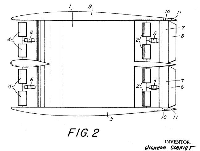
FIG. 3 is a diagrammatic
perspective of another embodiment.

DESCRIPTION OF THE PREFERRED
EMBODIMENTS
Discussing firstly FIGS. 1 and 2, it will be seen that the hull 1 here is of airfoil-shaped profile. It has an unusually dimensioned cabin whose length is greater than its width, contrary to the arrangement which is customary in such craft. At the trailing end of the hull 1 I provide a rotary undulator unit 2 and a stationary deundulator unit 3. These are of the type discussed at length in my aforementioned prior patents and are therefore not in need of detailed explanation.
According to the invention I provide an additional undulator unit 4 at the leading end of the hull 1. As FIG. 2 shows, the unit 2 comprises four vanes arranged along an axis of rotation which extends transversely to the longitudinal axis of the hull, and the unit 4 according to the present invention is similarly subdivided. Of course, fewer or more vanes could be chosen, if desired in accordance with specific requirements. Drive means 5 are provided for the vanes of unit 2, and drive means 6 for those of unit 4. In each case, a planetary-gear drive is also provided for purposes of driving, adjusting and controlling the various vanes. Such drive means and drives are not specifically shown in detail because they are known, e.g. from my aforementioned patents to which reference may be had.
The deundulator consists of two superposed vanes each of which is subdivided as in the case of the units 2 and 4. The vanes of unit 3 are adjustable with reference to one another but do not rotate. The stabilizer 7 with the elevator 8 is located above the unit 3, as far as possible outside any turbulent fluid flow. Reference numeral 9 identifies the sidewalls of the craft, and their trailing ends are configurated (see especially FIG. 2) as lateral stabilizers 10 and carry the rudders 11.
Rotation of the vanes of units 2 and 4 by their respective drives 5 and 6 causes the vanes to convert a portion of the imparted energy into thrust. The residual energy attempts to flow off rearwardly in form of wave energy, that is in form of an undulatory fluid stream. However, this stream impinges either upon the hull 1 or the device 3, both of which serve to deundulate the fluid stream and thus to convert the escaping energy into thrust. This substantially improves the thrust capacity of the units 2 and 4, and the suction effect exerted by the unit 2 in addition serves to reduce the resistance offered by the hull 1 to forward motion, especially if the hull is relatively thick.
It has already been pointed out that the vanes of the units 2 and 4, as well as those of the unit 3, can be adjusted in their relative positions. If the vanes of the unit 2, and those of the unit 3, are adjusted to strongly positive position, that is with their trailing edge facing downwardly, then the fluid stream about the hull 1 is deflected strongly in downward direction with a concomitant strong increase in the lift.
A further increase in lift can be achieved by also and simultaneously adjusting the vanes of unit 4 in negative sense to an extent greater than that used during normal flight. The lift attainable with these measures is so substantial even for a hull having a greater depth than width, that such a hull is enabled to fly. This is analogous with the effect obtained by a jet stream deflector, but the use of the undulator units 2 and 4 affords -- by contrast with such a deflector -- a greater efficiency and a substantial reduction of the total resistance.
Furthermore, the rotating units 2 and 4 serve as stabilizers which prevent undesired tilting or rolling of the hull about its longitudinal axis. The stabilizers 7 and 10 serve, as in conventional airplanes, for stabilizing the hull against movement about its transverse and vertical axes, respectively. The rudders 11 and 8 provide directional control and, if operated in identical sense, serve for vertical control purposes, while they serve for lateral control if operated in opposite senses.
Naturally, and as already pointed out, the invention is not limited to flying craft or to hulls having an airfoil-shaped profile. It is also applicable to hulls of airships and underwater craft which float in their respective medium and require no dynamic lift. Such hulls are usually of more or less teardrop-shaped configuration. This would not be entirely advantageous in conjunction with the already described configuration of the vanes of the unit 4, and it is therefore advantageous to modify the leading end of the hull in such a case (at least over the width of the unit 4) to cooperate better with the unit 4.
Such a construction is shown in FIG. 3 by way of example. The hull is here identified with reference numeral 1a and has teardrop-shaped lateral walls 12 which may be provided with windows 13.
The units 2 and 4 correspond to those in FIGS. 1 and 2. The deundulator unit 3a is provided for the same purpose as the unit 3; however, it is provided with elevators 8a for vertical control. Reference numeral 14 identifies supports for the unit 4, and the front portions of the supports 14 are provided with vertical rudders 15 which are turnable about respective upright axes 15a.
In this as in the preceding embodiments, the intimate connection of the propulsion arrangements with the hull results in a substantial decrease of resistance offered by the craft to movement through its respective fluid medium. Here, also, the unit 2 serves the additional purpose of producing suction on the boundary layer of fluid flowing along the hull; it prevents separation of the boundary layer in the region of the trailing end and thus permits the use of exceptionally thick, and hence shorter, hull shapes.
During movement of the craft shown in FIG. 3, the rudders 11 and 8a control the direction of displacement. The latter rudders serve as light rudders and transverse rudders, depending upon whether they are moved in identical or in opposite directions. This is of course already known.
However, the craft can be directionally controlled even if it floats without a forward component of movement. The vanes of units 2 and 4 rotate in clockwise direction; if they are for instance adjusted in slightly negative sense, meaning with their rear or trailing edge upwardly inclined, then they will provide forward propulsion. If, on the other hand, the hull is to be lifted or lowered, then the vanes of the units 2 and 4 must be adjusted slightly positive or strongly negative, respectively.
By adjusting the vanes of unit 4 to provide rearward propulsion, and those of unit 2 to provide forward propulsion, with adjustment of the rudders 15, 11 in identical directions, the fluid stream producted by the units 2 and 4 is deflected laterally in the same direction and its component of thrust compensated in direction lengthwise of the hull; this results in displacement of the hull in parallelism with itself to one side or the other, depending upon the adjustment of the rudders 15, 11.
On the other hand, if the units 2 and 4 are operated as just described but the rudders 15 are moved in a direction opposite that of the rudders 11, the hull 11 will rotate in place and about an upright axis. This movement, incidentally, is achievable also without using the rudders if the units 2 and 4 each have a set of vanes located at one side of the hull and a separate set located at the other side of the hull, with each set being independently controllable as to its rotation. In that case, the sets of vanes of the units 2 and 4 at one side of the hull are rotated to produce forward thrust, and the sets of vanes at the other side are rotated to produce reverse thrust, with resultant turning of the hull in place.
Naturally, the craft of FIG. 3 could also be utilized as a lighter-than-air flying craft. In that case, the main hull would accommodate gas-filled cells while cabins for passengers and/or holds for cargo would be provided in the sidewalls 12, with still other possibilities suggesting themselves readily to those skilled in the art.
It will be understood that each of the elements described above, or two or more together, may also find a useful application in other types of constructions differing from the types described above.
While the invention has been illustrated and described as embodied in a propulsion arrangement for craft which move in a fluid medium, it is not intended to be limited to the details shown, since various modifications and structural changes may be made without departing in any way from the spirit of the present invention.
Without further analysis, the foregoing will so fully reveal the gist of the present invention that others can by applying current knowledge readily adapt it for various applications without omitting features that, from the standpoint of prior art, fairly constitute essential characteristics of the generic or specific aspects of this invention and, therefore, such adaptations should and are intended to be comprehended within the meaning and range of equivalence of the following claims.
The present invention relates generally to propulsion arrangements, and more especially to propulsion arrangements for craft which move in a fluid medium.
In my prior U. S. Pat. Nos. 3,111,928 and 3,215,371 I have disclosed driving or propulsion arrangements of the general type here in question, for land-, water-and air-craft. The basic concept involved is to provide a hull in the region of its trailing end with a device for undulating a fluid stream which flows from the leading end towards the trailing end and which may be produced in various ways. The undulated stream is then caused to become deundulated by impinging alternately against the opposed sides of a profiled deundulator which is arranged downstream of the undulator. For more specific details, reference may be had to the above-mentioned U. S. Patents.
In these prior constructions the undulator and the deundulator are invariably arranged at the trailing end of the hull. I have now found that it is not only desirable but possible to substantially improve the efficiency of these arrangements, and in addition to impart to craft which are so constructed a greatly enhanced degree of stability and of maneuverability.
SUMMARY OF THE INVENTION
It is, accordingly, an object of the invention to provide the above outlined improvements.
A more particular object is to provide a propulsion arrangement of the type under discussion which has a substantially improved degree of propulsion efficiency.
Another object is to provide such an arrangement which allows better maneuverability of a craft so provided.
Still a further object is to provide an arrangement of this type whose use substantially enhances the stability of a craft which utilizes the arrangement.
In pursuance of the above objects, and others which will become apparent hereafter, the invention resides, briefly stated, in a propulsion arrangement of the type under discussion which combines a hull configurated as a lifting body and propulsion means including drive means and undulator means. The latter is driven by the former and produces an undulatory rearwardly flowing fluid stream which is deundulated by contact with surfaces of the hull. According to the invention the undulator means is located ahead of or at the leading portion of the hull so that the latter can, as just pointed out, serve to effect deundulation of the fluid stream.
The hull is a "lifting body," which is to say that it provides "lift" or buoyancy in a fluid medium. It may be airfoil shaped, teardrop shaped, or it may have positive buoyancy as by being provided with gas-filled compartments or the like. In any case, the hull itself constitutes a deundulator for the fluid stream and this increases the thrust of the same. The thrust will be the larger, the more the leading end portion of the hull is conformed to the elongate shape of the vanes utilized in the undulator device.
The arrangement according to the present invention is intended for use in conjunction with the undulator/deundulator drive provided at the trailing end of the hull, as known from my aforementioned prior U. S. Patents. When used in this manner, my novel arrangement substantially improves the thrust, reduces resistance to movement, increases the stability of the hull about its longitudinal axis, and improves the maneuverability of the craft.
The novel features which are considered as characteristic for the invention are set forth in particular in the appended claims. The invention itself, however, both as to its construction and its method of operation, together with additional objects and advantages thereof, will be best understood from the following description of specific embodiments when read in connection with the accompanying drawings.
BRIEF DESCRIPTION OF THE DRAWING
FIG. 1 is a diagrammatic side view of a craft provided with a propulsion arrangement according to the invention;
FIG. 2 is a top plan view of FIG. 1; and
Discussing firstly FIGS. 1 and 2, it will be seen that the hull 1 here is of airfoil-shaped profile. It has an unusually dimensioned cabin whose length is greater than its width, contrary to the arrangement which is customary in such craft. At the trailing end of the hull 1 I provide a rotary undulator unit 2 and a stationary deundulator unit 3. These are of the type discussed at length in my aforementioned prior patents and are therefore not in need of detailed explanation.
According to the invention I provide an additional undulator unit 4 at the leading end of the hull 1. As FIG. 2 shows, the unit 2 comprises four vanes arranged along an axis of rotation which extends transversely to the longitudinal axis of the hull, and the unit 4 according to the present invention is similarly subdivided. Of course, fewer or more vanes could be chosen, if desired in accordance with specific requirements. Drive means 5 are provided for the vanes of unit 2, and drive means 6 for those of unit 4. In each case, a planetary-gear drive is also provided for purposes of driving, adjusting and controlling the various vanes. Such drive means and drives are not specifically shown in detail because they are known, e.g. from my aforementioned patents to which reference may be had.
The deundulator consists of two superposed vanes each of which is subdivided as in the case of the units 2 and 4. The vanes of unit 3 are adjustable with reference to one another but do not rotate. The stabilizer 7 with the elevator 8 is located above the unit 3, as far as possible outside any turbulent fluid flow. Reference numeral 9 identifies the sidewalls of the craft, and their trailing ends are configurated (see especially FIG. 2) as lateral stabilizers 10 and carry the rudders 11.
Rotation of the vanes of units 2 and 4 by their respective drives 5 and 6 causes the vanes to convert a portion of the imparted energy into thrust. The residual energy attempts to flow off rearwardly in form of wave energy, that is in form of an undulatory fluid stream. However, this stream impinges either upon the hull 1 or the device 3, both of which serve to deundulate the fluid stream and thus to convert the escaping energy into thrust. This substantially improves the thrust capacity of the units 2 and 4, and the suction effect exerted by the unit 2 in addition serves to reduce the resistance offered by the hull 1 to forward motion, especially if the hull is relatively thick.
It has already been pointed out that the vanes of the units 2 and 4, as well as those of the unit 3, can be adjusted in their relative positions. If the vanes of the unit 2, and those of the unit 3, are adjusted to strongly positive position, that is with their trailing edge facing downwardly, then the fluid stream about the hull 1 is deflected strongly in downward direction with a concomitant strong increase in the lift.
A further increase in lift can be achieved by also and simultaneously adjusting the vanes of unit 4 in negative sense to an extent greater than that used during normal flight. The lift attainable with these measures is so substantial even for a hull having a greater depth than width, that such a hull is enabled to fly. This is analogous with the effect obtained by a jet stream deflector, but the use of the undulator units 2 and 4 affords -- by contrast with such a deflector -- a greater efficiency and a substantial reduction of the total resistance.
Furthermore, the rotating units 2 and 4 serve as stabilizers which prevent undesired tilting or rolling of the hull about its longitudinal axis. The stabilizers 7 and 10 serve, as in conventional airplanes, for stabilizing the hull against movement about its transverse and vertical axes, respectively. The rudders 11 and 8 provide directional control and, if operated in identical sense, serve for vertical control purposes, while they serve for lateral control if operated in opposite senses.
Naturally, and as already pointed out, the invention is not limited to flying craft or to hulls having an airfoil-shaped profile. It is also applicable to hulls of airships and underwater craft which float in their respective medium and require no dynamic lift. Such hulls are usually of more or less teardrop-shaped configuration. This would not be entirely advantageous in conjunction with the already described configuration of the vanes of the unit 4, and it is therefore advantageous to modify the leading end of the hull in such a case (at least over the width of the unit 4) to cooperate better with the unit 4.
Such a construction is shown in FIG. 3 by way of example. The hull is here identified with reference numeral 1a and has teardrop-shaped lateral walls 12 which may be provided with windows 13.
The units 2 and 4 correspond to those in FIGS. 1 and 2. The deundulator unit 3a is provided for the same purpose as the unit 3; however, it is provided with elevators 8a for vertical control. Reference numeral 14 identifies supports for the unit 4, and the front portions of the supports 14 are provided with vertical rudders 15 which are turnable about respective upright axes 15a.
In this as in the preceding embodiments, the intimate connection of the propulsion arrangements with the hull results in a substantial decrease of resistance offered by the craft to movement through its respective fluid medium. Here, also, the unit 2 serves the additional purpose of producing suction on the boundary layer of fluid flowing along the hull; it prevents separation of the boundary layer in the region of the trailing end and thus permits the use of exceptionally thick, and hence shorter, hull shapes.
During movement of the craft shown in FIG. 3, the rudders 11 and 8a control the direction of displacement. The latter rudders serve as light rudders and transverse rudders, depending upon whether they are moved in identical or in opposite directions. This is of course already known.
However, the craft can be directionally controlled even if it floats without a forward component of movement. The vanes of units 2 and 4 rotate in clockwise direction; if they are for instance adjusted in slightly negative sense, meaning with their rear or trailing edge upwardly inclined, then they will provide forward propulsion. If, on the other hand, the hull is to be lifted or lowered, then the vanes of the units 2 and 4 must be adjusted slightly positive or strongly negative, respectively.
By adjusting the vanes of unit 4 to provide rearward propulsion, and those of unit 2 to provide forward propulsion, with adjustment of the rudders 15, 11 in identical directions, the fluid stream producted by the units 2 and 4 is deflected laterally in the same direction and its component of thrust compensated in direction lengthwise of the hull; this results in displacement of the hull in parallelism with itself to one side or the other, depending upon the adjustment of the rudders 15, 11.
On the other hand, if the units 2 and 4 are operated as just described but the rudders 15 are moved in a direction opposite that of the rudders 11, the hull 11 will rotate in place and about an upright axis. This movement, incidentally, is achievable also without using the rudders if the units 2 and 4 each have a set of vanes located at one side of the hull and a separate set located at the other side of the hull, with each set being independently controllable as to its rotation. In that case, the sets of vanes of the units 2 and 4 at one side of the hull are rotated to produce forward thrust, and the sets of vanes at the other side are rotated to produce reverse thrust, with resultant turning of the hull in place.
Naturally, the craft of FIG. 3 could also be utilized as a lighter-than-air flying craft. In that case, the main hull would accommodate gas-filled cells while cabins for passengers and/or holds for cargo would be provided in the sidewalls 12, with still other possibilities suggesting themselves readily to those skilled in the art.
It will be understood that each of the elements described above, or two or more together, may also find a useful application in other types of constructions differing from the types described above.
While the invention has been illustrated and described as embodied in a propulsion arrangement for craft which move in a fluid medium, it is not intended to be limited to the details shown, since various modifications and structural changes may be made without departing in any way from the spirit of the present invention.
Without further analysis, the foregoing will so fully reveal the gist of the present invention that others can by applying current knowledge readily adapt it for various applications without omitting features that, from the standpoint of prior art, fairly constitute essential characteristics of the generic or specific aspects of this invention and, therefore, such adaptations should and are intended to be comprehended within the meaning and range of equivalence of the following claims.
US3111928
Driving Arrangement for and / Air / Water Craft
Driving Arrangement for and / Air / Water Craft
US3215371
Driving Arrangement...


Driving Arrangement...
GB 944244
Improvements...
Improvements...


DE 3120345
Propeller drive
Propeller drive


Abstract -- A propeller drive, in particular for aircraft and watercraft, has at least two propeller blades (2), which are arranged on a drive shaft (3), are aligned with respect to the axial direction, and have an intake side (4) and a thrust side (5). In order to provide a propeller drive suitable likewise for watercraft and aircraft, including inter alia VTOL aircraft such as, for example, helicopters, the thrust that can be used for propulsion being substantially increased in conjunction with an equal or smaller diameter (D) than conventional propellers, the noise development of which propeller drive is lower, at least in subsonic operation, than known propellers, and which propeller drive is suitable for gaseous working agents for use in supersonic operation and which, furthermore, effectively utilises for propulsion the underpressure produced and unused on the intake side (4); in conventional propellers, radial blades (2) having an axial extent (L) and bounded at the end face by a disc (6) adjoin the propeller blades (1) on the thrust side (5), flow surfaces (12) being arranged over a portion of the axial extent (L) between the radial blades (2) from the drive shaft (3) approximately up to the circumferential rim (11) of a disc (6), and it holds for the ratio of the axial extent (L) of the radial blades (2) to the diameter (D) of the propeller blades (1) on their intake side (4) that L/D >/= 0.25.