Spiro
Ross SPIROS
Electrolysis
Electrolysis
Improvements
by the co-inventor of Yull Brown's HHO gas generator :
claims 3 forms of over-unity
http://www.bibliotecapleyades.net/ciencia/ciencia_quantum08.htm
Ross
Spiros
Australian inventor and past business partner and researcher with Yul Brown (the famous Australian that put the hydrogen revolution on the map with his “Brown Gas’ technologies).
Mr. Spiros went on to refine and improve the efficiencies and commercialization of the original inventions by producing a unique technology where the cells are cost effective, efficient and can produce all transportation fuels commercially.
Ross is co-owner of Eco Global Fuels LLC, the world’s first and only producer of 100 percent renewable, alcohol-based transportation fuels, using water, sunlight and catalysis’s. Decades of research have enabled the technology to harness the power of water and sunlight for the manufacture of hydrogen in the most efficient, cost-effective and ecologically sound manner ever created.
When combined with carbon dioxide extracted from the atmosphere, this hydrogen is immediately converted into an alcohol-based liquid fuel for safe and reliable transport.
PATENTS
IMPROVEMENTS
IN ELECTROLYSIS SYSTEMS AND THE AVAILABILITY OF OVER-UNITY
ENERGY
WO9528510
AU2248695
WO9528510
AU2248695
A looped energy system for the generation of excess energy available to do work is disclosed. The system comprises an electrolysis cell unit (150) receiving a supply of water to liberate separated hydrogen gas (154) and oxygen (156) by electrolysis driven by a DC voltage (152) applied across respective anodes and cathodes of the cell unit (150). A hydrogen gas receiver (158) receives and stores hydrogen gas liberated by the cell unit (150), and an oxygen gas receiver (160) receives and stores oxygen gas liberated by the cell unit (150). A gas expansion device (162) expands the stored gases to recover expansion work, and a gas combustion device (168) mixes and combusts the expanded hydrogen gas and oxygen gas to recover combusted work. A proportion of the sum of the expansion work and the combustion work sustains electrolysis of the cell unit to retain operational gas pressure in the gas receivers (158, 160) such that the energy system is self-sustaining, and there is excess energy available from the sum of energies.
Technical Field of the Invention
The present invention relates to the generation of hydrogen gas and oxygen gas from water, either as an admixture or as separated gases, by the process of electrolysis, and relates further to applications for the use of the liberated gas. Embodiments of the invention relate particularly to apparatus for the efficient generation of these gases, and to use of the gases in an internal combustion engine and an implosion pump. The invention also discloses a closed-loop energy generation system where latent molecular energy is liberated as a form of 'free energy' so the system can be self-sustaining.
Reference is made to commonly-owned International patent application No.PCT/AU94/000532, having the International filing date of 6 September 1994.
Background Art
The technique of electrolysing water in the presence of an electrolyte such as sodium hydroxide (NaOH) or potassium hydroxide (KOH) to liberate hydrogen and oxygen gas (H2, 02) is well known. The process involves applying a DC potential difference between two or more anode/cathode electrode pairs and delivering the minimum energy required to break the H-O bonds (i.e. 68.3 kcal per mole @ STP).
The gases are produced in the stoichiometric proportions for O2:H2 of 1:2 liberated respectively from the anode (+) and cathode (-).
Reference can be made to the following texts: "Modern Electrochemistry, Volume 2, John O'M. Bockris and Amulya K.N. Reddy, Plenum Publishing Corporation", "Electro-Chemical Science, J. O'M. Bockris and D.M. Drazic, Taylor and Francis Limited" and "Fuel Cells, Their Electrochemistry, J. O'M. Bockris and S. Srinivasan, McGraw-Hill Book Company".
A discussion of experimental work in relation to electrolysis processes can be obtained from "Hydrogen Energy, Part A, Hydrogen Economy Miami Energy Conference, Miami Beach, Florida, 1974, edited by T. Nejat Veziroglu, Plenum Press". The papers presented by J. O'M. Bockris on pages 371 to 379, by F.C. Jensen and F.H. Schubert on pages 425 to 439 and by John B. Pangborn and John C. Sharer on pages 499 to 508 are of particular relevance.
On a macro-scale, the amount of gas produced depends upon a number of variables, including the type and concentration of the electrolytic solution used, the anode/cathode electrode pair surface area, the electrolytic resistance (equating to ionic conductivity, which is a function of temperature and pressure), achievable current density and anode/cathode potential difference. The total energy delivered must be sufficient to disassociate the water ions to generate hydrogen and oxygen gases, yet avoid plating (oxidation/reduction) of the metallic or conductive non-metallic materials from which the electrodes are constructed.
Disclosure of the Invention
The invention discloses a looped energy system for the generation of excess energy available to do work, said system comprising: an electrolysis cell unit receiving a supply of water and for liberating separated hydrogen gas and oxygen gas by electrolysis due to a DC voltage applied across respective anodes and cathodes of said cell unit; hydrogen gas receiver means for receiving and storing hydrogen gas liberated by said cell unit; oxygen gas receiver means for receiving and storing oxygen gas liberated by said cell unit; gas expansion means for expanding said stored gases to recover expansion work; and gas combustion means for mixing and combusting said expanded hydrogen gas and oxygen gas to recover combustion work; and wherein a proportion of the sum of the expansion work and the combustion work sustains electrolysis of said cell unit to retain operational gas pressure in said hydrogen and oxygen gas receiver means such that the energy system is self-sustaining and there is excess energy available from said sum of energies.
The invention further discloses a looped energy system for the generation of excess energy available to do work, said system comprising: an electrolysis cell unit receiving a supply of water and for liberating separated hydrogen gas and oxygen gas by electrolysis due to a DC voltage applied across respective anodes and cathodes of said cell unit; hydrogen gas receiver means for receiving and storing hydrogen gas liberated by said cell unit; oxygen gas receiver means for receiving and storing oxygen gas liberated by said cell unit; gas expansion means for expanding said stored gases to recover expansion work; and fuel cell means for recovering electrical work from said expanded hydrogen gas and oxygen gas; and wherein a proportion of the sum of the expansion work and the recovered electrical work sustains electrolysis of said cell unit to retain operational gas pressure in said hydrogen and oxygen gas receiver means such that the energy system is self-sustaining and there is excess energy available from said sum of energies.
The invention further discloses a method for the generation of excess energy available to do work by the process of electrolysis, said method comprising the steps of: electrolysing water by a DC voltage to liberate separated hydrogen gas and oxygen gas; separately receiving and storing said hydrogen gas and oxygen gas in a manner to be self-pressuring; separately expanding said stores of gas to recover expansion work; combusting said expanded gases together to recover combustion work; and applying a portion of the sum of the expansion work and the combustion work as said DC voltage to retain operational gas pressures and sustain said electrolysing step, there thus being excess energy of said sum available.
The invention further discloses a method for the generation of excess energy available to do work by the process of electrolysis, said method comprising the steps of: electrolysing water by a DC voltage to liberate separated hydrogen gas and oxygen gas; separately receiving and storing said hydrogen gas and oxygen gas in aniaaner to be self-pressuring; separately expanding said stores of gas to recover expansion work; passing said expanded gases together through a fuel cell to recover electrical work; and applying a portion of the sum of the expansion work and the recovered electrical work as said DC voltage to retain operational gas pressures and sustain said electrolysing step, there thus being excess energy of said sum available.
The invention further discloses an internal combustion engine powered by hydrogen and oxygen comprising: at least one cylinder and at least one reciprocating piston within the cylinder; a hydrogen gas input port in communication with the cylinder for receiving a supply of pressurised hydrogen; an oxygen gas input port in communication with the cylinder for receiving a supply of pressurised oxygen; and an exhaust port in communication with the cylinder and wherein the engine is operable in a two-stroke manner whereby, at the top of the stroke, hydrogen gas is supplied by the respective inlet port to the cylinder driving the piston downwardly, oxygen gas then is supplied by the respective inlet port to the cylinder to drive the cylinder further downwardly, after which time self-detonation occurs and the piston moves to the bottom of the stroke and upwardly again with said exhaust port opened to exhaust water vapour resulting from the detonation.
The invention further discloses an implosion pump comprising a combustion chamber interposed, and in communication with, an upper reservoir and a lower reservoir separated by a vertical distance across which water is to be pumped, said chamber receiving admixed hydrogen and oxygen at a pressure sufficient to lift a volume of water the distance therefrom to the top reservoir, said gas in the chamber then being combusted to create a vacuum in said chamber to draw water from said lower reservoir to fill said chamber, whereupon a pumping cycle is established and can be repeated.
The invention further discloses a parallel stacked arrangement of cell plates for a water electrolysis unit, the cell plates alternately forming an anode and cathode of said electrolysis unit, and said arrangement including separate hydrogen gas and oxygen gas outlet port means respectively in communication with said anode cell plates and said cathode cell plates and extending longitudinally of said stacked plates, said stacked cell plates being configured in the region of said conduits to mate in a complementary manner to form said conduits such that a respective anode cell plate or cathode cell plate is insulated from the hydrogen gas conduit or the oxygen gas conduit.
Brief Description of the Drawings
Figs. 1 1a-16 of noted International application no. PCT/AU94/000532 are reproduced to aid description of the present invention, but herein denoted as Figs. la-6:
Figs. la and 1b show an embodiment of a cell plate;
Figs. 2a and 2b show a complementary cell plate to that of Figs. la and lb;
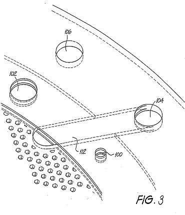
Fig. 3 shows detail of the perforations and porting of the cell plates of Figs. la, lb, 2a and 2b;
Fig. 4 shows an exploded stacked arrangement of the cell plates of Figs. la, lb, 2a and 2b;
Fig. 5a shows a schematic view of the gas separation system of Fig. 4;
Fig. 5b shows a stylised representation of Fig. 5a;
Fig. 5c shows an electrical equivalent circuit of Fig. 5a; and
Fig. 6 shows a gas collection system for use with the cell bank separation system of Figs. 4 and 5a.
The remaining drawings are:
Figs. 7a and 7b are views of a first cell plate;
Figs. 8a and 8b are views of a second cell plate;
Fig. 9 shows detail of the edge margin of the first cell plate;
Fig. 10 shows an exploded stacked arrangement of the cell plates shown in Figs. 7a and 8a;
Fig. 11 is a cross-sectional view of three of the stacked cell plates shown in
Fig. 10 in the vicinity of a gas port;
Figs. 12a and 12b respectively show detail of the first and second cell plates in the vicinity of a gas port;
Fig. 13 is a cross-sectional view of a cell unit of four stacked cell plates in the vicinity of an interconnecting shaft;
Fig. 14 shows a perspective view of a locking nut used in the arrangement of Fig. 13;
Fig. 15 shows an idealised electrolysis system;
Figs. 16-30 are graphs supporting the system of Fig. 15 and the availability of over-unity energy;
Figs. 31a to 31e show a hydrogen/oxygen gas-driven internal combustion engine; and
Figs. 32a-32c show a gas-driven implosion pump.


Detalled Description and Best Mode of Performance
The following description of Figs. la-6 is taken from PCT/AU94/000532.
Figs. la and 2a show embodiments of a first and second type of cell plate 90,98 as an end view. Figs. 1b and 2b are partial cross-sectional views along the respective mid-lines as shown. Common reference numerals have been used where appropriate. The plates 90,98 can have the function of either an anode (+) or a cathode (-), as will become apparent. Each comprises an electrode disc 92 that is perforated with hexagonally shaped holes 96. The disc 92 is made from steel or resinbonded carbon or conductive polymer material. The disc 92 is housed in a circular rim or sleeve 94. The function of the perforations 96 is to maximise the surface area of the electrode disc 92 and minimise the weight over solid constructions by 45 %.
By way of example, for a disc of diameter 280 mm, the thickness of the disc must be 1 mm in order to allow the current density (which ranges from 90 A / 2,650 cm2 - 100 A / 2,940 cm2 of the anode or cathode) to be optimal. If the diameter of the plate is increased, which consequently increases the surface area, it is necessary to increase the thickness of the plate in order to maintain uniformity of conductance for the desired current density.
The hexagonal perforations in a 1 mm disc have a distance of 2 mm between the flats, twice the thickness of the plate in order to maintain the same total surface area prior to perforation, and be 1 mm away from the next adjacent perforation to allow the current density to be optimal. A 1 mm (flat-to-flat) distance between the hexagonal perforations is required, because a smaller distance will result in thermal losses and a larger distance will add to the overall weight of the plate.
The sleeve 94 is constructed of PVC material and incorporates a number of equally spaced shaft holes 100,102. The holes are for the passage of interconnecting shafts provided in a stacked arrangement of the plates 90,98 forming the common conductor for the respective anode and cathode plates. The further two upper holes 104,106 each support a conduit respectively for the out-flow of oxygen and hydrogen gases. The further holes 108,110 at the bottom of the sleeve 94 are provided for the inlet of water and electrolyte to the respective cell plates 90,98.
Fig. 3 shows an enlarged view of a portion of the cell plate 90 shown in Fig.la. The port hole 104 is connected to the hexagonal perforations 96 within the sleeve 94 by an internal channel 112. A similar arrangement is in place for the other port hole 106, and for the water/electrolyte supply holes 108,110.
If it is the case that the hydrogen and oxygen gases liberated are to be kept separate (i.e. not to be formed as an admixture), then it is necessary to separate those gases as they are produced. In the prior art this is achieved by use of diaphragms that block the passage of gases and effectively isolate the water/electrolyte on each side of the diaphragm. Ionic transfer thus is facilitated by the ionically conductive nature of the diaphragm material (i.e. a water - diaphragm - water path). This results in an increase in the ionic resistance and hence a reduction in efficiency.
Fig. 4 shows an exploded stacked arrangement of four cell plates, being an alternative stacking of two (anode) cell plates 90 and two (cathode) cell plates 98. The two ends of the stacked arrangement of cell plates delineates a single cell unit 125.
Interposed between each adjacent cell plate 90,98 is a PTFE separation 116. Although not shown in Fig. 4, the cell unit includes separate hydrogen and oxygen gas conduits that respectively pass through the stacked arrangement of cell plates via the port holes 106,104 respectively. In a similar way, conduits are provided for the supply of water/electrolyte, respectively passing through the holes 108,110 at the bottom of the respective plates 90,98. Only two pairs of anode/cathode cell plates are shown. The number of such plates can be greatly increased per cell unit 125.
Also not shown are the interconnecting conductive shafts that electrically interconnect alternative common cell plates. The reason for having a large diameter hole in one cell plate adjacent to a smaller diameter hole in the next cell plate, is so that an interconnecting shaft will pass through the larger diameter hole, and not make an electrical connection (i.e. insulated with PVC tubing) rather only forming an electrical connection between alternate (common) cell plates.
The cell unit 125 shown in Fig. 4 arrangement is an exploded view. When fully constructed, all the elements are stacked to be in intimate contact. Mechanical fastening is achieved by use of one of two adhesives such as (a) "PUR-FECT LOK" (TM) 34-9002, which is a Urethane Reactive Hot Melt adhesive with a main'ingredient of Methylene Bispheny/Dirsocynate (MDI), and (b) "MY-T-BOND" (TM) which is a PVC solvent based adhesive. Both adhesives are Sodium Hyroxide (20% present in the electrolyte) resistant. In that case the water/electrolyte only resides within the area proscribed by the cell plate sleeve 94. Thus the only path for the inlet of water/electrolyte is by bottom channels 118,122 and the only outlet for the gases is by the top channels 112,120.In a system constructed and tested by the inventor, the thickness of the cell plates 90,98 is 1 mm (2 mm on the rim because of the PVC sleeve 94), with a diameter of 336 mm. The cell unit 125 is segmented from the next cell by an insulating PVC segmentation disc 114. A segmentation disc 114 also is placed at the beginning and end of the entire cell bank.
If there is to be no control over separation of the liberated gases, then the PTFE membranes 116 are not provided, nor is the sleeve 94 required.The PTFE membrane 116 is fibrous and has 0.2 to 1.0 micron interstices. A suitable type is type Catalogue Code J, supplied by Tokyo Roshi International Inc (Advantec).
The water/electrolyte fills the interstices and ionic current flows only via the water - there is no contribution of ionic flow through the PTFE material itself. This leads to a reduction in the resistance to ionic flow. The PTFE material also has a 'bubble point' that is a function of pressure, hence by controlling the relative pressures at either side of the PTFE separation sheets, the gases can be 'forced' through the interstices to form an admixture, or otherwise kept separate. Other advantages of this arrangement include a lesser cost of construction, improved operational efficiency and greater resistance to faults.
Fig. 5a is a stylised, and exploded, schematic view of a linear array of three series-connected cell units 125. For clarity, only six interconnecting shafts 126-131 are shown. The shafts 126-131 pass through the respective shaft holes 102,100 in the various cell plates 90,98 in the stacked arrangement. The polarity attached to each of the exposed end shafts, to which the DC supply is connected also is indicated. The shafts 126-131 do not run the full length of the three cell banks 125. The representation is similar to the arrangement shown in Figs. 7a and 8. One third the full DC source voltage appears across each anode/cathode cell plate pair 90,98.
Further, the gas conduits 132,133, respectively for hydrogen and oxygen, that pass through the port holes 104,106 in the cell plates 90,98 also are shown. In a similar way, water/electrolyte conduits 134,135, passing through the water port holes 108,110 in the cell plates also are shown.
Fig. 5b particularly shows how the relative potential difference in the middle cell bank 125 changes. That is, the plate electrode 90a now functions as a cathode (i.e.relatively more negative) to generate hydrogen, and the plate electrode 98a now functions as an anode (i.e. relatively more positive) to generate oxygen. This is the case for every alternate cell unit. The arrowheads shown in Fig. 5b indicate the electron and ionic current circuit. Fig. Sc is an electrical equivalent circuit representation of Fig. 5b, where the resistive elements represent the ionic resistance between adjacent anode/cathode plates. Thus it can be seen that the cell units are connected in series.
Because of the change of function of the cell plates 90a and 98a, the complementary gases are liberated at each, hence the respective channels 112 are connected to the opposite gas conduit 132,133. Practically, this can be achieved by the simple reversal of the cell plates 90,98.
Fig. 6 shows the three cell units 125 of Fig. 5a connected to a gas collection arrangement. The cell units 125 are located within a tank 140 that is filled with water/electrolyte to the level h indicated. The water is consumed as the electrolysis process proceeds, and replenishing supply is provided via the inlet 152. The water/electrolyte level h can be viewed via the sight glass 154. In normal operation, the different streams of hydrogen and oxygen are produced and passed from the cell units 125 to respective rising columns 142,144. That is, the pressure of electrolyte on opposed sides of the PTFE membranes 116 is equalised, thus the gases cannot admix.
The columns 142, 144 also are filled with the water/electrolyte, and as it is consumed at the electrode plates, replenishing supply of electrolyte is provided by way of circulation through the water/electrolyte conduits 134,135. The circulation is caused by entrainment by the liberated gases, and by the circulatory inducing nature of the conduits and columns.
The upper extent of the tank 140 forms two scrubbing towers 156,158, respectively for the collection of oxygen and hydrogen gases. The gases pass up a respective column 142,144, and out from the columns via openings therein at a point within the interleaved baffles 146. The point where the gases exit the columns 142,144 is
beneath the water level h, which serves to settle any turbulent flow and entrained electrolyte. The baffles 146 located above the level h scrub the gas of any entrained electrolyte, and the scrubbed gas then exits by respective gas outlet columns 148,150 and so to a gas receiver. The level h within the tank 140 can be regulated by any convenient means, including a float switch, again with the replenishing water being supplied by the inlet pipe 152.
The liberated gases will always separate from the water/electrolyte solution by virtue of the difference in densities. Because of the relative height of the respective set of baffles, and due to the density differential between the gases and the water/electrolyte, it is not possible for the liberated hydrogen and oxygen gases to mix.
The presence of the full volume of water within the tank 140 maintains the cell plates in an immersed state, and further serves to absorb the shock of any internal detonations should they occur.
In the event that a gas admixture is required, then firstly the two flow valves 136,137 respectively located in the oxygen gas outlet conduit 132 and water/electrolyte inlet port 134 are closed. This blocks the outlet path for the oxygen gas and forces the inlet water/electrolyte to pass to the inlet conduit 134 via a one-way check valve 139 and pump 138. The water/electrolyte within the tank 140 is under pressure by virtue of its depth (volume), and the pump 138 operates to increase the pressure of water/electrolyte occurring about the anode cell plates 90,98a to be at an increased pressure with respect to the water/electrolyte on the other side of the membrane 116.
This pressure differential is sufficient to cause the oxygen gas to migrate through the membrane, thus admixed oxygen and hydrogen are liberated via the gas output conduit 133 and column 144. Since there is no return path for the water/electrolyte supplied by the pump 138, the pressure about the cell plates 90,98a will increase further, and to a point where the difference is sufficient such that the water/electrolyte also can pass through the membrane 116. Typically, pressure differential in the range of 1.5 - 10 psi is required to allow passage of gas, and a pressure differential in the range of 10 - 40 psi for water/electrolyte.
While only three cell units 125 are shown, clearly any number, connected in series, can be implemented.
Embodiments of the present invention now will be described. Where applicable, like reference numerals have been used.
Figs. 7a and 7b show a first type of cell plate 190 respectively as an end view and as an enlarged cross-sectional view along line VIIb-VIIb. The cell plate 190 differs from the previous cell plate 90 shown in Figs. la and 1b in a number of important aspects. The region of the electrode disc 192 received within the sleeve 194 now is perforated. The function of these perforations is to further reduce the weight of the cell plate 190. The shaft holes 200,202 again pass through the electrode disc 192, but so too do the upper holes 204,206 through which the conduits for the out-flow of liberated hydrogen and oxygen gases pass. The bottom holes 208,210, provided for the inlet of water and electrolyte, now also are located in the region of the sleeve 194 coincident with the perforated edge margin of the electrode disc 192.The channels 212,218 respectively communicating with the port hole 204 and the supply hole 210 also are shown.
Figs. 8a and 8b show a second type of cell plate 198 as a companion to the first cell plate 190, and as the same respective views. The second cell plate 198 is somewhat similar to the cell plate 98 previously shown in Figs. 2a and 2b. The differences therebetween are the same as the respective differences between the cell plate shown in Figs. la and 1b and the one shown in Figs. 7a and 7b. The arrangement of the respective channels 220,222 with respect to the port 206 and the water supply hole 208 also are shown.
In the fabrication of the cell plates 190,198, the sleeve 94 is injection moulded from PVC plastics material formed about the edge margin of the electrode disc 192.
The injection moulding process results in the advantageous forming of interconnecting sprues forming within the perforations 196 in the region of the disc 192 held within the sleeve 194, thus firmly anchoring the sleeve 194 to the disc 192.
Fig. 9 is a view similar to Fig. 3, but for the modified porting arrangement and perforations (shown in phantom where covered by the sleeve) of the region of the disc 192 within and immediately outside of the sleeve 194.
Fig. 10 shows a cell unit 225 in the form of an exploded alternating stacking of first and second cell plates 190,198, much in the same manner as Fig. 4. Only two pairs of anode/cathode cell plates are shown, however the number of such plates can be greatly increased per cell unit 225. The membrane 216 preferably is type QR-HE silica fibre with the alternative being PTFE. Both are available from Tokyo Roshi International Inc. (Advantec) of Japan. Type QR-HE is a hydrophobic material having 0.2 to 1.0 micron interstices, and is capable of operation at temperatures up to 10000C.
The cell unit 225 can be combined with other such cell units 225 to form an interconnected cell bank in the same manner as shown in Figs. 5a, 5b and 5c.
Furthermore, the cell units can be put to use in a gas collection arrangement such as that shown in Fig. 6. Operation of the gas separation system utilising the new cell plates 190,198 is in the same manner as previously described.
Fig. 11 is an enlarged cross-sectional view of three cell plates in the vicinity of the oxygen port 204. The cell plates comprise two of the first type of plate 190 shown in Fig. 7a constituting a positive plate, and a single one of the second type of plate 198 shown in Fig. 8a representing a negative plate. The location of the respective channels 212 for each of the positive cell plates 190 is shown as a dashed representation. The respective sleeves 194 of the three cell plates are formed from moulded PVC plastics as previously described, and in the region that forms the perimeter of the port 204 have a configuration particular to whether a cell plate is positive or negative. In the present case, the positive cell plates 190 have a flanged foot 230 that, in the assembled construction, form the contiguous boundary of the gas port 204.Each foot 230 has two circumferential ribs 232 that engage corresponding circumferential grooves 234 in the sleeve 194 of the negative plate 198.
The result of this arrangement is that the exposed metal area of the negative cell plates 198 always are insulated from the flow of oxygen gas liberated from the positive cell plates 190, thus avoiding the possibility of spontaneous explosion by the mixing of the separated hydrogen and oxygen gases. This arrangement also obviates the unwanted production of either oxygen gas or hydrogen gas in the gas port.
For the case of the gas port 206 carrying the hydrogen gas, the relative arrangement of the cell plates is reversed such that a flanged footing now is formed on the sleeve 194 of the other type of cell plate 198. This represents the converse arrangement to that shown in Fig. 11.
Figs. 12a and 12b show perspective side views of adjacent cell plates, with Fig. 12a representing a positive cell plate 190 and Fig. 12b representing a negative cell plate 198. The gas port 206 thus formed is to carry hydrogen gas. The mating relationship between the flanged foot 230 and the end margin of the sleeve 194 of the positive cell plate 192 can be seen, particularly the interaction between the ribs 232 and the grooves 234.
Fig. 13 is a cross-sectional view of four cell plates formed into a stacked arrangement delimited by two segmentation plates 240, together forming a cell unit 242.
Thus there are two positive cell plates 190 and two negative cell plates 198 in alternating arrangement. The cross-section is taken in the vicinity of a shaft hole 202 through which a negative conductive shaft 244 passes. The shaft 244 therefore is in intimate contact with the electrode discs 192 of the negative cell plates 198. The electrodes discs 192 of the positive cell plates 190 do not extend to contact the shaft 244. The sleeve 194 of the alternating negative cell plates 198 again have a form of flanged foot 246, although in this case the complementarily shaped ribs and grooves are formed only on the sleeve of the negative cell plates 198, and not on the sleeve 194 of the positive cell plates 190.The segmentation plates 240 serve to delimit the stacked plates forming a single cell unit 242, with ones of the cell units 242 being stacked in a linear array to form a cell bank such as has been shown in Fig. Sa.
A threaded shaft nut 250 acts as a spacer between adjacent electrodes connecting with the shaft 244. Fig. 14 is a perspective view of the shaft nut 250 showing the thread 252 and three recesses 254 for fastening nuts, screws or the like.
In all of Figs. 11 to 13, the separation membrane material 216 is not shown, but is located in the spaces 248 between adjacent cell plates 190,198, extending to the margins of the electrode disks 192 in the vicinity of the gas ports 204,206 or the shaft holes 200,202.
An electrolysis hydrogen and oxygen gas system incorporating a gas separation system, such as has been described above, can therefore be operated to establish respective high pressure stores of gas. That is, the separated hydrogen and oxygen gases liberated by the electrolysis process are stored in separate gas receivers or pressure vessels. The pressure in each will increase with the continuing inflow of gas.
Fig. 15 shows an idealised electrolysis system, comprising an electrolysis cell 150 that receives a supply of water to be consumed. The electrolysis process is driven by a DC potential (Es) 152. The potential difference applied to the cell 150 therefore must be sufficient to electrolyse the water into hydrogen and oxygen gas dependent upon, inter alia, the water pressure PC and the back pressure of gas PB acting on the surface of the water, together with the water temperature Tc. The separate liberated hydrogen and oxygen gases, by a priming function, are pressurised to a high value by storage in respective pressure vessels 158,160, being carried by gas lines 154,156.
The pressurised store of gases then are passed to an energy conversion device that converts the flow of gas under pressure to mechanical energy (e.g. a pressure drop device 162). This mechanical energy recovered WM is available to be utilised to provide useful work. The mechanical energy WM also can be converted into electrical form, again to be available for use.
The resultant exhausted gases are passed via lines 164,166 to a combustion chamber 168. Here the gases are combusted to generate heat QR, with the waste product being water vapour. The recovered heat QR can be recycled to the electrolysis cell to assist in maintaining the advantageous operating temperature of the cell.
The previously described combustion chamber 168 can alternatively be a fuel cell. The type of fuel cell can vary from phosphoric acid fuel cells through to molten carbonate fuel cells and solid oxide cells. A fuel cell generates both heat (QR) and electrical energy (WE), and thus can supply both heat to the cell 150 or to supplement or replace the DC supply (Es) 152.
Typically, these fuel cells can be of the type LaserCellTM as developed by Dr Roger Billings, the PEM Cell as available from Ballard Power Systems Inc. Canada or the Ceramic Fuel Cell (solid oxide) as developed by Ceramic Fuel Cells Ltd. Melbourne, Australia.
It is, of course, necessary to replenish the pressurised store of gases, thus requiring the continuing consumption of electrical energy. The recovered electrical energy WE is in excess of the energy required to drive electrolysis at the elevated temperature and is used to replace the external electrical energy source 152, thereby completing the energy loop after the system is initially primed and started.
The present inventor has determined that there are some combinations of pressure and temperature where the efficiency of the electrolysis process becomes advantageous in terms of the total energy recovered, either as mechanical energy by virtue of a flow of gas at high pressure or as thermal energy by virtue of combustion (or by means of a fuel cell), with respect to the electrical energy consumed, to the extent of the recovered energy exceeding the energy required to sustain electrolysis at the operational pressure and temperature. This has been substantiated by experimentation. This notion has been termed "over-unity".
"Over-unity" systems can be categorised as broadly falling into three types of physical phenomena:
(i) An electrical device which produces 100 Watts of electrical energy as output after 10 Watts of electrical energy is input thereby providing 90 Watts of overunity (electrical) energy.
(ii) An electro-chemical device such as an electrolysis device where 10 Watts of electrical energy is input and 8 Watts is output being the thermal value of the hydrogen and oxygen gas output. During this process, 2 Watts of electrical energy converted to thermal energy is lost due to specific inefficiencies of the electrolysis system. Pressure - as the over-unity energy - is irrefutably produced during the process of hydrogen and oxygen gas generation during electrolysis.
Pressure is a product of the containment of the two separated gases. The Law of Conservation of Energy (as referenced in "Chemistry Experimental Foundations", edited by Parry, R.W.; Steiner, L.E.; Tellefsen, R.L.; Dietz, P.M. Chap. 9, pp. 199-200, Prentice-Hall, New Jersey" and "An Experimental Science", edited by Pimentel, G.C., Chap. 7, pp. 115-117, W.H. & Freeman Co. San Francisco) is in equilibrium where the 10 watts of input equals the 8 watts thermal energy output plus the 2 watts of losses. However, this Law ends at this point. The present invention utilises the apparent additional energy being the pressure which is a by-product of the electrolysis process to achieve over-unity.
(iii) An electro-chemical device which produces an excess of thermal energy after an input of electrical energy in such devices utilised in "cold fusion" e.g.10 watts of electrical energy as input and 50 watts of thermal energy as output.
The present invention represents the discovery of means by which the abovementioned second phenomenon can be embodied to result in "over-unity" and the realisation of 'free' energy. As previously noted, this is the process of liberating latent molecular energy. The following sequence of events describes the basis of the availability of over-unity energy.
In a simple two plate (anode/cathode) electrolysis cell, an applied voltage differential of 1.57 DC Volts draws 0.034 Amps per cm2 and results in the liberation of hydrogen and oxygen gas from the relevant electrode plate. The electrolyte is kept at a constant temperature of 40"C, and is open to atmospheric pressure.
The inefficiency of an electrolytic cell is due to its ionic resistance (approximately 20%), and produces a by-product of thermal energy. The resistance reduces, as does the minimum DC voltage required to drive electrolysis, as the temperature increases. The overall energy required to dissociate the bonding electrons from the water molecule also decreases as the temperature increases. In effect, thermal energy acts as a catalyst to reduce the energy requirements in the production of hydrogen and oxygen gases from the water molecule.
Improvements in efficiency are obtainable by way of a combination of thermal energy itself and the NaOH electrolyte both acting to reduce the resistance of the ionic flow of current.
Thermal 'cracking' of the water molecule is known to occur at 1 5000C, whereby the bonding electrons are dissociated and subsequently 'separate' the water molecule into its constituent elements in gaseous form. This thermal cracking then allows the thermal energy to become a consumable. Insulation can be introduced to conserve thermal energy, however there will always be some thermal energy losses.
Accordingly, thermal energy is both a catalyst and a consumable (in the sense that the thermal energy exites bonding electrons to a higher energetic state) in the electrolysis process. A net result from the foregoing process is that hydrogen is being produced from thermal energy because thermal energy reduces the overall energy requirements of the electrolysis system.
Referring to the graph titled "Flow Rate At A Given Temperature" shown in Fig. 16, it has been calculated that at a temperature of 20000C, 693 litres of hydrogen/oxygen admixed gas (2:1) will be produced. The hydrogen content of this volume is 462 litres. At an energy content of 11 BTUs per litre of hydrogen, this then gives an energy amount of 5082 BTUs (11 x 462). Using the BTU:kilowatt conversion factor of 3413:1, 5082 BTUs of the hydrogen gas equate to 1.49 kW. Compare this with lkW to produce the 693 litres of hydrogen/oxygen (including 463 litres of hydrogen). The usage of this apparatus therefore identifies that thermal energy, through the process of electrolysis, is being converted into hydrogen.These inefficiencies, i.e. increased temperature and NaOH electrolyte, reduce with temperature to a point at approximately 1000"C where the ionic resistance reduces to zero, and the volumetric amount of gases produced per kWh increases.
The lowering of DC voltage necessary to drive electrolysis by way of higher temperatures is demonstrated in the graph in Fig. 17 titled "The Effect of temperature on Cell Voltage".
The data in Figs. 16 and 17 has two sources. Cell voltages obtained from 0 C up to and including 100"C were those obtained by an electrolysis system as described hereinbefore. Cell voltages obtained from 1500C up to 2000"C are theoretical calculations presented by an acknowledged authority in this field, Prof. J. O'M. Bockris. Specifically, these findings were presented in "Hydrogen Energy, Part A, Hydrogen Economy Miami Energy Conference, Miami Beach, Florida, 1974, edited by T. Nejat Veziroglu, Plenum Press" pp. 371-379. These calculations appear on page 374.
By inspection of Fig. 17 and Fig. 18 (titled "Flow Rate of Hydrogen and Oxygen at 2:1"), it can be seen that as temperature increases in the cell, the voltage necessary to dissociate the water molecule is reduced, as is the overall energy requirement. This then results in a higher gas flow per kWh.
As constrained by the limitation of the materials within the system, the operationally acceptable temperature of the system is 1000"C. This temperature level should not, however, be considered as a restriction. This temperature is based on the limitations of the currently commercially available materials. Specifically, this system can utilise material such as compressed Silica Fibre for the sleeve around the electrolysis plate and hydrophobic Silica Fibre (part no. QR-100HE supplied by Tokyo Roshi International Inc., also known as "Advantec") for the diaphragm (as previously discussed) which separates the electrolysis disc plates.In the process of assembling the cells, the diaphragm material and sleeved electrolysis plates 190,198 are adhered to one another by using high-temperature-resistant silica adhesive (e.g. the "Aremco" product "Ceramabond 618" which has an operational tolerance specification of 1000 C).
For the above-described electrolysis cell, for the electrolyte at 10000C and utilising electrical energy at the rate of 1kWh, 167 litres of oxygen and 334 litres of hydrogen per hour will be produced.
The silica fibre diaphragm 116 previously discussed separates the oxygen and hydrogen gas streams by the mechanism of density separation, and produce a separate store of oxygen and hydrogen at pressure. Pressure from the produced gases can range from 0 to 150,000 Atmospheres. At higher pressures, density separation may not occur. In this instance, the gas molecules can be magnetically separated from the electrolyte if required.
In reference to the experiments conducted by Messrs Hamann and Linton (S.D. Hamann and M. Linton, Trans. Faraday Soc. 62,2234-2241. Specifically, page 2240), this research has proven that higher pressures can produce the same effect as higher temperatures in that the conductivity increases as temperature and/or pressure increases. At very high pressures, the water molecule at low temperatures dissociates.
The reason for this is that the bonding electron is more readily removed when under high pressure. The same phenomenon occurs when the bonding electrons are at a high temperature (e.g. 1500"C) but at low pressures.
As shown in Fig. 15, hydrogen and oxygen gases are separated into independent gas streams flowing into separate pressure vessels 158,160 capable of withstanding pressures up to 150,000 Atmospheres. Separation of the two gases thereby eliminates the possibility of detonation. It should also be noted that high pressures can facilitate the use of high temperatures within the electrolyte because the higher pressure elevates the boiling point of water.
Experimentation shows that 1 litre of water can yield 1,850 litres of hydrogen/oxygen (in a ratio of 2: 1) gas mix after discomposition, this significant differential (1:1,850) is the source of the pressure. Stripping the bonding electrons from the water molecule, which subsequently converts liquid into a gaseous state, releases energy which can be utilised as pressure when this occurs in a confined space.
A discussion of experimental work in relation to the effects of pressure in electrolysis processes can be obtained from "Hydrogen Energy, Part A, Hydrogen Economy Miami Energy Conference, Miami Beach, Florida, 1974, edited by T. Nejat Veziroglu, Plenum Press". The papers presented by F.C. Jensen and F.H. Schubert on pages 425 to 439 and by John B. Pangborn and John C. Sharer on pages 499 to 508 are of particular relevance.
Attention must be drawn to the above published material; specifically on page 434, third paragraph, where reference is made to "Fig. 7 shows the effect of pressure on cell voltage...". Fig. 7 on page 436 ("Effect of Pressure on SFWES Single Cell") indicates that if pressure is increased, then so too does the minimum DC voltage.
These quotes were provided for familiarisation purposes only and not as demonstrable and empirical fact. Experimentation by the inventor factually indicates that increased pressure (up to 2,450 psi) in fact lowers the minimum DC voltage.
This now demonstrable fact, whereby increased pressure actually lowers minimum DC voltage, is further exemplified by the findings of Messrs. Nayar, Ragunathan and Mitra in 1979 which can be referenced in their paper: "Development and operation of a high current density high pressure advanced electrolysis cell".
Nayar, M.G.; Ragunathan, P. and Mitra, S.K. International Journal of Hydrogen Energy (Pergamon Press Ltd.), 1980, Vol. 5, pp. 65-74. Their Table 2 on page 72 expressly highlights this as follows: "At a Current density (ASM) of 7,000 and at a temperature of 80"C, the table shows identical Cell voltages at both pressures of 7.6 kg/cm2 and 11.0 kg/cm2. But at Current densities of 5,000, 6,000, 8,000, 9,000 and 10,000 (at a temperature of 80"C), the Cell voltages were lower at a pressure of 11.0 kg/cm2 than at a pressure of 7.6 kg/cm2. "The present invention thus significantly improves on the apparatus employed by Mr. M.G. Nayar et al at least in the areas of cell plate materials, current density and cell configuration.
In the preferred form the electrode discs 192 are perforated mild steel, conductive polymer or perforated resin bonded carbon cell plates. The diameter of the perforated holes 196 is chosen to be twice the thickness of the plate in order to maintain the same total surface area prior to perforation. Nickel was utilised in the noted prior art system. That material has a higher electrical resistance than mild steel or carbon, providing the present invention with a lower voltage capability per cell.
The aforementioned prior art system quotes a minimum current density (after conversion from ASM to Amps per square cm.) at 0.5 Amps per cm2. The present invention operates at the ideal current density, established by experimentation, to minimise cell voltage which is .034 Amps per cm2.
When compared with the aforementioned system, an embodiment of the present invention operates more efficiently due to a current density improvement by a factor of 14.7, the utilisation of better conducting cell plate material which additionally lowers cell voltage, a lower cellivoltage of 1.49 at 800C as opposed to 1.8 volts at 800 C, and a compact and efficient cell configuration.
In order to further investigate the findings of Messrs. M.G. Nayer et al, the inventor conducted experiments utilising much higher pressures. For Nayer et al the pressures were 7.6 kg/cm2 to 11.0 kg/cm2, whereas inventor's pressures were 0 psi to 2450 psi in an hydrogen/oxygen admixture electrolysis system.
This electrolysis system was run from the secondary coil of a transformer set approximately at maximum 50 Amps and with an opencircuit voltage of 60 Volts. In addition, this electrolysis system is designed with reduced surface area in order that it can be housed in an hydraulic container for testing purposes. The reduced surface area subsequently caused the gas production efficiency to drop when compared with previous (i.e. more efficient) prototypes. The gas flow rate was observed to be approximately 90 litres per hour at 70"C in this system as opposed to 310 litres per hour at 700C obtained from previous prototypes.
All of the following data and graphs have been taken from the table shown in Fig. 19.
Referring to Fig. 20 (titled "Volts Per Pressure Increase"), it can be seen that at a pressure of 14.7 psi (i.e. 1 Atmosphere), the voltage measured as 38.5V and at a pressure of 2450 psi, the voltage measured as 29.4V. This confirms the findings of Nayar et al that increased pressure lowers the system's voltage. Furthermore, these experiments contradict the conclusion drawn by F.C. Jensen and F.H. Schubert ("Hydrogen Energy, Part A, Hydrogen Economy Miami Energy Conference, Miami Beach, Florida, 1974, edited by T. Nejat Veziroglu, Plenum Press", pp 425 to 439, specifically Fig. 7 on page 434) being that "... as the pressure of the water being electrolysed increases, then so too does the minimum DC Voltage".As the.inventor's experiments are current and demonstrable, the inventor now presents his findings as the current state of the art and not the previously accepted findings of Schubert and Jensen.
Referring to Fig. 21 (titled "Amps Per Pressure Increase"), it can be seen that at a pressure of 14.7 psi (i.e. 1 Atmosphere being Test Run No. 1), the current was measured as 47.2A and at a pressure of 2450 psi (Test Run No. 20), the current was measured as 63A.
Referring to Fig. 22 (titled "Kilowatts Per Pressure Increase"), examination of the power from Test Run No. 1 (1.82 kW) through to Test Run No. 20 (1.85 kW) indicates that there was no major increase in energy input required at higher pressures in order to maintain adequate gas flow.
Referring to Fig. 23 (titled "Resistance (Ohms) Per Pressure Increase"), the resistance was calculated from Test Run No. 1 (0.82 ohms) to Test Run No. 20 (0.47 ohms). This data indicates that the losses due to resistance in the electrolysis system at high pressures are negligible.
Currently accepted convention has it that dissolved hydrogen, due to high pressures within the electrolyte, would cause an increase in resistance because hydrogen and oxygen are bad conductors of ionic flow. The net result of which would be that this would decrease the production of gases.
These tests indicate that the ions find their way around the H2 and 2 molecules within the solution and that at higher pressures, density separation will always cause the gases to separate from the water and facilitate the movement of the gases from the electrolysis plates. A very descriptive analogy of this phenomenon is where the ion is about the size of a football and the gas molecules are each about the size of a football field thereby allowing the ion a large manoeuvring area in which to skirt the molecule.
Referring to Fig. 24 (titled "Pressure Differential (Increase)"), it can be seen that the hydrogen/oxygen admixture caused a significant pressure increase on each successive test run from Test Run No. 1 to Test Run No. 11. Test Runs thereafter indicated that the hydrogen/oxygen admixture within the electrolyte solution imploded at the point of conception (being on the surface of the plate).
Referring again to the table of Fig. 19, it can be noted the time taken from the initial temperature to the final temperature in Test Run No. 12 was approximately half the time taken in Test Run No. 10. The halved elapsed time (from 40"C to 700C) was due to the higher pressure causing the hydrogen/oxygen admixture to detonate which subsequently imploded within the system thereby releasing thermal energy.
Referring to the table shown in Fig. 25 (titled "Flow Rate Analysis Per Pressure Increase"), these findings were brought about from flow rate tests up to 200 psi and data from Fig. 24. These findings result in the data of Fig. 25 concerning gas flow rate per pressure increase. Referring to Fig. 25, it can be seen that at a pressure of 14.7 psi (1 Atmosphere) a gas production rate of 88 litres per kWh is being achieved. At 1890 psi, the system produces 100 litres per kWh. These findings point to the conclusion that higher pressures do not affect the gas production rate of the system, the gas production rate remains constant between pressures of 14.7 psi (1Atmosphere) and 1890 psi.
Inferring from all of the foregoing data, increased pressure will not adversely affect cell performance (gas production rate) in separation systems where hydrogen and oxygen gases are produced separately, nor as a combined admixture. Therefore, in an enclosed electrolysis system embodying the invention, the pressure can be allowed to build up to a predetermined level and remain at this level through continuous (ondemand) replenishment. This pressure is the over-unity energy because it has been obtained during the normal course of electrolysis operation without additional energy input.
This over-unity energy (i.e. the produced pressure) can be utilised to maintain the requisite electrical energy supply to the electrolysis system as well as provide useful work.
The following formulae and subsequent data do not take into account the apparent efficiencies gained by pressure increase in this electrolysis system such as the gained efficiency factors highlighted by the previously quoted Hamann and Linton research. Accordingly, the over-unity energy should therefore be considered as conservative claims and that such claimed over-unity energy would in fact occur at much lower pressures.
This over-unity energy can be formalised by way of utilising a pressure formula as follows: E = (P - PO) V which is the energy (E) in Joules per second that can be extracted from a volume (V) which is cubic meters of gas per second at a pressure (P) measured in Pascals and where P0 is the ambient pressure (i.e. 1 Atmosphere).
In order to formulate total available over-unity energy, we will first use the above formula but will not take into account efficiency losses. The formula is based on a flow rate of 500 litres per kWh at 10000C. When the gases are produced in the electrolysis system, they are allowed to self-compress up to 150,000 Atmospheres which will then produce a volume (V) of 5.07 x 10⁻⁸ m3/sec.
Work [Joules/sec] = ((150-1) x 108) 5.07 x 10⁻⁸ m3/sec = 760.4 Watts
The graphs in Figs. 27-29 (Over-Unity in Watt-Hours) indicate over-unity energy available excluding efficiency losses. However, in a normal work environment, inefficiencies are encountered as energy is converted from one form to another.
The results of these calculations will indicate the amount of surplus- over-unity energy after the electrolysis system has been supplied with its required 1 kWh to maintain its operation of producing the 500 Iph of hydrogen and oxygen (separately in a ratio of 2:1).
The following calculations utilise the abovestated formula including the efficiency factor. The losses which we will incorporate will be 10% loss due to the energy conversion device (converting pressure to mechanical energy, which is represented by device 162 in Fig. 15) and 5% loss due to the DC generator We providing a total of 650 Watt-Hours which results from the pressurised gases.
Returning to the 1 kWh, which is required for electrolysis operation, this 1 kWh is converted (during electrolysis) to hydrogen and oxygen. The 1 kWh of hydrogen and oxygen is fed into a fuel cell. After conversion to electrical energy in the fuel cell, we are left with 585 Watt-Hours due to a 65 % efficiency factor in the fuel cell (35 % thermal losses are fed back into electrolysis unit 150 via Qr in Fig. 15)
Fig. 30 graphically indicates the total over-unity energy available combining a fuel cell with the pressure in this electrolysis system in a range from 0 kAtmospheres to 150 kAtmospheres. The data in Fig. 30 has been compiled utilising the previously quoted formulae where the Watt-Hours findings are based on incorporating the 1 kWh required to drive the electrolysis system, taking into account all inefficiencies in the idealised electrolysis system (complete the loop) and then adding the output energy from the pressurised electrolysis system with the output of the fuel cell. This graph thereby indicates the energy break-even point (at approximately 66 k Atmospheres) where the idealised electrolysis system becomes self-sustaining.
In order to scale up this system for practical applications, such as power stations that will produce 50 MW of available electrical energy (as an example), the required input energy to the electrolysis system will be 170 MW (which is continually looped).
The stores of high pressure gases can be used with a hydrogen/oxygen internal combustion engine, as shown in Figs. 31a to 31e. The stores of high pressure gases can be used with either forms of combustion engines having an expansion stroke, including turbines, rotary, wankel and orbital engines. One cylinder of an internal combustion engine is represented, however it is usually, but not necessarily always the case, that there will be other cylinders in the engine offset from each other in the timing of their stroke. The cylinder 320 houses a piston head 322 and crank 324, with the lower end of the crank 324 being connected with a shaft 326. The piston head 322 has conventional rings 328 sealing the periphery of the piston head 322 to the bore of the cylinder 320.
A chamber 330, located above the top of the piston head 322, receives a supply of regulated separated hydrogen gas and oxygen gas via respective inlet ports 332,334.
There is also an exhaust port 336 venting gas from the chamber 330.
The engine's operational cycle commences as shown in Fig. 31a, with the injection of pressurised hydrogen gas, typically at a pressure of 5,000 psi to 30,000 psi, sourced from a reservoir of that gas (not shown). The oxygen gas port 334 is closed at this stage, as is the exhaust port 336. Therefore, as shown in Fig. 31b, the pressure of gas forces the piston head 322 downward, thus driving the shaft 326. The stroke is shown as distance "A".
At this point, the oxygen inlet 334 is opened to a flow of pressurised oxygen, again typically at a pressure of 5000 psi to 30,000 psi, the volumetric flow rate being one half of the hydrogen already injected, so that the hydrogen and oxygen gas within the chamber 330 are the proportion 2:1.
Conventional expectations when injecting a gas into a confined space (e.g. such as a closed cylinder) are that gases will have a cooling effect on itself and subsequently its immediate environment (e.g. cooling systems/refrigeration). This is not the case with hydrogen. The inverse applies where hydrogen, as it is being injected, heats itself up and subsequently heats up its immediate surroundings. This effect, being the inverse of other gases, adds to the efficiency of the overall energy equation when producing over-unity energy.
As shown in Fig. 31c, the piston head 322 has moved a further stroke, shown as distance "B", at which time there is self-detonation of the hydrogen and oxygen mixture.
The hydrogen and oxygen inlets 332,334 are closed at this point, as is the exhaust 336.
As shown in Fig. 31d, the piston head is driven further downwardly by an additional stroke, shown as distance "C", to an overall stroke represented by distance "D". The added piston displacement occurs by virtue of the detonation.
As shown in Fig. 31e, the exhaust port 336 is now opened, and by virtue of the kinetic energy of the shaft 326 (or due to the action of others of the pistons connected with the shaft), the piston head 322 is driven upwardly, thus exhausting the waste steam by the exhaust port 336 until such time as the situation of Fig. 31e is achieved so that the cycle can repeat.
A particular advantage of an internal combustion motor constructed in accordance with the arrangement shown in Figs. 3 1a to 3 1e is that no compression stroke is required, and neither is an ignition system required to ignite the working gases, rather the pressurised gases spontaneously combust when provided in the correction proportion and under conditions of high pressure.
Useful mechanical energy can be extracted from the internal combustion engine, and be utilised to do work. Clearly the supply of pressurised gas must be replenished by the electrolysis process in order to allow the mechanical work to continue to be done. Nevertheless, the inventor believes that it should be possible to power a vehicle with an internal combustion engine of the type described in Figs. 31a to 31 e, with that vehicle having a store of the gases generated by the electrolysis process, and still be possible to undertake regular length journeys with the vehicle carrying a supply of the gases in pressure vessels (somewhat in a similar way to, and the size of, petrol tanks in conventional internal combustion engines).
When applying over-unity energy in the form of pressurised hydrogen and oxygen gases to this internal combustion engine for the purpose of providing acceptable ranging (i.e. distance travelled), pressurised stored gases as mentioned above may be necessary to overcome the problem of mass inertia (e.g. stop-start driving). Inclusion of the stored pressurised gases also facilitates the ranging (i.e. distance travelled) of the vehicle.
Over-unity energy (as claimed in this submission) for an average sized passenger vehicle will be supplied at a continual rate of between 20 kW and 40 kW. In the case of an over-unity energy supplied vehicle, a supply of water (e.g. similar to a petrol tank in function) must be carried in the vehicle.
Clearly electrical energy is consumed in generating the gases. However it is also claimed by the inventor that an over-unity energy system can provide the requisite energy thereby overcoming the problem of the consumption of fossil fuels either in conventional internal combustion engines or in the generation of the electricity to drive the electrolysis process by coal, oil or natural gas generators.
Experimentation by the inventor shows that if 1,850 litres of hydrogen/oxygen gas mix (in a ratio of 2:1) is detonated, the resultant product is 1 litre of water and 1,850 litres of vacuum if the thermal value of the hydrogen and oxygen gas mix is dissipated. At atmospheric pressure, 1 litre of admixed hydrogen/oxygen (2:1) contains 11 BTUs of thermal energy. Upon detonation, this amount of heat is readily dissipated at a rate measured in microseconds which subsequently causes an implosion (inverse differential of 1,850:1). Tests conducted by the inventor at 3 atmospheres (hydrogen/oxygen gas at a pressure of 50 psi) have proven that complete implosion does not occur. However, even if the implosion container is heated (or becomes heated) to 400C, total implosion will still occur.
This now available function of idiosyncratic implosion can be utilised by a pump taking advantage of this action. Such a pump necessarily requires an electrolysis gas system such as that described above, and particularly shown in Fig. 6.
Figs. 32a-32c show the use of implosion and its cycles in a pumping device 400. The pump 400 is initially primed from a water inlet 406. The water inlet 406 then is closed-off and the hydrogen/oxygen gas inlet 408 is opened.
As shown in Fig. 32b, the admixed hydrogen/oxygen gas forces the water upward through the one-way check valve 410 and outlet tube 412 into the top reservoir 414. The one-way check valves 410,416 will not allow the water to drop back into the cylinder 404 or the first reservoir 402. This force equates to lifting the water over a distance. The gas inlet valve 408 then is closed, and the spark plug 418 detonates the gas mixture which causes an implosion (vacuum). Atmospheric pressure forces the water in reservoir 402 up through tube 420.
Fig. 32c shows the water having been transferred into the pump cylinder 404 by the previous action. The implosion therefore is able to 'lift' the water from the bottom reservoir 402 over a distance which is approximately the length of tube 420.
The lifting capacity of the implosion pump is therefore approximately the total of the two distances mentioned. This completes the pumping cycle, which can then be repeated after the reservoir 402 has been refilled.
Significant advantages of this pump are that it does not have any diaphragms, impellers nor pistons thereby essentially not having any moving parts (other than solenoids and one-way check valves). As such, the pump is significantly maintenancefree when compared to current pump technology.
It is envisaged that this pump with the obvious foregoing positive attributes and advantages in pumping fluids, semi-fluids and gases can replace all currently known general pumps and vacuum pumps with significant benefits to the end-user of this pump.
Electrolysis
systems
US5843292
US5843292
Also published as: WO9507373 // US5997283 // SG52487 // PL313328
A cell arrangement for the electrolysis of water to liberate hydrogen and oxygen gases is described. A cell unit (125) has a stacked arrangement of segmentation disks
(114), a first type of (anode) cell plates (90), a second type of (cathode) cell plates (98) and separation membranes (116). Interconnecting conductive shafts (126-131) pass through holes (100, 102) of the cell plates (90,98) to have selective electrical interconnection therewith. Water and electrolyte are supplied by inlet ports (108, 110) to immerse the cell plates (90, 98). The membranes (116) normally isolate adjacent cathode and anode plates (90, 98) from the mixing of liberated oxygen and hydrogen gases while allowing ionic current to flow. By selective adjustment of the water/electrolyte pressure differential on the respective sides of the separation membranes (116), the admixture of the liberated gases can be produced. The liberated gases discharge through outlet ports (104,106).
A cell arrangement for the electrolysis of water to liberate hydrogen and oxygen gases is described. A cell unit (125) has a stacked arrangement of segmentation disks (114), a first type of (anode) cell plates (90), a second type of (cathode) cell plates (98) and separation membranes (116). Interconnecting conductive shafts (126-131) pass through holes (100, 102) of the cell plates (90,98) to have selective electrical interconnection therewith. Water and electrolyte are supplied by inlet ports (108, 110) to immerse the cell plates (90, 98). The membranes (116) normally isolate adjacent cathode and anode plates (90, 98) from the mixing of liberated oxygen and hydrogen gases while allowing ionic current to flow. By selective adjustment of the water/electrolyte pressure differential on the respective sides of the separation membranes (116), the admixture of the liberated gases can be produced. The liberated gases discharge through outlet ports (104,106).
TECHNICAL FIELD OF THE INVENTION
The present invention relates to the generation of hydrogen gas and oxygen gas from water, either as an admixture or as separated gases, by the process of electrolysis, and relates further to applications for the use of the liberated gas. Embodiments of the invention particularly relate to an apparatus for the efficient generation of these gases, and to the use of the gases as a thermal source in atomic welding or cutting, and in gaseous waste disposal.
BACKGROUND ART
The technique of electrolysing water in the presence of an electrolyte such as sodium hydroxide (NaOH) or potassium hydroxide (KOH) to liberate hydrogen and oxygen gas (H2, O2) is well known. The process involves applying a DC potential difference between two or more anode/cathode electrode pairs and delivering the minimum energy required to break the H--O bonds (i.e. 68.3 kcal per mole @STP). The gases are produced in the stoichiometric proportions for O2 :H2 of 1:2 liberated respectively from the anode (+) and cathode (-).
Reference can be made to the following texts: "Modern Electrochemistry, Volume 2, by John O'M. Bockris and Amulya K. N. Reddy, (Plenum Publishing Corporation)", "Electro-Chemical Science," by J. O'M. Bockris and D. M. Drazic, (Taylor and Francis Limited) and "Fuel Cells, Their Electrochemistry," by J. O'M. Bockris and S. Srinivasan, (McGraw-Hill Book Company).
A discussion of experimental work in relation to electrolysis processes can be obtained from "Hydrogen Energy, Part A, Hydrogen Economy Miami Energy Conference," Miami Beach, Fla., 1974, edited by T. Nejat Veziroglu, Plenum Press. The papers presented by J. O'M. Bockris on pages 371 to 379, by F. C. Jensen and F. H. Schubert on pages 425 to 439 and by John B. Pangborn and John C. Sharer on pages 499 to 508 are of particular relevance.
On a macro-scale, the amount of gas produced depends upon a number of variables, including the type and concentration of the electrolytic solution used, the anode/cathode electrode pair surface area, the electrolytic resistance (equating to ionic conductivity, which is a function of temperature), the achievable current density and anode/cathode potential difference. The total energy delivered must be sufficient to disassociate the water ions to generate hydrogen and oxygen gases, yet avoid plating (oxidation/reduction) of the metallic or conductive non-metallic materials from which the electrodes are constructed.
Reference also is made to prior art Australian Patent No. 487062 to Yull Brown, that discloses an electrolysis cell arrangement to produce hydrogen and oxygen on demand, together with a safety device preventing the generation of excess pressure of the liberated gases. FIG. 2 of the Brown patent shows a number of electrodes (20a,20b) in a series electrical arrangement between two terminals (22), across which a voltage is applied. The cell (20) produces a gas volumetric flow rate output, and if that output is insufficient for a particular application, then a larger number of individual cell units must be provided which are all electrically connected in series.
The end result is a large structure to be supported.
It is also not possible to produce high gas flow rates (of the order of 10,000 liters per hour) on demand from the prior art apparatus without the use of expensive and complicated equipment, and even then the equipment suffers from low efficiencies in the conversion of electrical energy to generate the hydrogen and oxygen gases. Thus, the large scale commercial implementation of such apparatus is not economically viable.
Admixed hydrogen and oxygen gases (or hydroxy gas) are used as a thermal source when burnt in a stream, for example, in furnaces. Hydrogen alone is used for atomic cutting and often for atomic welding, although the device described in the Brown patent performed atomic welding with admixed hydrogen and oxygen. Recent industry practice clearly exemplifies that the presence of oxygen in a plasma arc causes severe oxidation of the tungsten electrodes.
One of the problems experienced in implementing these applications is the need to incorporate electrical switchgear to transform main supply voltages to a level suitable for a bank of electrolysis cells (i.e. by step-down transformers). The resulting completed arrangement is electrically inefficient and cumbersome, and also can be expensive if precise voltage and current regulation (hence gas flow regulation) is required.
Combusted hydrogen and oxygen gases mixed into a single stream burn at a very high temperature, typically of the order of 6000 DEG C. Hydrogen/oxygen welding sets are generally known to comprise of a welding tip or hand piece connected by a dual gas hose to separate supplies of oxygen and hydrogen.
There are four other common types of welding apparatus and techniques in use. These are oxy-acetylene welding, electric arc welding, MIG (metal-inert-gas)/TIG (tungsten-inert-gas) systems and plasma cutting.
It is estimated that more than 100,000 oxy-acetylene sets are used in Australia. Of those, approximately 70% are used primarily for cutting metals, with the remainder being used as a heat source, for fusion welding of sheet metal, brazing, silver soldering and the like. Typically, oxy-acetylene sets can weld thicknesses of metal between 0.5 mm to 2 mm. Further, thicknesses up to 140 mm can be cut, but only where the steel contains a high percentage of iron. The reason for this is that the iron and the oxygen are required to support the oxidation process which induces the cutting effect. The acetylene gas provides the initial temperature to start the oxidation reaction, being typically 850 DEG C. Oxy-acetylene sets require a bottled supply of both acetylene and oxygen gas. Hence, the bottles must be bought or rented, then continually maintained and refilled with use.
Electric arc welding is a method used for welding metals of greater than 1.5 mm in thickness. The principle of operation is that a hand piece is supplied with a consumable electrode, and the work piece forms the other electrode. An AC or DC potential difference is created between the electrodes, thus causing an arc to be struck when the hand piece is brought into proximity of the work piece. The arc can be used to fuse or weld metal pieces together.
MIG systems are based around a continuous wire feed system. In one known arrangement, the consumable wire is shrouded by argon gas (or a plasma) which typically is provided from a bottled supply. TIG systems, on the other hand, require the filler wire to be hand-fed into the weld pool. MIG/TIG systems can weld metals from between 1 mm to 20 mm in thickness. These metals, typically include stainless steel, aluminium, mild steel and the like. Reference can be made to a text "The Science and Practice of Welding, Volume 2, A. C. Davies, Cambridge University Press" with respect to a plasma MIG processes.
Plasma cutting is a method of cutting by introducing compressed air (comprising predominantly nitrogen) to a DC electric arc, thereby producing very high temperatures (about 15,000 DEG C.) and so stripping electrons from the nitrogen nucleus to form a high temperature plasma. This plasma can be utilized to cut ferrous and non-ferrous materials such as mild steel, stainless steel, copper, brass and aluminium. Available plasma cutters can cut up to a 25 mm thickness and have the advantage of not requiring bottled gas, but rather utilize free air. Reference can be made to the text "Gas Shielded Arc Welding," by N. J. Henthome and R. W. Chadwick, (Newnes Technical Books.) with respect to plasma cutting.
As can be seen from the discussion of the prior art, no one unit or system has the capability of performing all welding and cutting functions, and typically, one of the systems already described would be chosen over another for any particular job. This then requires that metal workers or other metal trade industry manufacturers must purchase and maintain a number of different types of welding units in order to have the capability to handle any job on demand. The costs associated with the purchase of replacement bottled gas also are very high.
DISCLOSURE OF THE INVENTION
It is a preferred object of the present invention to provide an arrangement whereby hydrogen and oxygen gases can be produced by electrolysis in a manner that avoids one or more of the foregoing disadvantages. In that sense, the electrolysis apparatus is compact and offers greater efficiencies than the prior art for comparative gas flow rates.
It is a further preferred object of the invention to provide an improved structure for an electrolysis cell for use in the generation of hydrogen and oxygen gas. The electrolysis cell can be used in hydrogen/oxygen welding or hydrogen plasma cutting. Other applications may relate to industrial processes where a combustible source of fuel is required, such as incinerators, and to the incineration of intractable wastes.
It is a yet further preferred object to provide an electrolysis cell arrangement that allows the selective separation or admixture of hydrogen and oxygen gas into individual gas streams.
The present invention further preferably is directed to provision of a unitary welding unit which can provide all the welding or cutting requirements of a user. Advantageously, no bottled supply of hydrogen or oxygen is required. A bottled supply of any other gas also required is not. For example, argon is not required in shrouded MIG/TIG applications.
It is a yet further preferred object of the invention to provide a flashback arrester for a hydrogen/oxygen welding or hydrogen plasma cutting tip.
Therefore, the invention discloses a cell arrangement for the electrolysis of water to liberate hydrogen and oxygen gases, the arrangement comprising:
a plurality of anode-forming electrodes in a stacked relation, each anode electrode comprising a flat plate through which passes one or more common first conductive interconnecting members; and
a plurality of cathode-forming electrodes in a stacked relation, each cathode electrode comprising a flat plate through which passes one or more common second conductive interconnecting members;
and wherein the anode electrodes and the cathode electrodes are interleaved.
The invention further discloses a cell arrangement for the electrolysis of water to liberate hydrogen and oxygen gases, the arrangement comprising:
a plurality of anode-forming electrodes interconnected by one or more first common conductive members to be electrically in parallel, the anode electrodes being interleaved with a plurality of cathode forming electrodes interconnected by one or more second conductive members to be electrically in parallel, the anode electrodes and cathode electrodes forming a cell unit; and a plurality of the cell units being electrically connected in series.
The invention further discloses a cell arrangement for the electrolysis of water to liberate separated or admixed hydrogen and oxygen gases, the arrangement comprising:
a plurality of anode-forming electrodes arranged in a stacked relation, each anode electrode comprising a flat plate through which passes one or more first conductive interconnecting members;
a plurality of cathode-forming electrodes arranged in a spaced linear stacked relation, each cathode electrode comprising a flat plate through which passes one or more second conducting interconnecting members; wherein the anode electrodes and the cathode electrodes are interleaved; and
a plurality of membranes, each membrane located between an adjacent anode electrode and cathode electrode, the membranes allowing the passage of ionic current between adjacent anode and cathode electrodes, but selectively blocking the flow of gas therethrough dependant upon a pressure differential between opposite sides of a membrane.
The invention yet further discloses an electrolysis unit for the liberation of oxygen and hydrogen gases, the unit comprising:
a plurality of anode-forming electrodes interleaved with a plurality of cathode forming electrodes;
a plurality of separation membranes between each adjacent cathode and anode electrode; and
means for supplying at least water to the anode and cathode electrodes, the supply means being operable to control pressure differential of the at least the water on opposed sides of each membrane to selectively maintain separation or admixture of liberated oxygen and hydrogen gases.
The invention further discloses a burner arrangement for use in the thermal destruction of gaseous pollutants, the burner comprising:
a hemispherical burner chamber;
a supply of hydrogen and oxygen gases in communication with the burner chamber via a tortuous path exiting by a plurality of concentrically arranged nozzles directed towards the epicenter of the hemispherical chamber; and
an inlet for the supply of the gaseous pollutants;
and wherein the gaseous pollutants are combusted together with the hydrogen and oxygen gases.
The invention yet further discloses a multi-modal welding and cutting generator, comprising:
a power supply controllable to produce a plurality of AC and DC output voltage sources; and
an electrolysis unit coupled to the power supply, and operable to selectively produce hydrogen and oxygen separately or as admixed hydrogen and oxygen from a supply of water by electrolysis due to a DC voltage source of the power supply; the hydrogen, oxygen and admixed hydrogen and oxygen, together with the output voltage sources, being available for connection to a welding and/or cutting apparatus.
The invention yet further discloses a flashback arrester for a welding tip having use with combusted gases, the arrester comprising a meshed barrier in the stream of a passage for the gases to be combusted, the meshed barrier having an opening with a size to allow free passage of the gases, and to impede passage of a flashback by the flashback flame so that it is unable to pass the barrier and is extinguished.
BRIEF DESCRIPTION OF THE DRAWINGS
FIGS. 1a and 1b show a single cell plate respectively as a plan view and side view;
FIG. 2 shows a stacked array of cell plates;
FIG. 3 shows, as a vertical cross-sectional view, an electrolysis cell bank;
FIG. 4 is a vertical cross-sectional view showing an arrangement of electrodes of part of another electrolysis cell bank embodying the invention;
FIG. 5 is a perspective view of part of one electrode shown in FIG. 4;
FIG. 6 is a simplified representation of a series arrangement of the electrodes shown in FIG. 4;
FIGS. 7a and 7b show the mechanical arrangement of a single cell stack in another embodiment;
FIG. 8 shows the arrangement of a number of the cells shown in FIGS. 7a and 7b;
FIG. 9 shows the series electrical configuration of a number of cells in a cell bank;
FIGS. 10a and 10b show the mechanical configuration of a cell bank assembly;
FIGS. 11a and 11b show a yet further embodiment of a cell plate;
FIGS. 12a and 12b show a complementary cell plate to that of FIGS. 11a and 11b;
FIG. 13 shows detail of the perforations and porting of the cell plates of FIGS. 11a, 11b, 12a and 12b;
FIG. 14 shows an exploded stacked arrangement of the cell plates of FIGS. 11a, 11b, 12a and 12b;
FIG. 15a shows a schematic view of the gas separation system of FIG. 14;
FIG. 15b shows a stylised representation of FIG. 15a;
FIG. 15c shows an electrical equivalent circuit of FIG. 15a;
FIG. 16 shows a gas collection system for use with the cell bank separation system of FIGS. 14 and 15a;
FIG. 17 shows, as a cross-sectional view, a hydraulic scrubber and check valve;
FIG. 18 shows, as a cross-sectional view, a welding tip of FIG. 10 including a flashback arrester;
FIGS. 19a and 19b show a burner for the destructive combustion of pollutants;
FIG. 20 shows a block diagram of a multi modal welding and cutting apparatus; and
FIG. 21 shows a schematic diagram of the apparatus of FIG. 20.


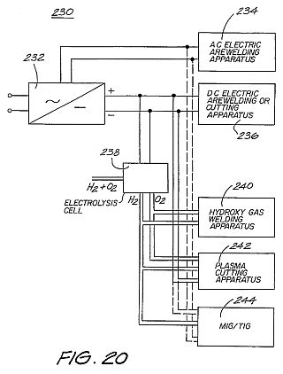

DETAILED DESCRIPTION AND BEST MODE OF PERFORMANCE
An electrolysis cell bank embodying the invention is constructed of a number of hexagonally shaped electrolysis cell plates 10, one of which is shown in plan a in FIG. 1a and as a side view in FIG. 1b. Each plate 10 has three slots 12, each one arranged in alternating side edges of the plate 10. The other sides of the cell plate 10 each are provided with a conductive bridge or flange 14. Typically twenty individual cell plates 10 are stacked to form one complete cell 16 as shown as a side view in FIG. 2. The total number of plates can vary in accordance with the required surface area, and thus, also is a function of plate diameter.
The stacking of adjacent individual cell plates 10 is in a reversed order, so that the conductive bridges 12 of adjacent plates extend in opposed directions and with a relative rotational offset of 60 DEG . This rotational offset is provided so that adjacent plates 10 are to bear opposite polarity. The conductive bridges 14 are long enough to pass through a corresponding slot 12 in an adjacent plate 10, without contacting that plate, and contact the next subsequent plate to form a conductive path between each alternate plate. In this way, the completed cell structure 16 has three positive end terminals and three negative end terminals, although FIG. 2 shows only two of the positive terminals and one of the negative terminals. The cell stack 16 is enveloped by an insulating case 18 (shown in cut-away form). The cell plates 10 shown in FIGS. 1a, 1b and 2 are suited to form in a parallel electrical arrangement, with each adjacent two cell plates 10 forming either the anode or the cathode.
Parallel stacked flat cell plates are described in Australian Patent No. 487062. In that patent, a stack of twenty cell plates typically requires a potential difference across the individual electrodes of each cell plate in the range of 1.55-2.0 volts to liberate hydrogen and oxygen gas from the water containing an electrolyte of typically 15% sodium hydroxide solution.
FIG. 3 shows, as a vertical cross-sectional view, seven complete cell stacks 16 arranged in a hexagonal matrix and enclosed by a steel casing 20, thereby to provide an electrolysis cell bank 25. The cell stacks 16 are insulated from the steel casing 20 by nylon insulating bushes 22. The electrical interconnection of the individual cell stacks 16 is not shown, but typically the cells are connected between their respective positive (+) and negative (-) terminals by straps to form a series connection.
It sometimes can be the case that a parallel interconnection of the cell stacks 16 is implemented. The actual electrical interconnection will depend upon the number of individual cell plates 10 comprising each cell stack 16, the supply voltage and the current that can be drawn from the supply.
Water is consumed as the hydrogen and oxygen gas is liberated during the electrolysis reaction. One liter of water generates 1860 liters of admixed oxygen and hydrogen at STP, in the volumetric proportion noted above. In the arrangement shown water is continually supplied through the inlet port 24.
The nylon covers 18 separating adjacent stacks have the benefit of directing the liberated gas upwardly to be collected by, for example, a gas outlet 26 located at the top of the electrolysis cell bank 25. By virtue of volumetric displacement in a ratio of 1:1860, the liberated gases are self-pressurizing as they pass from the outlet port 26 into the interconnecting pipe work (not shown), which has a far narrower cross-sectional area than that of the cell bank.
FIG. 4 is a vertical cross-sectional view showing the mechanical configuration of an electrolysis cell in accordance with a further embodiment. The basic cell unit 30 is constituted by respective halves of a pair of interdigitated electrodes 32, 34 arranged much in the nature of interleaved combs. Each electrode is formed by a conductive spine 36, 38, typically constructed of resin bonded carbon material, mild steel or conductive polymers, from which extend eleven finger-like plates 40, 42, also constructed of carbon, steel or conductive polymer.
FIG. 5 is a perspective view of one of the electrodes 32 in which the spine 36 and plates 40 are rectangular in shape. The electrodes need not necessarily be of the shape shown, but rather can take on many other forms, one example of which will presently be described. The common requirement for all such configurations is that the plates be parallel and interconnected by a common member usually arranged orthogonally to the plates.
Each pair of electrodes 32, 34 are in a staggered arrangement so that the respective outermost plates 40a, 42a are offset by approximately one half of the total length of each electrode 32, 34. The respective mid-point plates are identified by the reference numerals 40b and 42b.
FIG. 6 shows the staggering arrangement in a simplified form. Every sixth plate is located in the space formed between the first and eleventh plate of the respective opposed adjacent electrodes.
Referring to FIG. 4 again, two complete cell units 30 and a part of the next respective adjacent cell units are shown. The total number of cell units is governed by the DC supply voltage, since a minimum anode/cathode voltage is required to derive the electrolysis process, and each adjacent cell unit is in a series electrical connection of the parallel-arranged plates 40, 42. In the electrolysis process, the cells 30 are immersed in water and electrolyte and a DC voltage is applied between the end-most plates 40c, 42c causing elemental ionic currents (some of which are represented by the dashed arrows) to flow between the adjacent plates 40, 42, and some current-wise along the respective spines 36, 38 and plates 40, 42 (shown by the solid arrows). A different current path is followed at each mid-plate. For example, the DC current travels from one end cell plate 42a, through the electrolyte, passing through the mid cell plate 40b and again through the electrolyte to the next end cell plate 42a. This process causes the accumulation of net positive charge on one side of the mid-plate 40b, and a negative charge on the other side.
The ionic current flow is accompanied by disassociation of the water molecules such that oxygen and hydrogen gas is produced respectively at the anode plate and cathode plate surfaces. The cathode plate surfaces are those surfaces towards which ionic current flows. The converse applies for the anode plate surfaces.
The voltage applied across the end-most plates 40c is divided equally between the constituent cell units 30, with that fraction of the supplied voltage appearing between the respective outer-most plates and mid-point plates 40a & 42b, 40b & 42a.
The achievable current density is limited, in part, by the effective electrical resistance of the electrolytic solution. The smaller the gap between adjacent plates 40, 42 the less is the resistance. The interdigitated nature of the electrodes 32, 34 means that there is a large surface area available per unit volume, and there is a minimum separation between electrode plates in all instances. In that case, the resistance of the electrolyte is kept low, hence efficiency of the conversion of electrical energy to generate the hydrogen and oxygen gases is greater than in the prior art.
By virtue of the specific arrangement shown, it is not necessary to isolate each individual cell unit 30 from adjacent ones thereof. The ionic flow naturally will take the path of least resistance, hence short-circuits between cell units 30, being a path otherwise of greater resistance, are avoided. A large number of cells therefore can be arranged to extend longitudinally, and allow direct connection to a rectified mains power supply, thus obviating the need to electrically interconnect groups of cell units by strapping, as has been done in the prior art.
Each individual cell unit 30 satisfies the operational criteria regarding voltage, the surface area of the plates and so on, to successfully electrolyze water, and thereby operates essentially independently of the adjacent cell units 30.
Testing has established that for a temperature range of 90 DEG C. to 50 DEG C., a DC voltage in the range 1.47-1.56 V applied across one cell unit 30 (i.e. across one half of a complete electrode 32 or 34) a minimum (and the optimum) anode current density of 0.034 A/cm@2 is required to generate a gas flow rate of about 340-300 l/h per kWh respectively. The discovery that the minimum plate surface area corresponds to the optimum gas flow rate means that the total volume occupied can be kept to a minimum. By way of specific example, a rectified 240 Vrms main voltage nominally results in an average DC voltage of 215 V, hence for direct connection to the main supply via a rectifier (i.e. without requiring a step-down transformer), a total of about one hundred and forty cells are required. It is particularly advantageous not to require voltage transformation equipment in terms of equipment cost, technical simplicity and the avoidance of losses.
FIG. 7a shows a partial cut-away side view of a cell unit 50 in accordance with another embodiment. The cell unit 50 is similar in configuration to that of FIG. 4 except for the number and shape of interconnecting spine members and the shape of the electrode plates.
FIG. 7b shows an end view of the cell unit 50, and in particular the end-most plate 52c. The plate electrodes 52, 54 are hexagonal in shape. Each plate 52, 54 has six interconnecting rod-like spines 56, 58 passing therethrough, one near each vertice. Each alternate one of the spines 56 represents a common positive conductor and the other set of alternate spines 58 represents negative conductors. Each adjacent plate 52, 54 is electrically connected either to the positive conductors or the negative conductors. Spacing bushes 60 are provided between adjacent plates 52, 54 to provide electrical isolation and to provide a space in which the water and electrolyte circulates. Connection of each spine conductor 56, 58 to the respective plate electrode 52, 54 typically is by a threaded nut or interference fit. The reason for connecting each plate 52, 54 to three common spine conductors 56, 58 is to achieve a uniform current distribution across the whole surface area of a plate 52, 54.
As can be seen in FIG. 7b, the positive spine conductors 56 extend away from one end of the assembly for series interconnection with other arrangements of cells, as do three negative spine conductors 58 from the other end. All unconnected ends of the conductors are blanked-off with a non-conductive end cap 62.
FIG. 8 shows a stylized form of three cell units 50 electrically connected in series (arranged longitudinally), and particularly the passage of the spine conductors 56, 58. The cell units 50 are enclosed within an insulating tube 64, typically made of PVC, which has an access for the communication of water to envelope the plates 52, 54 and for the generated gases to escape.
FIG. 9 shows the series electrical interconnection of a number of cell units 50 directly connected with the DC output side of an AC/DC converter 66 (such as a simple diode bridge rectifier) without requiring a step-down transformer.
FIG. 10a shows an end view of the mechanical arrangement of seven assemblies (designated A-G), each consisting of three series connected cell units 50 (as shown in FIG. 8), forming a total cell arrangement 70. The cell assemblies 50 are located within a steel cylinder 72 containing the water and electrolyte required for the generation of the hydrogen and oxygen gases. Each group (A-G) of three cell units 50 is interconnected by means of a first group of steel connecting straps 74 at one end and a second group of steel connecting straps 76 (not shown) at the other end, arranged to be offset between the groups. While the first straps 74 alone are shown in FIG. 10a, both sets of the straps 74,76 are more clearly shown in FIG. 10b, which is a side view of the groups A-G when `unravelled`.
The PVC tubes 64 shown in FIG. 10a insulate adjacent groups to avoid "short-circuiting" effects between one another. The cell arrangement 70 is very compact, and in a comparison with the prior art Brown arrangement is only one third of the physical size for a comparable gas volumetric flow rate. Moreover, there also being a similar reduction in total mass. The supply of water for the electrolysis process is provided by an inlet 78 located at the bottom of the cylinder 72, with the gases produced exit the cylinder 72 by an outlet 80 located at the top of the cylinder.
Electrical connection to a DC power supply is across the totality of the cells, and in the arrangement is at a central terminal 82 on the underside of cell A and a central terminal 84 on the top side of cell G, respectively.
FIGS. 11a and 12a show further embodiments of a first and second type of cell plate 90, 98 as an end view. FIGS. 11b and 12b are partial cross-sectional views along the respective mid-lines as shown. Common reference numerals have been used where appropriate. The plates 90, 98 can have the function of either an anode (+) or a cathode (-), as will become apparent. Each comprises an electrode disc 92 that is perforated with hexagonally shaped holes 96. The disc 92 is made from steel or resin-bonded carbon or conductive polymer material. The disc 92 is housed in a circular rim or sleeve 94. The function of the perforations 96 is to maximize the surface area of the electrode disc 92 and minimize the weight over solid constructions by 45%.
By way of example, for a disc having diameter of 280 mm, the thickness of the disc must be 1 mm in order to allow the current density (which ranges from 90 A/2,650 cm@2 -100 A/2,940 cm@2 of the anode or cathode) to be optimal. If the diameter of the plate is increased, which consequently increases the surface area, it is necessary to increase the thickness of the plate in order to maintain uniformity of conductance for the desired current density.
The hexagonal perforations in a 1 mm thick disc have a distance of 2 mm between the flat portions of the plates and are 1 mm away from the next adjacent perforation, in order to maintain the same total surface area prior to perforation, and to allow the current density to be optimal. A 1 mm (plate to plate) distance between the adjacent hexagonal perforations is required because a smaller distance will result in thermal (resistive) losses and a larger distance will add to the overall weight of the plate.
The sleeve 94 is constructed of PVC material and incorporates a number of equally spaced shaft holes 100, 102. The holes are for the passage of interconnecting shafts provided in a stacked arrangement of the plates 90, 98 forming the common conductor for the respective anode and cathode plates, much in the nature of the arrangement shown in FIGS. 7a and 7b. The additional two upper holes 104, 106 each support a conduit respectively for the out-flow of oxygen and hydrogen gases, respectively. The additional holes 108, 110 at the bottom of the sleeve 94 are provided for the inlet of water and electrolyte to the respective cell plates 90, 98.
FIG. 13 shows an enlarged view of a portion of the cell plate 90 shown in FIG. 11a. The port hole 104 is connected to the hexagonal perforations 96 within the sleeve 94 by an internal channel 112. A similar arrangement is in place for the other port hole 106, and for the water/electrolyte supply holes 108, 110.
If the hydrogen and oxygen gases liberated are to be kept separate (i.e. not to be formed as an admixture), then it is necessary to separate those gases as they are produced. In the prior art, this is achieved by use of diaphragms that block the passage of gases and effectively isolate the water/electrolyte on each side of the diaphragm. Ionic transfer thus is facilitated by the ionically conductive nature of the diaphragm material (i.e. a water--diaphragm--water path). This results in an increase in the ionic resistance, and hence, a reduction in efficiency. Prior art patent No. 487062 describes another arrangement (see FIG. 6 thereof) that utilizes magnets to cause the separation of the gases.
FIG. 14 shows an exploded stacked arrangement of four cell plates, being an alternative stacking of two (anode) cell plates 90 and two (cathode) cell plates 98. The two ends of the stacked arrangement of cell plates delineates a single cell unit 125. Interposed between each adjacent cell plate 90, 98 is a PTFE separation 116. Although not shown in FIG. 14, the cell unit includes separate hydrogen and oxygen gas conduits that respectively pass through the stacked arrangement of cell plates via the port holes 106, 104 respectively. In a similar way, conduits are provided for the supply of water/electrolyte, respectively passing through the holes 108, 110 at the bottom of the respective plates 90, 98.
Only two pairs of anode/cathode cell plates are shown. The number of such plates can be greatly increased per cell unit 125.
Also not shown are the interconnecting conductive shafts that electrically interconnect alternate common cell plates. The reason for having a large diameter hole in one cell plate adjacent to a smaller diameter hole in the next cell plate, is so that an interconnecting shaft will pass through the larger diameter hole, and not make an electrical connection (i.e. insulated with PVC tubing) but rather only form an electrical connection between alternate (common) cell plates.
The cell unit 125 shown in FIG. 14 arrangement is an exploded view. When fully constructed, all the elements are stacked to be in intimate contact. Mechanical fastening is achieved by use of one of two adhesives such as (a) "PUR-FECT LOK" (TM) 34-9002, which is a Urethane Reactive Hot Melt adhesive with a main ingredient of Methylene Bispheny/Dirsocynate (MDI), and (b) "MY-T-BOND" (TM) which is a PVC solvent based adhesive. Both adhesives are Sodium Hyroxide (20% present in the electrolyte) resistant. In that case, the water/electrolyte only resides within the area proscribed by the cell plate sleeve 94. Thus the only path for the inlet of water/electrolyte is by bottom channels 118, 122 and the only outlet for the gases is the top channels 112,120. In a system constructed and tested by the inventor, the thickness of the cell plates 90, 98 is 1 mm (2 mm on the rim because of the PVC sleeve 94), with a diameter of 336 mm. The cell unit 125 is segmented from the next cell by an insulating PVC segmentation disc 114. A segmentation disc 114 is also placed at the beginning and end of the entire cell bank.
If there is to be no control over separation of the liberated gases, then the PTFE membranes 116 are not needed.
The PTFE membrane 116 is fibrous and has 0.2 to 1.0 micron interstices. A suitable type is type Catalogue Code J, supplied by Tokyo Roshi International Inc (Advantec). The water/electrolyte fills the interstices and ionic current flows only via the water--there is no contribution of ionic flow through the PTFE material itself. This leads to a reduction in the resistance to ionic flow. The PTFE material also has a "bubble point" that is a function of pressure. Hence by controlling the relative pressures at either side of the PTFE separation sheets, the gases can be "forced" through the interstices to form an admixture, or otherwise kept separate. Other advantages of this arrangement include a cheaper cost of construction, improved operational efficiency and greater resistance to faults.
FIG. 15a is a stylized and exploded, schematic view of a linear array of three series-connected cell units 125. For clarity, only six interconnecting shafts 126-131 are shown. The shafts 126-131 pass through the respective shaft holes 102, 100 in the various cell plates 90, 98 in the stacked arrangement. The polarity attached to each of the exposed end shafts, to which the DC supply is connected also is indicated. The shafts 126-131 do not run the full length of the three cell banks 125. The representation is similar to the arrangement shown in FIGS. 7a and 8. One third of the full DC source voltage appears across each anode/cathode cell plate pair 90, 98.
Further, the gas conduits 132, 133, respectively for oxygen and hydrogen, that pass through the port holes 104, 106 in the cell plates 90, 98 also are shown. In a similar way, water/electrolyte conduits 134, 135, passing through the water port holes 108, 110 in the cell plates also are shown.
FIG. 15b particularly shows how the relative potential difference in the middle cell bank 125a changes. That is, the plate electrode 90a now functions as a cathode (i.e. relatively more negative) to generate hydrogen, and the plate electrode 98a now functions as an anode (i.e. relatively more positive) to generate oxygen. This is the case for every alternate cell unit. The arrowheads shown in FIG. 15b indicate the electron and ionic current circuit. FIG. 15c is an electrical equivalent circuit representation of FIG. 15b, where the resistive elements represent the ionic resistance between adjacent anode/cathode plates. Thus, it can be seen that the cell units are connected in series.
Because of the change of function of the cell plates 90a and 98a, the complementary gases are liberated at each. Hence, the respective channels 112 are connected to the opposite gas conduit 132,133. Practically, this can be achieved by the simple reversal of the cell plates 90, 98.
FIG. 16 shows the three cell units 125 of FIG. 15a connected to a gas collection arrangement. The cell units 125 are located within a tank 140 that is filled with water/electrolyte to the level h indicated. The water is consumed as the electrolysis process proceeds, and replenishing supply is provided via the inlet 152. The water/electrolyte level h can be viewed via the sight glass 154. In normal operation, the different streams of oxygen and hydrogen are produced and passed from the cell units 125 to respective rising columns 142,144. That is, the pressure of electrolyte on opposed sides of the PTFE membranes 116 is equalized. Thus, the gases cannot admix.
The columns 142, 144 also are filled with the water/electrolyte, and as it is consumed at the electrode plates, replenishing supply of electrolyte is provided by way of circulation through the water/electrolyte conduits 134, 135. The circulation is caused by entrainment by the liberated gases, and by the circulatory inducing nature of the conduits and columns.
The upper extent of the tank 140 forms two scrubbing towers 156, 158, respectively for the collection of oxygen and hydrogen gases. The gases pass up respective columns 142, 144, and out from the columns via openings therein at a point within the interleaved baffles 146. The point where the gases exit the columns 142, 144 is beneath the water level h, which serves to settle any turbulent flow and entrained electrolyte. The baffles 146 located above the level h scrub the gas of any entrained electrolyte, and the scrubbed gas then exits by respective gas outlet columns 148, 150 and so to a gas receiver. The level h within the tank 140 can be regulated by any convenient means, including a float switch, and with the replenishing water supplied by the inlet pipe 152.
The liberated gases will always separate from the water/electrolyte solution by virtue of the difference in densities. Because of the relative height of the respective set of baffles, and due to the density differential between the gases and the water/electrolyte, it is not possible for the liberated hydrogen and oxygen gases to mix. The presence of the full volume of water within the tank 140 maintains the cell plates in an immersed state, and further serves to absorb the shock of any internal detonations should they occur.
In the event that a gas admixture is required, then, firstly, the two flow valves 136, 137 respectively located in the oxygen gas outlet conduit 132 and water/electrolyte inlet port 134 are closed. This blocks the outlet path for the oxygen gas and forces the inlet water/electrolyte to pass to the inlet conduit 134 via a one-way check valve 139 and pump 138. The water/electrolyte within the tank 140 is under pressure by virtue of its depth (volume), and the pump 138 operates to increase the pressure of water/electrolyte occurring about the anode cell plates 90, 98a to be at an increased pressure with respect to the water/electrolyte on the other side of the membrane 116. This pressure differential is sufficient to cause the oxygen gas to migrate through the membrane. Thus, admixed oxygen and hydrogen are liberated via the gas output conduit 133 and column 144. Since there is no return path for the water/electrolyte supplied by the pump 138, the pressure about the cell plates 90, 98a will increase further, and to a point where the difference is sufficient such that the water/electrolyte also can pass through the membrane 116. Typically, pressure differential in the range of 1.5-10 psi is required to allow passage of gas, and a pressure differential in the range of 10-40 psi for water/electrolyte.
While only three cell units 125 are shown, clearly any number, connected in series, can be implemented.
FIG. 17 shows another embodiment of a check valve and scrubber unit 160 for scrubbing liberated gas(es) before subsequent use. The unit 160 is filled with water, typically to a level being about half the full height of the unit. The level is regulated by a float switch 162. Water is supplied by means of the inlet 164. A sight column 166 is also provided, which serves to give a visual indication of the water level.
The hydrogen and/or oxygen gases from the gas receiver, now under pressure, enter by an entry tube 168 having an opening 170 at the bottom end thereof. The gases travel down the tube 168 and out of the opening 170 to bubble upwardly on the inside of the inner column 172, which also is filled with the supplied water, thus performing a first scrubbing action to remove the sodium hydroxide electrolyte. The gas then enters another downwardly directed tube 174 and out the opened end thereof, passing again through the water in the outer chamber 176 to be further scrubbed. The gas is to be stored under pressure within the space above the water level and be available for supply from the outlet 178.
Admixed hydrogen and oxygen gases supplied from the output 178 to, for example, a welding tip (not shown) are in the correct stoichiometric proportions as a result of the electrolysis process, and ensures that, on combustion, a neutral flame is produced. The only products of the combustion process are heat and water vapour.
If the gases are produced separately, two check-valve scrubbers 160 are employed, the gases can then be mixed in a mixing chamber which also will produce the correct stoichiometric mix.
If there is an explosion which backs-up through the outlet 178 from a welding tip, it will be quenched by the water within the unit 160. The energy of the explosion will be absorbed by displacing the water in both the outer chamber 176 and the inner column 172. This displacement also cuts off the flow of inlet gas to the tube 168. In this way, there will be no possibility of the explosion further propagating towards an electrolysis cell bank producing the gases. The water within the unit 160 therefore acts both as a gas scrubber and also as a check valve.
FIG. 18 shows a welding tip 180 in cross-sectional detail. The hydrogen and oxygen gases are received along an inlet tube 182, passing by a needle valve 184 and into an expansion chamber 186. The expansion chamber 186 includes a flashback control apparatus, which comprises a cylindrically arranged flashback arrester 188, typically formed of 5 micrometer stainless steel meshing. In normal operation, the gases flow through the flashback arrester 188 and to the outlet or nozzle 190, where combustion, or gas ionisation during the production of plasma, takes place.
In the event that flashback occurs, the flashback arrester 188 disallows further rearward passage of the flame, which cannot physically pass through openings as small as, for example, 5 micrometers. This is coupled with a heat sink effect of the material from which the arrester 188 is constructed which operates to dissipate the energy of the flame, and thus, assist in extinguishing the flame.
The use of hydrogen and/or oxygen in welding and cutting by electrolysis allows temperatures of the order of 6000 DEG C. to be achieved with the ability to produce gas on demand. No gas stored in bottle form is required. It is further possible to conduct fine flame welding with a high purity of gas, and also to be able to fuse ceramic materials.
All of the following materials can be welded: carbon steel, cast iron, stainless steel, aluminium, brazing, silver soldering, copper and ceramics. The following ferrous and non-ferrous materials, due to the available production of pure hydrogen subsequently passed through a DC arc providing a hydrogen plasma stream (H2 .fwdarw.H1), can be readily cut: carbon steel, cast iron, stainless steel, aluminium, brazing and copper.
The embodiment of the invention can provide a continuous supply of hydrogen gas at large flow rates. As such, it is well disposed to applications that consume large quantities of hydrogen. An example of one such process is the Plascon (TM) waste destruction process developed by the Australian CSIRO's Division of Manufacturing Technology. A summary of the Plascon process can be found in the CSIRO Journal "Ecos, Volume 68, Winter 1991".
One application of the hydrogen and oxygen gases produced by the apparatus described above is in the thermal destruction of waste, and without the consumption of atmospheric oxygen. This procedure requires an on-demand supply of hydrogen and oxygen gas. The electrolysis apparatus described above can, in a scaled-up version, produce the requisite gas flow rates in order to combust waste gases on a commercial scale.
FIGS. 19a and 19b show a configuration for a burner used in the destruction of such gaseous polluting emissions. FIG. 19a shows a cross-sectional view of a burner 200. The cross-sectional view along the mid-line is shown in FIG. 19b. The burner 200 has a combustion chamber 202 that is hemispherical in shape. The emissions, which may include a mixture of fumes containing hydrocarbons and other volatile pollutants as a waste product of industrial processes, are injected to the combustion chamber by an inlet path 206. There are two sources of an admixture of gaseous hydrogen and oxygen in stoichiometric proportions of 2:1, one each to an upper and lower quadrant of the combustion chamber 202. These gases are supplied by the two gas inlets 208 at points diametrically opposed on the sides of the burner 200. The mixture of hydrogen and oxygen and emissions formed within the combustion chamber 202 is ignited by means of a spark plug 210, or the like, and burns at a temperature of not less than 4000 DEG C., thus providing energy for molecular disassociation of all the pollutants into harmless compounds that can be discharged to the atmosphere. No atmospheric oxygen is consumed in the burning process. Complete combustion of the pollutants is aided by the "focusing" effect of the combustion chamber 202, which further improves the mixing of the gas streams.
A thermocouple 212 measures the temperature within the silicone fiber refractory heat insulatory material 214 surrounding the combustion chamber 202. The cladding 216 applied to the burner 200 is typically made of stainless steel.
The burner configuration is formed by seven (only four are shown) concentrically arranged sets of nozzles 212, as is clearly shown in FIG. 19b. The nozzles 222 are directed to commonly intersect at the epicenter 204 of the combustion chamber 202. The cooling water, supplied by an inlet 218 and exiting by an outlet 220, is intended to maintain the nozzles 222 at a temperature of less than 300 DEG C. Above 300 DEG C., hydroxy gas has the tendency to "back burn".
The flow path of hydrogen and oxygen gases to the nozzles 222 from the inlets 208 has four 90 DEG (minimum) correction changes. This is intended to slow the linear momentum of the hydroxy flame in the event of a flashback, and so cause the flame to self-extinguish. This is particularly advantageous, as hydrogen burns at a rate of 3,600 m/s.
FIG. 20 shows in block diagram form a multi-modal cutting and welding apparatus 230. The apparatus receives a supply of DC power provided to an AC/DC converter 232. An AC supply is available for connection to AC electric arc welding apparatus 234, while the converted DC output voltage is provided for connection with a DC electric arc welding or cutting apparatus 236. The DC output supply voltage also is provided to an electrolysis cell unit 238 for the generation of, in this case, separated hydrogen and oxygen gases. The hydrogen and oxygen gases both are provided to a hydroxy gas welding apparatus 240. The hydrogen (and oxygen for secondary injection) is made available for connection with plasma cutting apparatus 242. The hydrogen is passed through a DC arc to produce a plasma stream, and on a secondary injection, the oxygen is introduced into the plasma stream to produce an oxidizing plasma cutting effect which increases cutting efficiency. Thicknesses of up to 150 mm can be cut with this process. It should be noted that introducing oxygen downstream from the tungsten electrodes eliminates any oxidation of the electrodes.
The hydrogen gas alone also is provided to a MIG/TIG apparatus 244, with the hydrogen in plasma form otherwise taking the place of the conventional inert gas. An AC or DC supply also is required to form the plasma.
The converter 232 can be of any conventional design, typically having a multi-tapped transformer for the selection of appropriate rectified DC voltages. The electrolysis unit 238 can be of any of the embodiments previously described, and including the scrubber and check valve arrangements. The various cutting and welding apparatus 234, 236, 240, 242, 244, described also are conventional.
The multi-modal apparatus 230 thus provides greater flexibility for the user in being able to select from the one unit the particular mode of cutting or welding required. Clearly, an apparatus comprised of any single or combination of welding/cutting apparatus is contemplated by the present invention.
FIG. 21 shows the multi-modal apparatus 230 in greater detail. As previously described, the electrolysis generator 238 separately produces gaseous hydrogen and oxygen and can also produce gaseous hydrogen and oxygen as an admixture.
The power supply unit 232 comprises a multi-tapped transformer 246. The reduced voltage is rectified by a bridge rectifier 247. The output rectified voltage is then connected by terminals 248 to the cell bank 238 containing 30 cells via a contactor 249 which is activated by a pressure switch 250. The switch 250 is, in turn, activated by a pressure sensor 251 which measures the gas pressure levels within the cell bank 238. Thus the contactor 249 is operable to remove the supply of power to the cell bank 238 on the establishment of an operational pressure. The contactor 249 operates on demand with use of the gas.
Thus, gas is produced as required, and typically for a total of 15 liters at any one time. This 15 liters of gasses comprises 10 liters of hydrogen and 5 liters of oxygen.
The gases are provided from the scrubbing towers 156, 158 of the cell bank 238. As a closed loop system, the pressure in each tower will compensate for the other, thereby maintaining constant desired gas production levels. If, however, the water level is too high due to excessive use of either gas, the respective float switch 254, 255 in the respective tower 156, 158 will disallow gas flow by shutting the respective solenoid valve 256, 257.
The float switches 254, 255 activate the solenoid valves 256, 257 from an AC supply 258 tapped from the transformer 246. Other float switches located in the check valve and scrubber units 160 and the pressuring pump 138, also receive the AC supply 258.
Two flow regulators 261, 262 are incorporated for the purpose of maintaining the desired back-pressure in the towers 156, 158 in order that the system will always have pressure even if the system is switched off and/or should the gases be exhausted through gas outlets, the gas outlets 263, 264 of the check valves/scrubber units 160 or by the welding tip 265.
As opposed to separated generation in the cell bank 238, method of obtaining an admixture is once the hydrogen and oxygen have passed through the check valve and scrubber units 160, a selection valve 266 allows the gases to mix and pass to the welding tip 265 where they are ignited and combusted to be used for the purposes of hydrogen/oxygen welding.
If the hydrogen and oxygen gases are produced separately and required for hydrogen plasma cutting 242 and/or hydrogen plasma MIG/TIG welding 244, the selection valve 266 disallows the admixture of the two gases.
The power supply unit 232 is a conventional arrangement of a multi-tapped transformer 246, including a reactor winding 267 and a range selector switch 268 which allows a selection of a chosen output voltage level. The generated secondary AC voltage also can be rectified by the rectifier 247 to produce a DC voltage output. All these output voltages pass another polarity selector 269 allowing the user to select between an AC or DC output and to select the appropriate polarity for the DC output.
The output 248 from the power supply unit 232 is shown connected to the electrolysis cell bank 238. However, the power supply also can connect with other forms of welding and cutting such as indicated in FIG. 20.
Another output 271 supplies the necessary DC power for hydrogen plasma shroud MIG/TIG welding 244 and hydrogen plasma oxidising cutting applications 242. Yet another AC output 272 and DC output 273 supply the necessary current to produce an arc for the MIG and TIG processes.
Output voltages in the range of 20-60 Volts are required for the cell bank unit 238 and the electric arc units 234, 263, whereas the MIG/TIG welding 244 operates, typically, on an output voltage of 30-60 Volts (AC or DC). Plasma cutting and plasma shrouding, as provided by the plasma unit 242, typically requires the supply of 120 Volts DC.
UPDATING
OF ELECTROLYSIS SYSTEMS
RU2149921
RU2149921
FIELD: chemistry.
SUBSTANCE: cellular device has complex structure composed of separating discs, cellular plates of first type ( anode ), cellular plates of second type ( cathode ) and separating membranes. Joining conductive rods pass through holes in cellular plates to perform selective electric connection. Water and electrolyte for submersion of cellular plates are supplied through inlets holes. Normally membranes isolate adjacent plates-cathodes and plates-anodes from mixing released gaseous oxygen and hydrogen and provide for flow of ion current.
EFFECT: enhanced efficiency of conversion of electric energy.
DESCRIPTION
The present invention relates to the formation of hydrogen gas and oxygen gas from water, either as mixtures or as separated gases using an electrolysis process, and also relates to applications associated with the released gas.
Embodiments of the invention, in particular, to an apparatus for the efficient production of these gases and to use these gases as a heat source in atomic welding or cutting, and to eliminate gaseous losses.
Well known water electrolysis method in the presence of an electrolyte such as sodium hydroxide (NaOH) or potassium hydroxide (KOH) with the release of hydrogen and oxygen gases (H, O).
The process involves application of the potential difference Vdc between two or more anode / cathode electrode pairs and supplying the minimum energy required to break bonds HO (ie
68.3 kcal / mol at normal conditions).
Gases produced in the stoichiometric proportions for O: Hb 1:2 respectively allocated at the anode (+) and the cathode (-).
You can refer to the following articles: "Modern Electrochemistry, v.2, John O'M. Bockris and Amulya KN Reddy, Plenum Publishing Corporation "," Electro-Chemical Science, J. O'M Bockris and DM Drazik, Taylor and Francis Limited "and" Fuel Cells, Their Electrochemistry, J. O'M. Bockris and S. Srinivasan, McGraw-Hill Book Company ".
Discussion of the experimental work in relation to the electrolysis process can be found in the "Hydrogen Energy, Part A, Hydrogen Economy Miami Energy Conference, Miami Beach, Florida, 1974, edited by T. Nejat Veziroglu, Plenum Press".
Particularly relevant is the article submitted J. O'M. Bockris on p.371-379, FC Lensen and FH Schubert on p. 425-439 and B. Pangborn and John C. Sharer on p.
499-508.
By and large, the quantity of gas dependent on a number of variables, including the type and concentration of the electrolytic solution, the surface area of ??the anode-cathode electrode pair, the electrolytic resistance (equal to the ion conductivity which is a function of temperature), the achievable current density and the potential difference between the anode and cathode.
The total energy supplied shall be sufficient for the dissociation of water and ions formation of hydrogen and oxygen gases, but it is necessary to avoid coating (oxidation / reduction) metallic or non-metallic conductive materials making up the electrodes.
One can refer to the prior Australian Patent N 487062 website Yull Brown, which discloses construction of an electrolytic cell for producing hydrogen and oxygen as needed, together with a safety device to prevent pressurisation of evolved gases.
FIG. 2 Brown patent shows a plurality of electrodes (20a, 20b) electrically connected in series between two terminals (22) to which a potential difference is applied.
Box (20) provides a flow rate of gas at the outlet, and when this capacity is insufficient for a particular application, then a larger number of individual cellular devices that are electrically connected in series.
The end result is a great design that you want to maintain.
Also it is not possible to achieve the required high volumetric gas flow velocities (about 10,000 l / h) from the previously known devices without the use of expensive and sophisticated equipment, but even then the equipment has a low conversion efficiency of electrical energy to produce hydrogen and oxygen gases.
Thus, the commercial application of such devices High resolution is not economically feasible.
Mixed gas of hydrogen and oxygen (or hydroxy gas) are used as heat source in the combustion in the stream, such as furnaces.
For cutting atomic hydrogen is only one and often - for atomic welding, although disclosed in Brown apparatus performs welding in the presence of atomic hydrogen and oxygen mixed.
Modern industrial practice clearly confirmed that the presence of oxygen in the plasma arc causes intense oxidation of tungsten electrodes.
One of the problems that occur during the use of these applications is the need to combine the electrical switchgear to transform the voltage to a suitable level for a block of electrolytic cells (i.e. by step-down transformers).
Completed final design is inefficient, from an electrical point of view, and cumbersome and can be expensive if fine adjustment of voltage and current (and hence, the regulation of the gas flow).
Combustible gaseous hydrogen and oxygen mixed into a single stream, burn at very high temperatures, typically of the order 6000C. Hydrogen / oxygen welding devices are well known and consist of a welding tip or hand portion connected to the dual gas hose to separate feeding of oxygen and hydrogen.
There are four other known types of welding apparatus and methods of their application - it is the oxygen-acetylene welding, electric arc welding system MIG (metal inert gas) / TIG (tungsten-inert gas) and plasma cutting.
It is estimated that in use in Australia are more than 100,000 oxy-acetylene units.
Of these, approximately 70% are used primarily for cutting, and the remaining are used as heat sources for welding fusing sheet metal, brazing, silver soldering, etc.
Usually oxygen-acetylene welding metal settings can thickness from 0.5 to 2 mm.
Additionally, metal can be cut up to 140 mm thick, but only if the steel contains a high percentage of iron.
The reason for this is that the iron and oxygen required to sustain the process of oxidation, which causes the effect of cutting.
Acetylene gas creates an initial temperature to start the oxidation reaction is usually equal to 850C. Oxy-acetylene cylinders require installation of gases (oxygen and acetylene), and hence the cylinders shall be purchased or rented, and then constantly maintained in good condition and using refilled.
Arc welding is a method used for welding metals more than 1.5 mm thick.
The principle is that the hand piece is supplied with a consumable electrode and the working electrode forms the other part.
Between the electrodes creates a potential difference of AC or DC, thereby causing arcing that manual portion is brought into an area close to the working part.
The arc can be used for melting or welding together of metal parts.
Systems MIG (metal inert gas) based on the continuous wire feed system.
In one known construction the consumable wire is surrounded by argon gas (or plasma), which is usually fed from a cylinder.
TIG (tungsten inert-gas) systems, on the other hand, require a weld wire that has to be entered manually into the welding area.
MIG / TIG-welding of the metal thickness can be from 1 to 20 mm, a typical stainless steel, aluminum, mild steel, etc.
References concerning plasma MIG-process can be made to the text of "The Science and Practice of Welding, v.2, AC Davies, Cambridge University Press ".
Plasma cutting is a cutting manner by means of compressed air (comprising predominantly nitrogen) to a DC electric arc, thereby creating a very high temperature (about 15000C), and thus taking the electrons from the nitrogen nucleus to form a high temperature plasma.
This plasma can be used for cutting iron and zhelezonesoderzhaschih materials such as mild steel, stainless steel, copper, brass and aluminum.
Applied plasma cutters can cut the material to 25 mm thickness and have the advantage that they require no use of a gas cylinder, and the normal air.
Reference to a plasma cutting can be done on the text "Gas Shielded Arc Welding, NJ Henthorne and RW Chadwick Newnes Technical Books".
As follows from the discussion of the prior art, no one unit or system is unable to perform all welding and cutting functions, and typically one of the systems described above must be given preference to any other particular operation.
This in turn requires that workers on metal or other metal industries industrial manufacturers bought and maintained in many different types of welding machines, in order to be able to do any work required.
Costs associated with the purchase of gas in cylinders for replacement, are also very high.
A preferred aim of the present invention is to provide a construction whereby the hydrogen and oxygen gases can be produced electrolytically, which lacks one or more of the aforementioned disadvantages.
In this sense, the electrolytic apparatus is compact and offers greater efficiencies than the prior art devices, the gas at comparable costs.
Another preferred object of the present invention is to provide an improved structure of an electrolytic cell for use in the production of hydrogen and oxygen.
The electrolytic cell can be used in a hydrogen / oxygen hydrogen welding or plasma cutting.
Other applications may include industrial processes that require sources from burning fuels such as furnaces for calcining and burning intractable wastes.
Another preferred object of the present invention is to provide an electrolytic cell structure which provides a selectable division or mixing gases of hydrogen and oxygen in a single gas stream.
The present invention is further directed to a predominantly single welder that can satisfy all user requirements for welding or cutting.
The advantage is that the cylinders do not require the presence of hydrogen or oxygen.
Cylinders is also not required by any other gas such as argon, in the systems of MIG / TIG immersion in an inert gas.
Another preferred object of the present invention is to provide a damper for a reverse flame hydrogen / oxygen welding or cutting tip hydrogen plasma.
Therefore, the invention discloses a honeycomb structure for the electrolysis of water to liberate hydrogen and oxygen gas.
Said structure comprises a plurality of electrodes, anodes in a folded state, each anode electrode comprises a flat plate through which pass one or more common first current conducting connecting elements
and a plurality of electrodes, the cathode in folded condition, each cathode electrode comprises a flat plate, through which undergo one or more common second conductive interconnecting current elements; in
the above structure, the electrodes and the electrodes are anodes, cathodes overlap.
The invention further discloses a cell structure for the electrolysis of water to liberate hydrogen and oxygen gas.
Said structure comprises a plurality of electrodes-anodes interconnected via one or more common first current conducting elements connected electrically in parallel; electrodes, anodes, a plurality of electrodes overlapped cathodes interconnected via one or more common second current conducting elements connected electrically in parallel; said electrodes, anodes and cathodes electrodes forming a cellular device, and a plurality of cellular devices connected electrically in series.
The invention further discloses a cell structure for the electrolysis of water to liberate hydrogen and oxygen gas.
Said structure comprises a plurality of anode electrodes, united in the folded structure, each anode electrode comprises a flat plate through which passes one or more common first conductive interconnecting element current; a plurality of cathode electrodes, united in a linear folded spatial structure, each cathode electrode comprises a flat plate through which pass one or more common second conductive interconnecting element current; in the above structure, the electrodes and the electrodes are anodes, cathodes overlap; and a plurality of membranes, each membrane located between adjacent anode electrode and cathode electrode, the membranes allow the passage of ionic current between adjacent electrodes, the anodes and cathodes, electrodes, but selectively blocking the flow of gas passing in dependence on the pressure difference between opposite sides of the membrane
The invention further discloses a device for releasing electrolytically gaseous pollutants.
The apparatus comprises a plurality of electrodes, anodes, overlapping a plurality of electrodes, cathodes; many separation membranes between each adjacent anode electrode and cathode electrode; means for supplying at least water to the anode electrodes and the cathode electrodes; said supply means to be operable to control the differential pressure of water at least on opposite sides of each membrane to provide a separation or selection of mixing the released gaseous oxygen and hydrogen.
The invention further discloses a structure of an apparatus for combustion thermal decomposition of gaseous pollutants.
The device comprises a hemispherical combustion chamber; supplying hydrogen gas and oxygen into the combustion chamber via a tortuous path, exiting through a plurality of concentrically arranged nozzles directed towards the epicenter of the hemispherical chamber; an inlet for the supply of gaseous pollutants; Combustion apparatus in the gaseous pollutants are burned with the gases (hydrogen and oxygen).
The invention also discloses a multimodular cutting and welding generator comprising a power source adapted for providing a plurality of output voltages AC and DC; electrolytic device connected to a power source for production of hydrogen and optionally oxygen alone or as a mixture of hydrogen and oxygen by water electrolysis using the constant voltage supplied from the power source; Hydrogen, oxygen, and hydrogen and oxygen mixed with an output voltage source suitable for connection to the welding apparatus and / or cutting.
The invention also discloses a damper for a reverse flame welding tip, is used when the combustion gas contains a quencher mesh barrier to the flow of gases to be incinerated, has a grid barrier clearances for ensuring the free passage of gases but prevent the reverse passage of flame, flame converse without being able to pass through the barrier, thus extinguished.
FIG. 1a and 1b depict a honeycomb plates in plan and side view respectively.
FIG. 2 shows a set of cellular folded plates.
FIG. 3 is a vertical sectional view of an electrolytic cell unit.
FIG. 4 is a vertical section showing arrangement of electrodes of part of another electrolysis cell block embodying the invention.
FIG. 5 shows a perspective view of part of one electrode shown in FIG. 4.
FIG. 6 shows a simplified representation of a sequence of electrode structure shown in FIG. 4.
FIG. 7a and 7b show the mechanical connection of one group of cells in another embodiment.
FIG. 8 illustrates the interconnection of several groups of cells as shown in FIG. 7a and 7b.
FIG. 9 shows a sequential electrical connection of several cells in a block of groups of cells.
FIG. 10a and 10b show the mechanical construction of the device unit cell.
FIG. 11a and 11b depict another embodiment of the honeycomb plate.
FIG. 12a and 12b illustrate the plate complementary to the cells of FIGS. Cells 11a and 11b.
FIG. 13 shows details of the perforation plate and part of the honeycomb shown in FIG. 11a, 11b, 12a and 12b.
FIG. 14 shows a discontinuity in the folded honeycomb plates of FIGS. 11a, 11b, 12a and 12b.
FIG. 15a schematic view of a gas separation system of FIG. 14.
FIG. 15b shows a stylized representation of FIG. 15a.
FIG. 15c shows an electrical equivalent circuit of FIG. 15a.
FIG. 16 shows a gas collection system for use with a unit cell separation system shown in FIG. 14 and 15a.
FIG. 17 depicts a cross-sectional hydraulic scrubber (scrubber) and the valve stopper.
FIG. 18 depicts a cross-sectional welding tip used with the equipment shown in FIG. 10 including the quencher reverse flame.
FIG. 19a and 19b shows a decomposition furnace combustion of polluting gases.
FIG. 20 shows a block diagram of multimodular welding and cutting device.
FIG. 21 is a schematic diagram of the apparatus shown in FIG. 20.


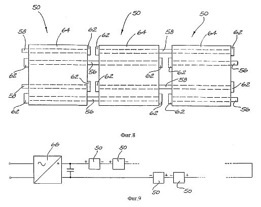


Detailed description of the invention.
Block electrolytic cell embodying the invention consists of several electrolytic honeycomb hexagonal plates 10, one of which is shown in plan in FIG. 1a and in side view in FIG. 1b.
Each plate 10 has three slots 12, each of which is located on the end sides of alternating plate 10.
Other side of each mesh plate 10 provided with a conductive bridge or flange 14.
Typically twenty individual cell plates 10 are combined into one set to form a completed cell 16 is shown in side view in FIG.
2. Total number of plates can vary in accordance with the desired surface area and is therefore also a function of the diameter of the wafer.
Combining a set of adjacent mesh plates 10 is carried out in a different order so that the conductive bridges 12 of adjacent plates extending in opposite directions and with a relative rotation of 60.
Said rotation is due to the fact that adjacent the plate 10 must be of opposite polarity.
The conductive bridges 14 are long enough to pass through a corresponding slot 12 in the adjacent plate 10, without contact with this plate and so as to contact with the next successive plate, forming a conductive path between each alternate plate.
Thus, filled cellular structure 16 has three positive and three negative output output, although FIG. 2 shows only two positive and one negative output conclusion.
Cellular set 16 surrounded by an insulating housing 18 (shown in cracked form).
Mesh plate 10 shown in FIG. 1a, 1b and 2 are suitable for forming a parallel electrical connection with each adjacent two cell plates 10 forming either the anode or cathode.
Parallel folded flat cell plates are described in Australian Patent N 487062.
It set of twenty cell plates typically requires a potential difference between the electrodes of each individual mesh plates in the range of 1.55-2.0 V for release of gaseous hydrogen and oxygen from water containing an electrolyte of typically 15% sodium hydroxide solution.
FIG. 3 depicts a vertical sectional seven completed honeycomb 16 sets collected in a hexagonal matrix and enclosed by the housing 20 of steel, thus forming a block of electrolytic cells 25.
Cellular sets 16 are isolated from the steel hull 20 nylon insulating sleeve 22.
Electrical interconnection of individual cellular sets 16 are not shown, but usually the cells are interconnected by their respective positive (+) and negative (-) lead by straps to form a serial connection.
Sometimes it happens that make parallel interconnect cellular sets 16.
Real electrical interconnection will depend on the number of individual cellular plates 10, set up each cellular 16, the applied voltage and current that would flow from the source.
During the electrolysis reaction when released gaseous hydrogen and oxygen, water is consumed. 1 liter of water produces 1860 liters of mixed oxygen and hydrogen at standard conditions (STP) per volume proportions indicated above.
In the illustrated construction, water is supplied continuously through the inlet 24.
Nylon 18 separating adjacent sets contributes toward upward rising released gases to be collected via a gas outlet 26 located at the top of the electrolytic cell unit 25.
Due to volume expansion ratio of 1: 1860 released gases are self-contracting when they emerge from the outlet 26 into the connection pipe (not shown), which has a much narrower cross-section than the unit cell.
FIG. 4 is a vertical sectional view showing the mechanical design of the electrolytic cell according to another embodiment.
Main cellular device 30 is formed corresponding pair of overlapping halves of the electrodes 32, 34, arranged in a similar overlapping ridges.
Each electrode is formed by conductive holders 36, 38 are typically made of resin-bonded graphite, mild steel or conductive polymers, from waste holder eleven plates 40, 42 in the form of fingers, also made from graphite, steel or conductive polymer.
FIG. 5 is a perspective view of one of the electrodes 32 in the holder 36 and the plate 40 have a rectangular shape.
Optionally, the electrodes have a specified shape, but rather can take on many other forms, one example of which will be described.
A common requirement for all such designs is that the plates are parallel and are connected through a common structural member disposed orthogonally plates.
Each pair of electrodes 32, 34 are located in an alternating structure so that the respective outermost plates 40a, 42a are offset by approximately half the total length of each electrode 32, 34.
Corresponding average plate reference numerals 40b and 42b.
FIG. 6 illustrates a folded structure in a simplified form.
Every sixth plate is located in a space formed by the first and eleventh plate adjacent respective opposite electrodes.
Referring again to FIGS. 4, which depicts two-filled cellular device 30 and the respective adjacent portion of the subsequent cellular devices.
Total cellular units defined by the source of DC voltage, since the beginning of the electrolytic process requires a minimum anode / cathode voltage, and each adjacent honeycomb unit is electrically connected in serial parallel spaced plates 40, 42.
When the process of the electric cell 30 are immersed and an electrolyte, a constant voltage is applied between the end plates 40c and 42c, causing elemental ionic currents (some of which are represented by dashed arrows) to flow between the adjacent plates 40, 42 and the total current - along the respective holders 36, 38 and plates 40, 42 (shown by solid arrows).
In each middle plate currents caused by different directions.
For example, a constant current flows from one end mesh plate 42a through the electrolyte flowing through the middle plate 40b, and again through the electrolyte to the next terminal mesh plate 42a.
This process causes the accumulation of the positive charge of the grid on one side of the middle plate 40b, and a negative charge - on the other side.
Leakage of ionic current flow is accompanied by dissociation of water molecules, so that oxygen and hydrogen gases are produced respectively on the surfaces of the anode plates and cathode plates.
Surfaces of the cathode plates are those plates, which are directed ionic currents.
The reverse is true for surfaces of anode plates.
The voltage applied to the outermost plates 40c, is divided equally between the constituent devices honeycomb 30, and as the applied voltage is divided equally between the respective outermost plates and the middle plate 40a and 42b, 40b and 42a.
The achievable current density is limited, in particular, the effective electrical resistance of the electrolytic solution.
The smaller the distance between the adjacent plates 40, 42, the less resistance.
Overlapping design of electrodes 32, 34 means that there is a large surface area per unit volume, and there is a minimum distance between the electrodes, plates throughout the device.
In this case, the resistance of the electrolyte is kept low, hence efficiency of the conversion of electric energy into hydrogen and oxygen production than in previous designs.
Due to the specific design shown is not necessary to isolate each individual honeycomb unit 30 from the same neighboring devices.
Ionic current flows naturally along the path of least resistance, hence short-circuit between a honeycomb units 30, but having a greater resistance, are avoided.
Therefore, a large number of cells can be combined into an extended linear structure and allowed direct connection to the source of the rectified voltage, thus avoiding the need to electrically connect a group of cellular devices through a contraction, as was done in previous developments.
Each single honeycomb unit 30 satisfies the conditions from the viewpoint of operability supply voltage, the surface area of ??the plates and so on, for successful electrolysis of water, and thereby operates essentially independently of the adjacent honeycomb units 30.
Testing has established that for a temperature range of from 90 to 50C at a DC voltage in the range 1.47-1.56, applied to one honeycomb unit 30 (ie, one half of the entire electrode 32 or 34) requires a minimum (and the optimum) anode current density 0.034 A / cm for receiving gas flow of about 340-300 l / h per 1 kW • h, respectively.
The discovery that the minimum plate surface area corresponds to the optimum gas flow rate means that the total volume occupied can be kept to a minimum.
For example, the rectified mains voltage is 240 V (rms) results in an average nominal DC voltage 215 V, therefore, for direct connection to the device through a rectifier (ie, without the required step-down transformer) is required total of 140 cells.
It is particularly advantageous that the equipment is not required for voltage conversion in terms of equipment cost, technical simplicity and the avoidance of losses.
FIG. 7a shows a side view of a torn private cellular device 50, in accordance with another embodiment.
Honeycomb apparatus 50 is similar in configuration to the apparatus shown in FIG. 4 except for the number and shape of the overlapping protruding elements and electrode plates form.
FIG. 7b shows a rear view of the cellular device 50 and, in particular, the most recent card 52c.
Plate electrodes 52, 54 have the shape of a hexagon.
Through each plate 52, 54 are six connecting rods 56, 58, one near each vertex.
Each of the rods 56 alternating represents a common positive conductor and the other set of alternating rods 58 are negative conductors.
Each adjacent plate 52 or 54 is electrically connected to the positive conductors or the negative conductors.
The intermediate inserts 60 are inserted between the adjacent plates 52, 54 for electrical isolation and for the formation of a space in which the water and electrolyte circulates.
Connecting each conductor 56, 58 to the respective plate electrode 52, 54 is typically performed by screwing a nut or tight fitting.
The reason for connecting each plate 52, 54 common to the three conductors 56, 58 is to achieve a uniform current distribution over the entire surface area of ??the plates 52, 54.
As can be seen in FIG. 7b, the positive conductor 56 extends outwardly from one end of the apparatus for serial connection with the other set of cells, as well as projecting three negative conductor 58 - the other end of.
All unconnected ends of the conductors are closed nonconductive plugs 62.
FIG. 8 shows a stylized form of three cellular devices 50, electrically connected in series (connected in the longitudinal direction), and in particular - the passage of the protruding wires 56, 58.
Fusing device 50 are placed in an insulating tube 64, typically constructed of polyvinylchloride (PVC), which has access to water immersion exchange plates 52, 54 and for the removal of gases produced.
FIG. 9 shows a sequence of electrical connection of several cellular devices 50 connected directly to the output DC converter AC to DC (such as a simple rectifier using the diode bridge) without the use of step-down transformer.
FIG. 10a shows a rear view of the mechanical construction of the seven devices (denoted AG), each consisting of three series-connected cellular devices 50 (as shown in FIG. 8), forming a general honeycomb structure 70.
Fusing device 50 are in a steel cylinder 72 containing the water and electrolyte required for the production of hydrogen and oxygen gases.
Each group (AG) of the three cellular devices 50 connected via a first group of steel connecting couplers 74 on one end and a second group of steel connecting ties 76 (not shown) at the other end to form bridges between groups.
Although in FIG. 10a shows only the first coupler 74, both sets of ties more clearly shown in FIG. 10b, which is an expanded side view of the groups AG.
PVC tubes 64 shown in FIG. 10a, insulate adjacent groups to avoid the effect of short-circuiting therebetween.
The mesh structure 70 is a very compact, as compared with the known construction Brown occupies only one third of its volume with a comparable gas volumetric flow, while also reducing about the same total weight ratio.
Feed water for the electrolytic process is carried out through the inlet opening 78 at the bottom raspolozhennoe cylinder 72, with a yield of the product gas through an outlet opening 80 at the top raspolozhennoe cylinder 72.
Electrical connection to the conclusion that a DC source via a set of cells of said structure and connecting to a central terminal 82 on the lower side of the cell A and the center pin 84 to the upper side of the cell G respectively.
FIG. 11a and 12a depict a rear view of a further embodiment of the cellular inserts 90, 98 of first and second type.
FIG. 11b and 12b are partial cross-sectional views along the respective mid-lines as shown in FIG.
General numbering used where reference is required.
Plates 90, 98 can function as the anode or the (+) or a cathode (-), as will become apparent hereinafter.
Each electrode plate 92 comprises a disc which has holes (perforations) 96 hexagonal shape.
Disk 92 is made from steel or graphite or tarred conductive polymeric material.
Disc 92 is an annular rim or sleeve 94.
The function of the holes 96 is to maximize the surface area of ??the electrode disc 92 and minimize the weight of the solid structures 45%.
For example, for a 280 mm diameter disc plate thickness must be 1 mm in order that the current density (which ranges from 100 cm 90A/2650 A/2940 smanoda or cathode) was optimal.
If the diameter of the plate is increased, which accordingly increases the surface area, it is necessary to increase the thickness of the plate, in order to maintain the same conductivity for the desired current density.
Between the planes of the hexagonal holes (perforations) in the disc thickness 1 mm spacing of 2 mm, and the holes are spaced 1 mm from the next adjacent hole in order to maintain the same total surface area as that of the prior art, and optimizing the current density .
Between adjacent hexagonal holes required distance of 1 mm (plane to plane) because shorter distance leads to thermal (resistive) losses, and greater distance will increase the total weight of the plate.
An annular ring 94 is made of PVC material and combines a plurality of holes 100, 102 equally spaced axes.
The openings intended for the passage of connecting axles, present in the assembled structure of plates 90 and 98 forming the common conductor for the respective anode and cathode plates, as well as the design of the device shown in FIG. 7a and 7b.
The following two upper openings 104, 106, respectively, each support pipe for flowing hydrogen and oxygen.
The openings 108, 110 in the lower portion of the annular rim 94 are intended to intake water and electrolyte to the respective cell plates 90, 98.
FIG. 13 is an enlarged view of the mesh plate 90 of FIG. 11a.
Hole 104 is connected to the hexagonal holes 96 within the annular inner rim 94 through the channel 112.
A similar construction is to place another hole 106 and holes 108, 110, water feed / electrolyte.
In the case where the released hydrogen and oxygen gases must be kept separate (i.e. not to be obtained as a mixture), it is necessary to separate them on delivery.
In previous designs is achieved by the use of diaphragms that block the passage of gases and effectively isolate the water / electrolyte on each side of the diaphragm.
Ion transfer thus is facilitated by the ion permeability of the diaphragm material (i.e. the water path - diaphragm - water).
This leads to an increase in ionic resistance, and hence reduced efficiency.
BACKGROUND Patent N 487062 describes another construction (see FIG. 6 therein), which uses a magnet for the separation of gases.
FIG. 14 shows, in the form of a torn assembled structure of the four cellular plates, which constitute its two alternate (anode) cell plates 90 and two (cathode cell plates 98.
Two extreme disk assembled structure of cellular plates complete the formation of one cellular device 125.
Between each adjacent plates 90, 98 are located spacers 116 of polytetrafluoroethylene (PTFE).
Although not shown in FIG. 14, the honeycomb unit contains a separate gas pipes for hydrogen and oxygen respectively, which pass through the assembled structure of cellular plates through holes 106, 104 respectively.
Similarly, the gas supply pipes are arranged for the supply of water / electrolyte, respectively passing through holes 108, 110 in the lower portions of the respective plates 90, 98.
Shown, only two pairs of anode / cathode cell plates.
Number of plates in such a device a cellular 125 may be significantly increased.
Also not shown conductive connection axis that electrically connect the common striped cell plates.
The reason for producing a large diameter hole in one plate and a mesh manufacturing smaller diameter holes in the next adjacent plate mesh is that the connecting axis will pass through the holes of a larger diameter, without an electrical connection (i.e. insulated with PVC tubing) while only forming electrical connection between the alternating (general) cell plates.
Honeycomb apparatus 125 shown in FIG. 14 in the form of torn.
The assembled all elements are assembled to obtain intimate contact.
Mechanical fastening is achieved by using one of two binders (adhesives) such as (a) "PUR-FECT LOK" (TM) 34-9002, which is a urethane reactive hot melt adhesive having a main component Methylene Bispheny / Dirsocynate (MDI) and b ) "MY-T-BOND" (TM) which is a binder based on PVC solvent.
Both binding substances are resistant to sodium hydroxide (a 20% availability in the electrolyte).
In this case, the water / electrolyte are only in areas not occupied by the annular rim 94 mesh plate.
Thus, by the water / electrolyte only a path from the inlet through the lower channels 118, 122 which serves to remove gases only by way of the upper channels 112, 120.
In a system constructed and tested by the inventor, the thickness of the mesh plate 90, 98 is equal to 1 mm (2 mm from the edge of the annular rim 94 PVC), and the diameter - 336 mm.
Honeycomb device 125 is separated from the next cell by separating the insulating disc 114 PVC. Separating disk 114 is also available at the beginning and end of the whole cellular bank.
If you do not want to manage the division of released gases, the PTFE membrane 116 missing.
PTFE membrane 116 is fibrous and has a lumen size of from 0.2 to 1.0 microns.
A suitable type is the Catalogue Code J., delivered Tokio Roshi International Inc.(Advantec).
The water / electrolyte fills the interstices and ionic current flows only via the water - there is no compensation for the flow of ions through the PTFE material itself. This reduces the resistance to ion flow.
PTFE material also has a "point of foaming", which is a function of pressure, thus controlling the relative pressure on either side of the dividing sheets of PTFE, the gases may be "pushed through" through the holes to form a mixture or, alternatively, to maintain separation.
Other advantages of this design are significantly lower construction costs, improved efficiency and significantly greater fault tolerance.
FIG. 15a is stylized and ripped a schematic view of a linear connection of three series-connected cellular devices 125.
For clarity, only six axes connecting 126-131.
Axles 126-131 pass through corresponding axial holes 102, 100 in different cellular plates 90, 98 in the folded structure.
Also contains the polarity power supply connected to each terminal uncovered axes, which connects DC power source.
126-131 axis does not pass along the entire length of three units of 125 mesh.
This design is similar to the structure shown in FIG. 7a and 8.
One third of the total voltage DC source is present on each pair (anode-cathode) cellular plates 90, 98.
Further, the gas conduits are shown as 132, 133, respectively, for hydrogen and oxygen, which pass through holes 104, 106 in the cell plates 90, 98.
Similarly, conduits 134 are shown, 135 for water / electrolyte, passing through the openings 108, 110 in the cell plates.
FIG. Separately 15b shows how the relative potential difference in average honeycomb block 125.
That is, the plate electrode 90a is functioning as a cathode (i.e. relatively more negative) to generate hydrogen, and a plate electrode 98a is functioning as an anode (i.e. relatively more positive) for the production of oxygen.
This occurs for each alternating cellular device.
FIGS. 15b arrows indicate the chain of electron and ion currents.
FIG. 15c is an electrical equivalent circuit of FIG. 15b, where the resistive elements represent the ionic resistance between adjacent anode-cathode plates.
Thus it can be seen that the honeycomb units are connected in series.
Due to changes in the function of cellular plates 90a and 98a on each of the additional gases are released, hence the respective channels 112 are connected to the opposite gas conduits 132, 133.
In particular, this may be achieved by simple permutation of the plates 90, 98.
FIG. 16 shows three cellular device 125 shown in FIG. 15a, connected to a gas collection device.
The honeycomb unit 125 is located within the reservoir 140 which is filled with water / electrolyte to the level indicated by h.
Water consumed in the electrolytic process, and new feed it through the inlet 152.
Level of water / electrolyte h can be seen through the transparent glass 154.
In normal operation, produced a variety of streams of hydrogen and oxygen and tested by cellular device 125 to the corresponding towering columns 142, 144.
That is, the pressure of electrolyte on opposed sides of the PTFE membranes 116 are aligned so that the gases can not be mixed.
Columns 142, 144 are also filled with water / electrolyte, and a flow rate at the electrode plates is performed again by feeding the electrolyte circulating through the ducts 134, 135 for water / electrolyte.
Circulation caused by entrainment of released gases and circulates konstruktsiey pipes and columns.
The upper part of the tank 140 forms two gazoochistitelnye columns 156, 158, respectively, for collecting hydrogen and oxygen gases.
Gases rise up the corresponding columns 142, 144 and exits the column through hole at a point within the overlapping baffles 146.
Eta point where the gases exit the columns 142, 144 is below the water level h, which serves to eliminate any turbulent flow and entrained electrolyte.
Partitions 146 located above the level h, purified gas from any gas entrained electrolyte, and the purified gas is then eviscerate the column via respective outlet 148, 150 and, thus, - the gas in the receiver.
The level h within the tank 140 may be adjusted by any of conventional methods using a float switch to the newly incoming water supplied through inlet pipe 152.
Released gases will always be separated from the solution of water / electrolyte due to the difference in densities.
Because of the relative height of the respective set of baffles, and due to the difference in density between water and gas / electrolyte mixing impossible liberated hydrogen and oxygen gases.
Having full volume of water within the tank 140 maintains the cell plates in a submerged condition and also serves to absorb the shock of any internal detonations when they occur.
In the case where the mixed gas is required, primarily closed two valves 136, 137 respectively located in the conduit 132 to exit and the oxygen gas inlet 134 for water / electrolyte.
IT'S inhibits the output path for the gaseous oxygen and causes the intake water / electrolyte held in the inlet conduit 134 through unidirectional retaining valve 139 and pump 138.
The water / electrolyte within the tank 140 is pressurized due to its depth (volume), and the pump 138 operates to increase the pressure of water / electrolyte around the anode cell plates 90, 98a, which leads to an increased pressure relative to the pressure of water / electrolyte on the other side of the membrane 116.
Eta is a sufficient pressure difference to cause movement of the oxygen gas through the membrane, thus the mixed oxygen and hydrogen are liberated via the gas output conduit 133 and column 144.
Since there is no return path for the feed pump 138 water / electrolyte, the pressure about the cell plates 90, 98a will continue to increase to a value at which the difference is sufficient to keep the water / electrolyte also can pass through the membrane 116.
Usually it takes the pressure difference between 1.5-10 lbs / inch, to permit passage of a gas pressure difference and in the range of 10-40 lbs / dyuymdlya water / electrolyte.
Although depicted only three honeycomb unit 125, it is clear that there may be any number of them are formed connected in series.
FIG. 17 depicts another embodiment of a valve locking device 160 and gazoochischayuschego purification released (s), gas (es) before subsequent use.
Device 160 is typically filled with water to a level of half of the total height of the device.
The level is controlled by a float switch 162.
Water is supplied through inlet 164.
Built as a transparent tube 166, which serves as a visual indication of water level.
Gaseous hydrogen and / or oxygen from the pressurized gas receiver receives at input conduit 168 having a bottom exit 170.
The gases pass down the tube 168 and out of holes 170, in the form of bubbles rising up inside the inner column 172, which is also filed filled with water, thereby performing an initial purification to remove the sodium hydroxide electrolyte.
The gas then flows into the down tube 174, and emerges from the open end thereof, passing again through the water in the outer chamber 176 to further purify, and so is the pressure in the volume above the water level for subsequent exit from outlet 176.
Mixed gas of hydrogen and oxygen exiting from the outlet 178, for example, the welding tip (not shown) in the correct stoichiometric proportions as a result of the electrolytic process, and can be sure that the neutral formed by the combustion flame. The products of combustion are only heat and water vapor.
If the gases are produced separately, the scrubbers 160 using the two valves lock, then the gases are mixed in a mixing chamber which also will produce the correct stoichiometric mix ratio.
If there is an explosion that "back" through the outlet 178 of the welding tip, it must be repaid with water in the device 160, and the explosion energy is absorbed by water displacement and 176 in the outer chamber and the inner column 172, and also for the offset cuts incoming gas flow into the tube 168.
In this case there should be the possibility of explosion propagation in the direction of the electrolytic cell bank producing the gases. Water device 160 acts so as cleaning gas and the valve stopper.
FIG. 18 shows a welding tip 180 in cross section.
Hydrogen and oxygen gas coming from the inlet tube 182, needle valve 184 are omitted, and thus, enter into the expansion chamber 186.
Expansion chamber 186 comprises a control device reverse flame quenching, which consists of a cylindrical absorber 188 Reverse flame are usually made of a 5-micron stainless steel mesh.
During normal operation gas flows through the damper 188 and the reverse flame so - to the outlet or nozzle 190, where combustion occurs or during ionization of the gas plasma formation.
If the reverse flame damper 188 reverse flame prevents further spread of the flame in the opposite direction, which can not physically pass through the holes of such a small size as, say, 5 microns.
This is related to the heat absorption effect of the material of the absorber 188 is made, which leads to dissipation of the flame, and that, consequently, contributes to the destruction of the flame.
The use of hydrogen and / or oxygen in welding and cutting by electrolysis allows temperatures of the order of 6000C to achieve the ability to produce a desired amount of gas.
Not required gas stored in the tank.
It is also possible to carry out high-quality welding flame with high purity gas, and can be melted ceramic materials.
All of the following materials can be welded carbon steel, cast iron, stainless steel, aluminum, brass, silver solder, copper and ceramic.
Following iron and zhelezonesoderzhaschie materials due to the possibility of production of pure hydrogen flowing through the DC electric arc, forming a stream of hydrogen plasma (H ---> H), can be easily cut carbon steel, cast iron, stainless steel, aluminum, brass and copper.
Embodiment of the invention can provide a continuous supply of hydrogen gas at a greater rate.
If so, then the invention is well suited for applications that consume large amounts of hydrogen.
An example of such a process is Plascon (TM) process waste decomposition developed Australian CSIBO's Division of Manufacturing Technology.
Overview-Plascon process can be found in CS1BO Journal "Ecos, Volume 68, Winter 1991."
One application of hydrogen and oxygen gases produced by the above-described apparatus, the waste is thermally decomposed without burning atmospheric oxygen.
This procedure requires on-demand supply of hydrogen and oxygen.
The above-described electrolysis apparatus may produce an increase in the size of the desired gas flow, in order to burn the waste gas in a commercial scale.
FIG. 19a and 19b show the configuration of the furnace used for the decomposition of gaseous pollutant emissions.
FIG. 19a shows a cross section of the furnace 200.
The cross section along the center line shown in FIG. 19b.
The furnace 200 is combustion chamber 202 of the hemispherical shape.
Separation, which may comprise a mixture of fumes containing hydrocarbons and other volatile contaminants in a waste product from industrial processes, are injected into the combustion chamber through an inlet 206.
There are two sources of mixing hydrogen and oxygen in a stoichiometric proportion of 2:1, which are the upper and lower quadrants of the combustion chamber 202.
These gases are fed via two gas inlets 208 are located at points on opposite sides of furnace 200.
The mixture of hydrogen and oxygen precipitates formed within the combustion chamber is ignited by a spark from spark plug 210 or the like, and is burned at a temperature not less than 4000C, thereby providing energy for dissociation of contaminants into harmless components which can be released into the atmosphere .
During combustion the atmospheric oxygen is not consumed.
Completion of combustion pollution contributes effect "focus" of the combustion chamber 202, which also improves the mixing of the gas streams.
Thermocouple 212 measures the temperature inside the silicone fibrous refractory insulating material 214 surrounding combustor 202.
Cladding 216, applied to the furnace 200, typically made of stainless steel.
The furnace is made of seven (only four shown) are concentrically arranged sets of nozzles 212, as clearly shown in FIG. 19b.
Nozzles 222 are directed to a common point of intersection in the midst of 204 of the combustion chamber 202.
Cooling water is supplied through inlet 218 and exiting through outlet 220, is designed to maintain a temperature of less than 222 nozzles 300C. Over 300C hydrogen gas has a tendency to "burn-back."
The flow path of gaseous hydrogen and oxygen to the nozzles 222 from the inlet openings 208 has four (minimum) changes direction at 90C. This is intended to reduce the linear inertia hydroxy-flame combustion in the case of reverse, and thus make the flame extinguish itself.
This is particularly advantageous when the hydrogen burns with a speed of 3600 m / s.
FIG. 20 shows in block diagram form and multimodule machine 230.
To the device is supplied DC power coming from the converter 232 AC to DC.
Commercially available AC voltage source is intended for connection to the device 234, a welding arc AC voltage, while the converted DC output voltage is designed for connection to an apparatus, a welding arc voltage constant, or a cutting device 236.
The voltage applied to the output DC voltage is applied to the electrolytic cellular device 238 to obtain in this case separated hydrogen and oxygen gases. Hydrogen and oxygen gas are fed to the welding apparatus 240.
Hydrogen (and oxygen for secondary injection) Secondary power supply available for connection to a plasma cutting device 242. Hydrogen passes through the DC arc for plasma flow and the secondary injection of oxygen introduced into the plasma stream to produce an oxidizing plasma cutting effect, which increases the cutting efficiency.
With this process it is possible to cut the material to a thickness of 150 mm.
It should be noted that the introduction of oxygen from the downflow of tungsten electrodes eliminates any oxidation of the electrodes.
Device for MIG / TIG 244 manufactured in a hydrogen gas plasma to form Unlike conventional inert gas occurring.
For plasma formation also requires a source of AC or DC.
Transducer 232 may be of any conventional design, typically multiterminal imeyuschey transformer to select an appropriate rectified voltage.
The electrolytic device 238 may be any of the previously described embodiments and may include a scrubber and the valve stopper.
Various described cutting and welding devices 234, 236, 240, 242, 244 are also conventional.
Multimodular device 230 thus provides greater flexibility for the user with the ability to select one device of a particular mode desired cutting or welding.
Clearly, the device comprising any single device or combination welding / cutting provided by the present invention.
FIG. 21 is a multimodular device 230 with a high degree of detail.
As described above, an electrolytic generator 238 separately generates hydrogen and oxygen gases, and may also produce hydrogen and oxygen as a mixture.
Power supply device 232 includes a transformer 246 mnogovyvodnyh.
Reduced voltage is rectified by a bridge rectifier 247.
Rectified voltage output pin 248 is then connected to the unit cell 238 containing 30 cells, a contactor 249, which is driven by a pressure switch 250. Switch 250 in turn operates a pressure sensor 251 which senses the level of gas pressure within the cell block 238.
Thus, the contactor 249 is controlled to remove supply voltage to the unit cells 238 in setting the working pressure.
Contactor 249 runs on demand using gas.
Thus, gas produced in sufficient quantities, and typically 15 liters at a time.
These gases contained 15 l 10 l 5 l of hydrogen and oxygen.
Gases come from gas... columns 156, 158, 238 block of cells.
Since the ring system is closed, the pressure in each column will be compensated by the pressure in the other, thereby maintaining a constant level of production of a desired gas.
If, however, the water level is too high due to an excessive use of gas, the corresponding float switch 254, 255 in the corresponding column 156, 158 will obstruct the flow of gas, corresponding to closing the solenoid valve 256, 257.
Float switches 254, 255 actuated solenoid valves 256, 257 of the AC voltage source 258, the exhaust from the transformer 246.
Other float switches located in the stop valve and the scrubber 160 and forcing pump 138 also powered from AC voltage source 258.
Two flow controller 261, 262 are combined in order to maintain a desired back pressure in the columns 156, 158, in order that said system is always under pressure, even if the system is disabled and / or gases are exhausted through the gas discharge holes, gas outlets 263, the stopper 264 valves / devices ... welding tip 160 or 265.
Another method is to produce a mixture that, when hydrogen and oxygen gases as opposed to the separation of cells in the block 238 have passed through the locking valve and the cleaning device 160, then select valve 266 allows gases to be mixed and supplied to the welding tip, where they are ignited and combusted, for to be used for hydrogen / oxygen welding.
If hydrogen and oxygen are fed separately and are required for the hydrogen plasma cutting device 242 and / or hydrogen plasma device MIG / TIG-welding 244, the valve 266 does not allow the selection mix two gases.
Feeder voltage 232 is a conventional device with transformer 246 containing reactive winding 267 and 268 range selection switch that allows selection of the output voltage level.
Generated secondary alternating voltage can also be rectified rectifier 247 for DC voltage at the output.
All said output voltage is then applied to the selector 269 polarity, allowing the user to choose between AC or DC output voltage and select the appropriate polarity for DC output voltage.
Output 248 232 shows a power source connected to the electrolytic cell unit 238, however, the power source may also be coupled with other types of cutting or welding equipment such as those shown in FIG.20.
Next Exit 271 supplies the necessary DC power to the power source 244 MIG / TIG-immersion in hydrogen plasma and hydrogen oxidizing plasma cutting device 242.
Next Exit 272 VAC and 273 VDC output give the required current for the arc for MTG-or TIG-processes.
For a block of cells 238 and 234 devices arcing, 263 required output voltages in the range of 20-60 V, while welding MIG / TIG-devices operate normally when the output voltage of 30-60 V (AC or DC).
Plasma cutting and plasma immersion, which is carried Plasma device 242 typically requires supply 120 VDC.
Improvements
in electrolysis systems
CN1133619
CN1133619
AU7647894
Compound power plant
AU2897000
WO0053918
The
exhaust gases from an internal combustion engine (12) are
provided to a turbo fan/alternator unit (20) and the
electrical output therefrom passes a rectifier (22) to a
battery storage unit (24). The stored electrical energy is
controlled by a power controller (26) as it is provided to
an electrolysis gas generator (16). The liberated admixed
hydrogen and oxygen gases are provided to the engine (12) as
a substitute for, or an additive to hydrocarbon fuel. The
otherwise waste energy of exhaust gases is recovered, in
part. Such a compound power plant can be utilised in a motor
vehicle or a marine vessel.
Field of the Invention
This invention relates to a compound power plant that utilises an internal combustion engine for the production of motive power. The power plant can be used in all forms of land vehicles, marine engines and stationary motor-driven generator sets.
Background of the Invention
Internal combustion engines utilise hydrocarbon fuels as a power source, the chemical energy of which is converted to motive power by the engine (as is well known) with varying degrees of efficiency. Common forms of hydrocarbon fuel are gasoline, liquid petroleum gas. dieseline, marine diesel oil and natural gas. All forms of internal combustion engine have the problem of the undesirable waste combustion products such as non-combusted hydrocarbon, carbon, oxides of sulphur and nitrogen, and (in some circumstances) heavy metals.
Considerable effort is being expended, particularly in the motor vehicle industry, in the reduction of polluants and greenhouse gas emissions in response to environmental laws. Another area of research associated with internal combustion engines is the imperfect nature of energy conversion from the latent chemical energy of the fuel to energy that can be mechanically harnessed.
It is an object of the present invention to ameliorate one or more such disadvantages in the prior art.
Disclosure of the Invention
The invention discloses a compound power plant comprising: an internal combustion engine receiving a supply of hydrocarbon fuel; a gas generation electrolysis unit supplying admixed hydrogen and oxygen gases to be combusted with said hydrocarbon fuel by said internal combustion engine; and a turbo fan/alternator unit receiving the exhaust gases from said internal combustion engine and providing a DC power output therefrom coupled to the electrolvsis unit.
Advantageously, a battery unit receives and stores the DC power and provides a source of stored DC power to a power controller that controls, by way of chopping, the supply of power to the electrolysis unit. Additionally, there is a battery charge detector sensing the charged state of the battery unit and providing a signal representative thereof to the power controller.
Preferably there is further a water reservoir providing a supply of water to the gas generator. There iurther can be a fuel tank for supply of fuel to the internal combustion engine.
The compound power plant can further include a wind generator providing a further supply of DC power to said battery unit.
Yet further. for a motor vehicle embodiment, rotational (kinetic) energy of the drive chain, includillg a tail shaft and axles, can be recovered by an electrical generator to provide a yet further supply of DC energy to the battery unit.
The invention further provides a motor vehicle or marine vessel having a compound power plant as described above, in which said internal combustion engine provides a source of motive power.
The invention furthel discloses a method for recovering waste energy from an internal combustion engine ! the method comprising: converting volumetric flow of exhaust gases to electrical energy;
utilising said stored electrical energy to electrolyse water to produce admixed hydrogen and oxygen gases; and utilising said admixed ganses in the combustion process.
Preferably. the method comprises the further steps of storing the electrical energy and controlling tue amont of stored electrical energy used for electrolysis in accordance with internal combustion engine demand.
Brief Description of the Drawings
A number of preferred embodiments of the invention will now be described with reference to the accompanying drawings, in which :
Fig. 1 is a schematic block diagram of a compound power plant;
Figs. 2a and b show characteristics of the power controller of Fig. 1;
Fig. 3 is a schematic block diagram of a compound power plant of a second embodiment;
Fig. 4 shows a schematic block diagram of a compound power plant of a third embodiment; and
Fig. 5 shows the relative physical location of elements of the compound power plant in a motor vehicle.
Detailed Description and Best Mode
The compound power plant 10 shown at Fig. 1 has an internal combustion benzine 12 that receives a supply of hydrocarbon fuel from a fuel tank 14. The encrine provides motive force for a motor vehicle or marine vessel in which it is installe by a drive chain (not shown). The drive chais in the embodiment of a motor vehicle, inclues the tail shaft from the gear box or automatic transmission and the front and rear wheel axles, either or both of which axles may be driven bu tue tail shaft.
In addition to the hydrocarbon fuel from the fuel tank 14, the engane 12 also receives a supply of admixed hvdrogell and oxygen gases (H2 and 0,,) provided by a gas generator 16, in the form of an electrolysis unit. A suitable form of electrolysis unit. havinc, the characteristics of being lightweight. compact and efficient. is disclosed in commonly owned International Publication
No. WO 95/07373 and US Patent No. 5,843,292, the contents of which are incorporated lzerein by wav of cross-reference. The gas generator 16 receives a supply of water from a water reservoir 18. Of course. the supply of water could be from a town main supply, and in that sense. be relatively unlimited with respect to a single engine.
The admixed hydrogen and oxygen gases supplie to the engine 12 are combusted in the engaine as an alternative, or as a supplement to the hydrocarbon fuel. In the latter case, the admixed gases act as a catalyst for the hydrocarbon fuel, providing for more efficient combustion. The use of both admixed hydrogen and oxygen gases and hydrocarbon fuel results in a significant decrease in undesirable combustion products, including carbon.
For example, a 5% additive of hydrogen gas to a gasoline/air mix can reduce nitrous oxide emissions by 30-40%. Tests conducted by the inventor on a 3. 3 litre internal combustion engin. where 28 litre/min of admixed gas is mixed with 4,000 litre/min of an air/fuel mix, reduced hydrocarbon emissions by 40%. Also, tests conducted on diesel emissions recorde a reduction of 25% carbon black at flow rates of 6. 6 litres peu minute of admixed gas with air/fuel mix 2,200 litres per minute.
Further tests carried out proved that the high pressure and temperature produced in the combustion chambrer of a diesel engine, in particular, did not cause the admixed gas to pre-ignite before the top dead centre of the combustion stroke and overall cycle, which would have caused pre-ignition. The reason for this is due to the admixed gases'unique gaseous properties, where the calorific value is low. therefore the detonation temperature is high. In this test it proved to be higher than the diesel fuel's ignition temperature.
Internal combustion engines are known to be inefficient, in that up to 2/3 of the energy liberated during combustion is wasted: typically 40% as heat and 25% as exhaust pressure (also known as iblow down energy'). It would be useful to harness some of this otherwise wasted energy.
In this reard. tlie exhaust gases from the engine 12 are provided to a turbo fan/alternator unit 20. The fonction of the turbo fan/alternator unit 16 is to induce rotation of a shaft-mounted fan which, in turn, causes rotation of an alternator mounted on the shaft from which electrical energy is generated. A suitable form of turbo fan/alternator unit 20 is the"TurboGenerators"model manulactured by the company
AlliedSignal Inc. of 101 Columbia Road, Morristown, NJ 07862, USA. An AlliedSignalTM TurboGenerator of 25 ka rating (up to 120, 000 rpm) would be suitable for matching with a 100 kW internal combustion engine. such as found in trucks and small marine vesses.
The AC output from the unit 20 is passed to a rectifier unit 22, and a regulated DC output then provided to a battery unit 24. The battery unit 24 has a function of storing electrical charge, tao be supplie on demand. Battery unit 24 supplies DC power to an electronic power controller 26 that includes a conventional controlled chopper circuit.
The power controller has an output characteristic shown in Fig. 2a: chopped waveform shaving controlled tl, and t,, I-f periods. This is sometimes known also as the mark-to-space ratio. The output voltage level during tolu must be arrange to be sufficiently high to promote electrolysis of the water, including tlie necessary overvoltage, as is well known.
By supplying the waveform of the nature shown in Fig. 2a to the gas generator 16, an average gas flow will be achieved. That is, strictly electrolysis ceases during the period however because of inertia, there is an averaging of gas flow with time.
The volume of gas supply must be regulated to match engine demand. These is an empirical relationship between a volume of admixed hydrogen and oxygen gases generated by the gas generator 16 and the volume of hydrocarbon fuel supply to the engine 12. This relationship has been determined to be approximately linear with respect to engine revolutions, in the manner shown generally in Fig. 2b. The period tofi-reduces as the gas demand increases.
Of course. a limiting factor on the a rage volume of gas that can be provided by the gas generator 16 is the power available to be source from the battery unit 24. To account for this, a battery charge detector 28 senses tlie energy storage level of the battery unit 24, and provides a signal representative of this state to the power controller 26. If the power controller also receives a signal representative of the engine revolutions it can sense demande Las load and control the DC power provided to the gas generator 16 accordingly, subject to the electrical energy being available from the battery unit 24. If the gas flow that which can be achieved by the electrical energy exceeds available from the battery unit 24, then the power controller 26 will clamp the volumetric slow-in a manner shown by the dashed line in Fig. 2b.
It is also possible for tlle energy recovered by the turbo fan/alternator unit 20 simply to be stored in the battery unit 24, rather than being instantly consume by the gas generator 16.
In another broader form, the DC output from the rectifier 22 can be provided directly to the gas generator 16 in an unregulated manner.
Considering then the energy balance aspect of the embodiment of Fig. 1.
A 30 kW internal combustion engine 12 produces approximately 7.5 kW of exhaust gas or blow down energy. The turbo fanalternator 20 recovers typically 70% of the available energy, being 5.25 kW. 5. 25 kW of electrical energy produces 1470 1/h of admixed hydrogen and oxygen gases. This volumetric flow rate, when combusted by the engine 12, produces an additional 3. 8 kW of energy, which is a 12% recovery of the total energy available from the engine.
For a compound power plant mounted on a motor vehicle, it is possible also to take avantage of other available recoverable forms of energy. In a further embodiment, shown in Fig. 3. the power plant 10'further inclues a wind generator 30 that supplies a further source of DC electrical energy to the battery unit 24. Any suitable wind generator can be chosen.
A yet further embodiment of the compound power plant, again suitable for use with a motor vehicle, is shown in Fig. 4. The compound power plant 10"shows a representative drive cliain 32 extending from the engine 12, (e. g. tail shaft or wheel axles) by which motive power is transmitted. Mounted concentrically around the drive chan 32 is an alternator 34. The drive shaft acts as the rotor of the alternator, having permanent magnets mounted to it. The interaction of the magnetic field generated by the shaft with the stator windings produces an alternating electrical output which acts to load the shaft and cause it to slow. Tous, the rotational kinetic energy can be recovered. The electrical output is from the stator rectifie and provided to the battery unit 24.
It is desirable for tlle alternator 34 to be controlled in a switched manner to load the shaft when the vehicle's braking system is activated by the driver. An example of sucez a regenerative braking system is that implemented in the ToyotaTM PriusTM motor vehicle,
The increased electrical energy recovered from the exhaust gas means that other electrical lods 36 in a motor vehicle can be accommodated. For example, an electrical air conditioning unit can be implemented, removing the conventional belt-driven compressor and unburdening the engine to provide greater available power (when the airconditioner is being operated). Of course, the use of electrical energy for other loads (sucs as airconditioning) may reduce the energy available for the generation of admixed hydrogen and oxygen gases. There is an engineering compromise to be made. Other examples of electrical loads are lights and instrumentation.
Fig. 5 shows a side view of a vehicle, and the relative physical location of the elements of the compound power unit 10'of Fig. 3. It will be readily understood that the consumable fuels. water and hydrocarbon are required to be replenished.