rexresearch
Nikola TESLA
Disc Turbine/Pump
New York Herald Tribune (15 Oct. 1911) ~ "Tesla's New Monarch of Machines"
Scientific American (30 September 1911), p. 290 ~ "From the Complex to the Simple"
Scientific American (30 September 1911), p. 296 ~ "The Rotory Heat Motor Reduced to its Simplest Terms"
E. Stearns: Popular Mechanics Magazine (December 1911) ~ "The Tesla Turbine"
Nikola Tesla: US Patent # 1,061,142 ~ "Fluid Propulsion"
N. Tesla: US Patent # 1,061,206 ~ "Turbine"
N. Tesla: US Patent # 1,329,559 ~ "Valvular Conduit"
LinksPage 2 >>
N. Tesla: British Patent # 179,043 ~ "Production of High Vacua" // N. Tesla: British Patent # 186,082 ~ "Improvements in the Construction of Steam and Gas Turbines" // N. Tesla: British Patent # 186,083 ~ "Economic Transformation of the Energy of Steam by Turbines" // N. Tesla: British Patent # 186,084 ~ "Improved Process & Apparatus for Deriving Motive Power from Steam" // N. Tesla: British Patent # 186,799 ~ "Process & Apparatus for Balancing Rotating Machine Parts"
Page 3 >> R. Hedin: "The Tesla Turbine" (Construction Plans); Live Steam (Nov. 1984) // Warren Rice: "Tesla Turbomachinery"; Proc. IV International Nikola Tesla Symposium (Sept. 23-25, 1991)
Nikola Tesla

New York Herald Tribune (15 Oct. 1911) ~"Tesla's New Monarch of Machines"
Suppose some one should discover a new mechanical principle -- something as fundamental as James Watt’s discovery of the expansive power of steam -- by the use of which it became possible to build a motor that would give ten horse power for every pound of the engine's weight, a motor so simple that the veriest novice in mechanics could construct it and so elemental that it could not possibly get out of repair. Then suppose that this motor could be run forward or backward at will, that it could be used as either an engine or a pump, that it cost almost nothing to build as compared with any other known form of engine, that it utilized a larger percentage of the available power than any existing machine, and, finally, that it would operate with gas, steam, compressed air or water, any one of them, as its driving power.
It does not take a mechanical expert to imagine the limitless possibilities of such an engine. It takes very little effort to conjure up a picture of a new world of industry and transportation made possible by the invention of such a device. "Revolutionary" seems a mild term to apply to it. That, however, is the word the inventor uses in describing it -- Nikola Tesla, the scientist whose electrical discoveries underlie all modern electrical power development, whose experiments and deductions made the wireless telegraph possible, and who now, in the mechanical field, has achieved a triumph even more far reaching than anything he accomplished in electricity.
There is something of the romantic in this discovery of the famous explorer of the hidden realms of knowledge. The pursuit of an ideal is always romantic, and it was in the pursuit of an ideal which he has been seeking twenty years that Dr. Tesla made his great discovery. That ideal is the power to fly -- to fly with certainty and absolute safety -- not merely to go up in an aeroplane and take chances on weather conditions, "holes in the air", tornadoes, lightning and the thousand other perils the aviator of today faces, but to fly with the speed and certainty of a cannon ball, with power to overcome any of nature's aerial forces, to start when one pleases, go whither one pleases and alight where one pleases. That has been the aim of Dr. Tesla's life for nearly a quarter of a century. He believes that with the discovery of the principle of his new motor he has solved this problem and that incidentally he has laid the foundations for the most startling new achievements in other mechanical lines.
There was a time when men of science were skeptical -- a time when they ridiculed the announcement of revolutionary discoveries. Those were the days when Nikola Tesla, the young scientist from the Balkans, was laughed at when he urged his theories on the engineering world. Times have changed since then, and the "practical" engineer is not so incredulous about "scientific" discoveries. The change came about when young Tesla showed the way by which the power of Niagara Falls could be utilized. The right to divert a portion of the waters of Niagara had been granted; then arose the question of how best to utilize the tremendous power thus made available -- how to transmit it to the points where it could be commercially utilized. An international commission sat in London and listened to theories and practical plans for months.
Up to that time the only means of utilizing electric power was the direct current motor, and direct current dynamos big enough to be of practical utility for such a gigantic power development were not feasible.
Then came the announcement of young Tesla's discovery of the principle of the alternating current motor. Practical tests showed that it could be built -- that it would work.
That discovery, at that opportune time, decided the commission. Electricity was determined upon as the means for the transmission of Niagara's power to industry and commerce. Today a million horse power is developed on the brink of the great cataract, turning the wheels of Buffalo, Rochester, Syracuse and the intervening cities and villages operating close at hand the great new electro-chemical industries that the existence of this immense source of power has made possible, while all around the world a thousand waterfalls are working in the service of mankind, sending the power of their "white coal" into remote and almost inaccessible corners of the globe, all because of Nikola Tesla's first great epoch making discovery.
Today the engineering world listens respectfully when Dr. Tesla speaks. The first announcement of the discovery of his new mechanical principle was made in a technical periodical in mid-September, 1911. Immediately it became the principal topic of discussions wherever engineers met.
"It is the greatest invention in a century", wrote one of the foremost American engineers, a man whose name stands close to the top of the list of those who have achieved scientific fame and greatness.
"No invention of such importance in the automobile trade has yet been made", declared the editor of one of the leading engineering publications. Experts in other engineering lines pointed out other applications of the new principle and letters asking for further information poured in on Dr. Tesla from the four quarters of the globe.
"Oh, I've had too much publicity", he said, when I telephoned to him to ask for an interview in order to explain his new discovery to the non-technical public. It took a good deal of persuasion before he reluctantly fixed an hour when he would see me, and a good bit more after that before he talked at all freely. When he did speak, however, he opened up vistas of possible applications of the new engine that staggered the imagination of the interviewer.
Looking out over the city from the windows of his office, on the twentieth floor of the Metropolitan Tower, his face lit up as he told of his life dream and its approaching realization, and the listener's fancy could almost see the air full of strange flying craft, while huge steamships propelled at unheard of speeds ploughed the waters of the North River, automobiles climbed the very face of the Palisades, locomotives of incredible power whisked wheeled palaces many miles a minute and all the discomforts of summer heat vanished as marvelous refrigerating plants reduced the temperature of the whole city to a comfortable maximum -- for these were only a few of the suggestions of the limitless possibilities of the latest Tesla discovery.
"Just what is your new invention?", I asked.
"I have accomplished what mechanical engineers have been dreaming about ever since the invention of steam power", replied Dr. Tesla. "That is the perfect rotary engine. It happens that I have also produced an engine which will give at least twenty-five times as much power to a pound of weight as the lightest weight engine of any kind that has yet been produced.
"In doing this I have made use of two properties which have always been known to be possessed by all fluids, but which have not heretofore been utilized. These properties are adhesion and viscosity.
"Put a drop of water on a metal plate. The drop will roll off, but a certain amount of the water will remain on the plate until it evaporates or is removed by some absorptive means. The metal does not absorb any of the water, but the water adheres to it.
"The drop of water may change its shape, but until its particles are separated by some external power it remains intact. This tendency of all fluids to resist molecular separation is viscosity. It is especially noticeable in the heavier oils.
"It is these properties of adhesion and viscosity that cause the 'skin friction' that impedes a ship in its progress through the water or an aeroplane in going through the air. All fluids have these qualities -- and you must keep in mind that air is a fluid, all gases are fluids, steam is fluid. Every known means of transmitting or developing mechanical power is through a fluid medium.
"Now, suppose we make this metal plate that I have spoken of circular in shape and mount it at its centre on a shaft so that it can be revolved. Apply power to rotate the shaft and what happens? Why, whatever fluid the disk happens to be revolving in is agitated and dragged along in the direction of rotation, because the fluid tends to adhere to the disk and the viscosity causes the motion given to the adhering particles of the fluid to be transmitted to the whole mass. Here, I can show you better than tell you."
Dr. Tesla led the way into an adjoining room. On a desk was a small electric motor and mounted on the shaft were half a dozen flat disks, separated by perhaps a sixteenth of an inch from one another, each disk being less than that in thickness. He turned a switch and the motor began to buzz. A wave of cool air was immediately felt.
"There we have a disk, or rather a series of disks, revolving in a fluid -- the air", said the inventor. "You need no proof to tell you that the air is being agitated and propelled violently. If you will hold your hand over the centre of these disks -- you see the centres have been cut away -- you will feel the suction as air is drawn in to be expelled from the peripheries of the disks.
"Now, suppose these revolving disks were enclosed in an air tight case, so constructed that the air could enter only at one point and be expelled only at another -- what would we have?
"You'd have an air pump", I suggested.
"Exactly -- an air pump or blower", said Dr. Tesla.
"There is one now in operation delivering ten thousand cubic feet of air a minute. Now, come over here."
He stepped across the hall and into another room, where three or four draughtsmen were at work and various mechanical and electrical contrivances were scattered about. At one side of the room was what appeared to be a zinc or aluminum tank, divided into two sections, one above the other, while a pipe that ran along the wall above the upper division of the tank was connected with a little aluminum case about the size and shape of a small alarm clock. A tiny electric motor was attached to a shaft that protruded from one side of the aluminum case. The lower division of the tank was filled with water.
"Inside of this aluminum case are several disks mounted on a shaft and immersed in a fluid, water", said Dr. Tesla. "From this lower tank the water has free access to the case enclosing the disks. This pipe leads from the periphery of the case. I turn the current on, the motor turns the disks and as I open this valve in the pipe the water flows."
He turned the valve and the water certainly did flow. Instantly a stream that would have filled a barrel in a very few minutes began to run out of the pipe into the upper part of the tank and thence into the lower tank.
"This is only a toy", said Dr. Tesla. "There are only half a dozen disks -- 'runners', I call them -- each less than three inches in diameter, inside of that case. They are just like the disks you saw on the first motor -- no vanes, blades or attachments of any kind. Just perfectly smooth, flat disks revolving in their own planes and pumping water because of the viscosity and adhesion of the fluid. One such pump now in operation, with eight disks, eighteen inches in diameter, pumps four thousand gallons a minute to a height of 360 feet."
We went back into the big, well lighted office. I was beginning to grasp the new Tesla principle.
"Suppose now we reversed the operation", continued the inventor. "You have seen the disks acting as a pump. Suppose we had water, or air under pressure, or steam under pressure, or gas under pressure, and let it run into the case in which the disks are contained -- what would happen?"
"The disks would revolve and any machinery attached to the shaft would be operated -- you would convert the pump into an engine", I suggested.
"That is exactly what would happen -- what does happen", replied Dr. Tesla. "It is an engine that does all that engineers have ever dreamed of an engine doing, and more. Down at the Waterside power station of the New York Edison Company, through their courtesy, I have had a number of such engines in operation. In one of them the disks are only nine inches in diameter and the whole working part is two inches thick. With steam as the propulsive fluid it develops 110-horse power, and could do twice as much."
"You have got what Professor Langley was trying to evolve for his flying machine -- an engine that will give a horse power for a pound of weight", I suggested.
Ten Horse Power to the Pound. ~
"I have got more than that", replied Dr. Tesla. "I have an engine that will give ten horse power to the pound of weight. That is twenty-five times as powerful as the lightest weight engine in use today. The lightest gas engine used on aeroplanes weighs two and one-half pounds to the horse power. With two and one-half pounds of weight I can develop twenty-five horse power."
"That means the solution of the problem of flying", I suggested.
"Yes, and many more", was the reply. "The applications of this principle, both for imparting power to fluids, as in pumps, and for deriving power from fluids, as in turbine, are boundless. It costs almost nothing to make, there is nothing about it to get out of order, it is reversible -- simply have two ports for the gas or steam, to enter by, one on each side, and let it into one side or other. There are no blades or vanes to get out of order -- the steam turbine is a delicate thing."
I remembered the bushels of broken blades that were gathered out of the turbine casings of the first turbine equipped steamship to cross the ocean, and realized the importance of this phase of the new engine.
"Then, too", Dr. Tesla went on, "there are no delicate adjustments to be made. The distance between the disks is not a matter of microscopic accuracy and there is no necessity for minute clearances between the disks and the case. All one needs is some disks mounted on a shaft, spaced a little distance apart and cased so that a fluid can enter at one point and go out at another. If the fluid enters at the centre and goes out at the periphery it is a pump. If it enters at the periphery and goes out at the center it is a motor.
"Coupling these engines in series, one can do away with gearing in machinery. Factories can be equipped without shafting. The motor is especially adapted to automobiles, for it will run on gas explosions as well as on steam. The gas or steam can be let into a dozen ports all around the rim of the case if desired. It is possible to run it as a gas engine with a continuous flow of gas, gasoline and air being mixed and the continuous combustion causing expansion and pressure to operate the motor. The expansive power of steam, as well as its propulsive power, can be utilized as in a turbine or a reciprocating engine. By permitting the propelling fluid to move along the lines of least resistance a considerably larger proportion of the available power is utilized.
"As an air compressor it is highly efficient. There is a large engine of this type now in practical operation as an air compressor and giving remarkable service. Refrigeration on a scale hitherto never attempted will be practical, through the use of this engine in compressing air, and the manufacture of liquid air commercially is now entirely feasible.
"With a thousand horse power engine, weighing only one hundred pounds, imagine the possibilities in automobiles, locomotives and steamships. In the space now occupied by the engines of the Lusitania twenty-five times her 80,000 horse power could be developed, were it possible to provide boiler capacity sufficient to furnish the necessary steam."
"And it makes the aeroplane practical", I suggested.
"Not the aeroplane, the flying machine", responded Dr. Tesla. "Now you have struck the point in which I am most deeply interested -- the object toward which I have been devoting my energies for more than twenty years -- the dream of my life. It was in seeking the means of making the perfect flying machine that I developed this engine.
"Twenty years ago I believed that I would be the first man to fly; that I was on the track of accomplishing what no one else was anywhere near reaching. I was working entirely in electricity then and did not realize that the gasoline engine was approaching a perfection that was going to make the aeroplane feasible. There is nothing new about the aeroplane but its engine, you know.
"What I was working on twenty years ago was the wireless transmission of electric power. My idea was a flying machine propelled by an electric motor, with power supplied from stations on the earth. I have not accomplished this as yet, but am confident that I will in time.
"When I found that I had been anticipated as to the flying machine, by men working in a different field, I began to study the problem from other angles, to regard it as a mechanical rather than an electrical problem. I felt certain there must be some means of obtaining power that was better than any now in use. And by vigorous use of my gray matter for a number of years, I grasped the possibilities of the principle of the viscosity and adhesion of fluids and conceived the mechanism of my engine. Now that I have it, my next step will be the perfect flying machine."
"An aeroplane driven by your engine?", I asked.
"Not at all", said Dr. Tesla. "The aeroplane is fatally defective. It is merely a toy -- a sporting play-thing. It can never become commercially practical. It has fatal defects. One is the fact that when it encounters a downward current of air it is helpless. The 'hole in the air' of which aviators speak is simply a downward current, and unless the aeroplane is high enough above the earth to move laterally but can do nothing but fall.
"There is no way of detecting these downward currents, no way of avoiding them, and therefore the aeroplane must always be subject to chance and its operator to the risk of fatal accident. Sportsmen will always take these chances, but as a business proposition the risk is too great.
"The flying machine of the future -- my flying machine -- will be heavier than air, but it will not be an aeroplane. It will have no wings. It will be substantial, solid, stable. You cannot have a stable airplane. The gyroscope can never be successfully applied to the airplane, for it would give a stability that would result in the machine being torn to pieces by the wind, just as the unprotected aeroplane on the ground is torn to pieces by a high wind.
"My flying machine will have neither wings nor propellers. You might see it on the ground and you would never guess that it was a flying machine. Yet it will be able to move at will through the air in any direction with perfect safety, higher speeds than have yet been reached, regardless of weather and oblivious of 'holes in the air' or downward currents. It will ascend in such currents if desired. It can remain absolutely stationary in the air, even in a wind, for great length of time. Its lifting power will not depend upon any such delicate devices as the bird has to employ, but upon positive mechanical action."
"You will get stability through gyroscopes?", I asked.
"Through gyroscopic action of my engine, assisted by some devices I am not yet prepared to talk about", he replied.
"Powerful air currents that may be deflected at will, if produced by engines and compressors sufficiently light and powerful, might lift a heavy body off the ground and propel it through the air", I ventured, wondering if I had grasped the inventor's secret.
Dr. Tesla smiled an inscrutable smile.
"All I have to say on that point is that my airship will have neither gas bag, wings nor propellers", he said. "It is the child of my dreams, the product of years of intense and painful toil and research. I am not going to talk about it any further. But whatever my airship may be, here at least is an engine that will do things that no other engine ever has done, and that is something tangible."
Scientific American (30 September 1911), p. 290 ~"From the Complex to the Simple" A marked step was taken in the simplification of prime movers when Watt's cumbersome beam engine, with its ingenious but elaborate parallel motion, gave way to the present standard reciprocating type, with only piston rod, crosshead and connecting rod interposed between piston and crank. An even greater advance toward ideal simplicity occurred when, after years of effort by inventors to produce a practicle rotary, Parsons brought out his compact, though costly, turbine, in which the energy of the steam is developed on a zig-zag path through multitudinous rows of fixed and moving blades.
And now comes Mr. Tesla with a motor which bids fair to carry the steam engine another long step toward the ideally simple prime mover -- a motor in which the fixed and revolving blades of the turbine give place to a set of steel disks of simple and cheap construction. If the flow of steam in spiral curves between the adjoining faces of flat disks is an efficient method of developing the energy of the steam, the prime mover would certainly appear to have been at last reduced to its simplest terms.
The further development of the unique turbine which we describe elsewhere will be followed with close attention by the technical world. The results attained with this small high-pressure unit are certainly flattering, and give reason to believe that the addition of a low pressure turbine and a condenser would make this type of turbine as highly efficient as it is simple and cheap in construction and maintenance.
Scientific American (30 September 1911), p. 296 ~"The Rotory Heat Motor Reduced to its Simplest Terms" It will interest the readers of the Scientific American to that Nikola Tesla, whose reputation must, naturally, stand upon the contribution he made to electrical engineering when the art was yet in its comparative infancy, is by training and choice a mechanical engineer, with a strong leaning to that branch of it which is covered by the term "steam engineering". For several years past he has devoted much of his attention to improvements in thermo-dynamic conversion, and the result of his theories and practical experiments is to be found in an entirely new form of prime movers shown in operation at the waterside station of the New York Edison Company, who kindly placed the facilities of their great plant at his disposal for carrying on experimental work.
By the courtesy of the inventor, we are enabled to publish the accompanying views, representing the testing plant at the Waterside station, which are the first photographs of this interesting motor that have yet been made public.
The basic principle which determined Tesla's investigations was the well-known fact that when a fluid (steam, gas or water) is used as a vehicle of energy, the highest possible economy can be obtained only when the changes in velocity and direction of the movement of the fluid are made as gradual and easy as possible. In the present forms of turbines in which the energy is transmitted by pressure, reaction or impact, as in the De Laval, Parsons, and Curtiss types, more or less sudden changes both of speed and direction are involved, with consequent shocks, vibration and destructive eddies. Furthermore, the introduction of pistons, blades, buckets, and intercepting devices of this general class, into the path of the fluid involves much delicate and difficult mechanical construction which adds greatly to the cost both of production and maintenance.
The desiderata in an ideal turbine group themselves under the heads of the theoretical and the mechanical. The theoretically perfect turbine would be one in which the fluid was so controlled from the inlet to the exhaust that its energy was delivered to the driving shaft with the least possible losses due to the mechanical means employed. The mechanically perfect turbine would be one which combined simplicity and cheapness of construction, durability, ease and rapidity of repairs, and a small ratio of weight and space occupied to the power delivered on the shaft. Mr. Tesla maintains that in the turbine which forms the subject of this article, he has carried the steam and gas motor a long step forward toward the maximum attainable efficiency, both theoretical and mechanical. That these claims are well founded is shown by the fact that in the plant at the Edison station, he is securing an output of 200 horse-power from a single-stage steam turbine with atmospheric exhaust, weighing less than 2 pounds per horse-power, which is contained within a space measuring 2 feet by 3 feet, by 2 feet in height, and which accomplishes these results with a thermal fall of only 130 BTU, that is, about one-third of the total drop available. Furthermore, considered from the mechanical standpoint, the turbine is astonishingly simple and economical in construction, and by the very nature of its construction, should prove to possess such a durability and freedom from wear and breakdown as to place it, in these respects, far in advance of any type of steam or gas motor of the present day.
Briefly stated, Tesla's steam motor consists of a set of flat steel disks mounted on a shaft and rotating within a casing, the steam entering with high velocity at the periphery of the disks, flowing between them in free spiral paths, and finally escaping through exhaust ports at their center. Instead of developing the energy of the steam by pressure, reaction, or impact, on a series of blades or vanes, Tesla depends upon the fluid properties of adhesion and viscosity -- the attraction of the steam to the faces of the disks and the resistance of its particles to molecular separation combining in transmitting the velocity energy of the motive fluid to the plates and the shaft.
By reference to the accompanying photographs and line drawings, it will be seen that the turbine has a rotor A which in the present case consists of 25 flat steel disks, one thirty-second of an inch in thickness, of hardened and carefully tempered steel. The rotor as assembled is 3 1/2 inches wide on the face, by 18 inches in diameter, and when the turbine is running at its maximum working velocity, the material is never under a tensile stress exceeding 50,000 pounds per square inch. The rotor is mounted in a casing D, which is provided with two inlet nozzles, B for use in running direct and B' for reversing. Openings C are cut out at the central portion of the disks and these communicate directly with exhaust ports formed in the side of the casing.
In operation, the steam, or gas, as the case may be is directed on the periphery of the disks through the nozzle B (which may be diverging, straight or converging), where more or less of its expansive energy is converted into velocity energy. When the machine is at rest, the radial and tangential forces due to the pressure and velocity of the steam cause it to travel in a rather short curved path toward the central exhaust opening, as indicated by the full black line in the accompanying diagram; but as the disks commence to rotate and their speed increases, the steam travels in spiral paths the length of which increases until, as in the case of the present turbine, the particles of the fluid complete a number of turns around the shaft before reaching the exhaust, covering in the meantime a lineal path some 12 to 16 feet in length. During its progress from inlet to exhaust, the velocity and pressure of the steam are reduced until it leaves the exhaust at 1 or 2 pounds gage pressure.
The resistance to the passage of the steam or gas between adjoining plates is approximately proportionate to the square of the relative speed, which is at a maximum toward the center of the disks and is equal to the tangential velocity of the steam. Hence the resistance to radial escape is very great, being furthermore enhanced by the centrifugal force acting outwardly. One of the most desirable elements in a perfected turbine is that of reversibility, and we are all familiar with the many and frequently cumbersome means which have been employed to secure this end. It will be seen that this turbine is admirably adapted for reversing, since this effect can be secured by merely closing the right-hand valve and opening that on the left.
It is evident that the principles of this turbine are equally applicable, by slight modifications of design, for its use as a pump, and we present a photograph of a demonstration model which is in operation in Mr. Tesla's office. This little pump, driven by an electric motor of 1/12 horse-power, delivers 40 gallons per minute against a head of 9 feet. The discharge pipe leads up to a horizontal tube provided with a wire mesh for screening the water and checking the eddies. The water falls through a slot in the bottomof this tube and after passing below a baffle plate flows in a steady stream about 3/4 inch thick by 18 inches in width, to a trough from which it returns to the pump. Pumps of this character show an efficiency favorably comparing with that of centrifugal pumps and they have the advantage that great heads are obtainable economically in a single stage. The runner is mounted in a two-part volute casing and except for the fact that the place of the buckets, vanes, etc., of the ordinary centrifugal pump is taken by a set of disks, the construction is generally similar to that of pumps of the standard kind.
In conclusion, it should be noted that although the experimental plant at the Waterside station develops 200 horse-power with 125 pounds at the supply pipe and free exhaust, it could show an output of 300 horse-power with the full pressure of the Edison supply circuit. Furthermore, Mr. Tesla states that if it were compounded and the exhaust were led to a low pressure unit, carrying about three times the number of disks contained in the high pressure element, with connection to a condenser affording 28-1/2 to 29 inches of vacuum, the results obtained in the present high-pressure machine indicate that the compound unit would give an output of 600 horse-power, without great increase of dimensions. This estimate is conservative.
The testing plant consists of two identical turbines connected by a carefully calibrated torsion spring, the machine to the left being the driving element, the other the brake. In the brake element, the steam is delivered to the blades in a direction opposite to that of the rotation of the disks. Fastened to the shaft of the brake turbine is a hollow pulley provided with two diametrically opposite narrow slots, and an incandescent lamp placed inside close to the rim. As the pulley rotates, two flashes of light pass out of the same, and by means of reflecting mirrors and lenses, they are carried around the plant and fall upon two rotating glass mirrors placed back to back on the shaft of the driving turbine so that the center line of the silver coatings coincides with the axis of the shaft. The mirrors are so set that when there is no torsion on the spring, the light beams produce a luminous spot stationary at the zero of the scale. But as soon as load is put on, the beam is deflected through an angle which indicates directly the torsion. The scale and spring are so proportioned and adjusted that the horse-power can be read directly from the deflections noted. The indications of this device are very accurate and have shown that when the turbine is running at 9,000 revolutions under an inlet pressure of 125 pounds to the square inch, and with free exhaust, 200 brake horse-power are developed. The consumption under these conditions of maximum output is 38 pounds of saturated steam per horse-power per hour -- a very high efficiency when we consider that the heat-drop, measured by thermometers, is only 130 BTU, and that the energy transformation is effected in one stage. Since about three times this number of heat units are available in a modern plant with super-heat and high vacuum, the above means a consumption of less than 12 pounds per horse-power hour in such turbines adapted to take up the full drop. Under certain conditions, however, very high thermal efficiencies have been obtained which demonstrate that in large machines based on this principle, in which a very small slip can be secured, the steam consumption will be much lower and should, Mr. Tesla states, approximate the theoretical minimum, thus resulting in nearly frictionless turbine transmitting almost the entire expansive energy of the steam to the shaft.
Popular Mechanics Magazine (December 1911)"The Tesla Turbine" E. F. Stearns
Engineers and men of science throughout the world are awaiting with unusual interest the completion of tests of a new steam turbine designed by Nikola Tesla, which preliminary experiments indicate will give enormous power from a comparatively small and extremely lightweight engine. Ten horsepower to a pound of weight has already been developed with the engines that have been tested and enthusiasts who have witnessed the work of the turbine declare the perfect rotor has at last been found. To what extent this is true, time and the construction of larger units than have yet been used must prove. At present, while the practical experimental stage has not yet been passed, the entire engineering world is profoundly interested in the work that has been done, and awaits future development with much concern.
Operation of the Tesla engine depends upon two well-known properties of fluids: adhesion -- the tendency, for example, of a certain amount of water to cling to a smooth metal surface, even when the bulk of the water has been shaken off; and viscosity, the resistance of fluids to molecular separation, the tendency of one drop, in a mass of fluid, to drag adjoining drops with it, if set in motion.
In its simplest form, the new idea takes the shape of the inventor's little "air-diffuser". This consists of half a dozen very thin steel disks, some 9 or 10 in. in diameter, set horizontally, about 1/8 in. apart, on the upright shaft of a small, horizontal electric motor, the center of each disk being cut away in a 3-in. circle. With current switched into the motor, the disks revolve, and instantly strong suction can be felt by the hand held several inches above the axis, while a powerful current of air is blown from the spaces between the disks. The air, in short, is being sucked into the central opening and hurled out at the periphery. Consider now that disks and shaft have been inclosed in an air-tight case, with an inlet at the axis and an outlet at one point of the periphery; we have an air pump, a Tesla blower, one of which, now in operation, is delivering 10,000 cu. ft. of air per minute.
Suppose again that water, instead of air, be the fluid admitted. Entering the cut-away space at the centers of the disks, the adhesion of the metal drags it, in a widening spiral, toward the spinning circumferences, there to hurl it away in a tangential direction; and since the water must now leave the case by its one outlet, we have the Tesla pump, on rather new lines.
Assume that the pumping process is to be reversed, that the disks, instead of being turned by an outside force, are to produce power themselves, that steam under pressure has been substituted for the water. The steam, admitted to the case, strikes the edges of the disks and takes the path of least resistance between them, a narrowing spiral toward the outlet through their centers. The disks themselves are dragged around, the shaft is turned and power is being generated in an entirely new fashion.
Working under the best conditions -- in the experimental laboratory a single disk of 9 3/4 in. diameter, with a center outlet of 3 5/8 in., will develop 5 hp. Without nearly approaching the limit of strain of the materials, the pressure could be increased so that the velocity of rotation would be doubled and the power quadrupled; so that with a single steel plate, 1/32 in. in thickness, weighing about 3/8 lb., and delivering 20 hp, we have a possible 53 hp. to 1 lb. of actually working material. Or a more concrete example can be found in a double Tesla turbine, built for practical service and nearly completed. In this there are two sets of disks, arranged to revolve in opposite directions and each set developing 200 hp.
A little model pump in which five disks, 3 in. in diameter, contained in the lower front, circular case, throw 40 gal. a minute when the little electric motor is started up. The water flows out of a slit at the bottom of the upper pipe and flows back to the lower tank as seen in the foreground. This model illustrates one point astonishingly: the power can be shut off when the pump is in full operation and everything stops instantly without the slightest jar. With the power switched on suddenly, the full flow is resumed so quickly that the interval between the click of the switch and the full stream of water is too small to be determined with an ordinary watch.
Complete System:
Casing Removed to Show Disks:
Fountain:


US Patent # 1,061,142"Fluid Propulsion"
Nikola Tesla
Be it known that I, Nikola Tesla, and engineer residing at the Waldorf Astoria, corner Fifth Avenue and Thirty Fourth Street, in the Borough of Manhattan, City and State of New York, United States of America, having invented certain new and useful improvements in fluid propulsion, do hereby declare the following is a full, clear and exact description of the same.
In the practical application of mechanical power based on the use of a fluid as vehicle of energy it has been demonstrated that, in order to attain the highest economy, the changes in velocity and direction of movement of the fluid should be as gradual as possible. In the present forms of such apparatus more or less sudden changes, shocks and vibrations are unavoidable. Besides the employment of the usual devices for imparting to vanes and blades, necessarily introduce numerous defects and limitations and adds to the complication, cost of production and maintenance of the machine.
The object of my invention is to overcome these deficiencies and to effect the transmission and transformation of mechanical energy through the agency of fluids in a more perfect manner, and by means simpler and more economical than those heretofore employed.
I accomplish this by causing the propelled or propelling fluid to move in natural paths or stream lines of least resistance, free from constraint and disturbance such as occasioned by vanes or kindred devices, and to change its velocity and direction of movement by imperceptible degrees, thus avoiding the losses due to sudden variations while the fluid is receiving or imparting energy.
It is well know that a fluid possesses among others, two salient properties: adhesion and viscosity. Owing to these a body propelled through such a medium encounters a peculiar impediment known as "lateral" or "skin resistance", which is two-fold: one arising from the shock of the fluid against the asperities of the solid substance, the other from internal forces opposing molecular separation. As an inevitable consequence a certain amount of the fluid is dragged along by the moving body. Conversely, if the body were placed in a fluid in motion, for the same reasons, it is impelled in the direction of the movement.
These effects, in themselves, are of daily observation, but I believe that I am the first to apply them in a practical and economical matter of fluid propulsion. The nature of my discovery and the principles of construction of the apparatus, which I have designed for carrying it out, I shall now proceed to describe by reference to the accompanying drawings which illustrate an operative and efficient embodiment of the same.
Figure 1 is a partial end view, and
Figure 2 a vertical cross section of a pump or compressor, which Figures 3 and 4 represent, respectively, in corresponding views, a rotary engine or turbine, both machines being constructed and adapted to be operated in accordance with my invention.
In these drawings the device illustrated contains a runner composed of a plurality of flat rigid disks 1 of a suitable diameter, keyed to a shaft 2, and held in a position by a threaded nut 3, a shoulder 4 and washers 5 of the requisite thickness. Each disk has a number of central openings 6, the solid portions between which form spokes 7, preferably curved, as shown, for the purpose of reducing the loss of energy due to the impact of the fluid. The runner is mounted in a two-part volute casing 8 having stuffing boxes 9 and inlets 10 leading to its central portion. In addition a gradually widening and rounded outlet 11 is provided formed with a flange, for connection to a pipe as usual. The casing 8 rests upon a base 12 shown only in part and supporting the bearings for the shaft 2, which being of ordinary construction, are omitted from the drawings.
An understanding of the principle embodied in this device will be gained from the following description of its mode of operation. Power being applied to the shaft and the runner set in rotation in the direction of the solid arrow, the fluid by reason of its properties of adherence and viscosity, upon entering through the inlets 10 and coming in contact with the disks 1 is taken hold of by the same and subjected to two forces, one acting tangentially in the direction of rotation, and the other radiates outward. The combined effect of the tangential and centrifugal forces is to propel the fluid with continuously increasing velocity in a spiral path until it reaches the outlet 11 from which it is ejected. This spiral movement, free and undisturbed and essentially dependent on these properties of the fluid, permitting it to adjust itself to natural paths or streamlines and to change its velocity and direction by insensible degrees, is characteristic of this method of propulsion and advantageous in its application. While traversing the chamber enclosing the runner, the particles of the fluid may complete one or more turns, or but part of one turn. In any given case their path can be closely calculated and graphically represented, but fairly accurate estimates of turns can be obtained simply by determining the number of revolutions required to renew the fluid passing through the chamber and multiplying it by the ratio between the mean speed of the fluid and that of the disks. I have found that the quantity of fluid propelled in this manner is, other conditions being equal, approximately proportionate to the active surface of the runner and to its effective speed. For this reason, their performance of such machines augments at an exceedingly high rate with the increase of their size and speed of revolution.
The dimensions of the device as a whole, and the spacing of the disks in any given machine will be determined by the conditions and requirements of special cases. It may be stated that the intervening distance should be the greater, the larger the diameter of the disks, the longer the spiral path of the fluid and the greater its viscosity. In general, the spacing should be such that the entire mass of the fluid, before leaving the runner, is accelerated to a nearly uniform velocity, not much below that of the periphery of the disks under normal working conditions and almost equal to it when the outlet is closed and the particles move in concentric circles.
It may also be pointed out that such a pump can be made without openings and spokes in the runner, as by using one or more solid disks, each in its own casing, in which form the machine will be eminently adapted for sewage, dredging and the like, when the water is charged with foreign bodies and spokes or vanes especially objectionable.
Another application of this principle which I have discovered to be not only feasible, buy thoroughly practicable and efficient, is the utilization of machines such as above described for the compression or rarefaction of air, or gases in general. In such cases it will be found that most of the general considerations obtaining in the case of liquids, properly interpreted, hold true. When, irrespective of the character of the fluid, considerable pressure are desired, staging or compounding may be resorted to in the usual way, the individual runners being, preferably, mounted on the same shaft. It should be added that the same end may be attained with one single runner by suitable deflection of the fluid through rotational or stationary passages.
The principles underlying the invention are capable of embodiment also in that field of mechanical engineering which is concerned in the use of fluids as motive agents, for while in some respects the actions in the latter case are directly opposite to those met with in the propulsion of fluids, the fundamental laws applicable in the two case are the same. In other words, the operation described above is reversible, for, if water or air, under pressure, be admitted to the opening 11 the runner is set in rotation in the direction of the dotted arrow by reason of the peculiar properties of the fluid, which, traveling in a spiral path, and with continuously diminishing velocity, reaches the orifices 6 and 10 through which it is discharged.
When apparatus of the general character described is employed for the transmission of power, however, certain departures from similarity between transmitter and receiver may be necessary for securing the best results. I have, therefore, included that part of my invention which is directly applicable to the use of fluids as motive agents in a separate application filed January 17, 1911, Serial No. 603,049. It may be here pointed out, however, as is evident from the above considerations, that when transmitting power from one shaft to another by such machines, any desired ratio between the speeds of rotation may be obtained by proper selection of the diameters of the disks, or, by suitably staging the transmitter, the receiver, or both. But it may be pointed out that in one respect, at least, the two machines are essentially different
In the pump, the radial or static pressure, due to centrifugal force, is added to the tangential or dynamic, thus increasing the effective head and assisting in the expulsion of the fluid. In the motor, on the contrary, the first named pressure being opposed to that of supply reduces the effective head and the velocity of radial flow towards the center. Again, in the propelled machine, a great torque is always desirable, this calling for an increased number of disks and smaller distance of separation, while in the propelling machine, for numerous economic reasons, the rotary effect should be the smallest and the speed the greatest practicable. Many other considerations, the design and construction, but the preceding is thought to contain all necessary information in this regard.
It will be understood that the principles of construction and operation above generally set forth, are capable of embodiment in machines of the most widely different forms, and adapted for the greatest variety of purposes. In my present application, I have sought to describe and explain only the general and typical applications of the principle, which I believe I am the first to realize and turn to useful account.

US Patent # 1,061,206 (6 May 1913)
"Turbine"
Nikola Tesla
Be it known that I, Nikola Tesla, a citizen of the United States, residing at New York, in the county and State of New York, have invented certain new and useful Improvements in Rotary Engines and Turbines, of which the following is a full, clear, and exact description.
In the practical application of mechanical power, based on the use of fluid as the vehicle of energy, it has been demonstrated that, in order to attain the highest economy, the changes in the velocity and direction of movement of the fluid should be as gradual as possible. In the forms of apparatus heretofore devised or proposed, more or less sudden changes, shocks, and vibration are unavoidable. Besides, the employment of the usual deices for imparting to, or deriving energy from a fluid, such as pistons, paddles, vanes, and blades, necessarily introduces numerous defects and limitations and adds to the complication, cost of production and maintenance of the machines.
The object of my invention is to overcome these deficiencies and to effect the transmission and transformation of mechanical energy through the agency of fluids in a more perfect manner and by means simpler and more economical than those heretofore employed. I accomplish this by causing the propelling fluid to move in natural paths or stream lines of least resistance, free from constraint and disturbance such as occasioned by vanes or kindred devices, and to change its velocity and direction of movement by imperceptible degrees, thus avoiding the losses due to sudden variation while the fluid is imparting energy.
It is well known that a fluid possesses, among others, two salient properties, adhesion and viscosity. Owing to these a solid body propelled through such a medium encounters a peculiar impediment known as "lateral" or skin resistance, which is twofold, one arising from the shock of the fluid against the asperities of the solid substance, the other from internal forces opposing molecular separation. As an inevitable consequence a certain amount of the fluid is dragged along by the moving body. Conversely, if the body be placed in a fluid in motion, for the same reasons, it is impelled in the direction of movement. These effects, in themselves, are of daily observation, but I believe that I am the first to apply them in a practical and economical manner in the propulsion of fluids or in their use as motive agents.
In an application filed by me October 21st, 1909, Serial Number 523,832 of which this case is a division, I have illustrated the principles underlying my discovery as embodied in apparatus designed for the propulsion of fluids. The same principles, however, are capable of embodiment also in that field of mechanical engineering which is concerned in the use of fluids as motive agents, for while in certain respects the operations in the latter case are directly opposite to those met with in the propulsion of fluids, and the means employed may differ in some features, the fundamental laws applicable in the two cases are the same. In other words, the operation is reversible, for if water or air under pressure be admitted to the opening constituting the outlet of a pump or blower as described, the runner is set in rotation by reason of the peculiar properties of the fluid which, in its movement through the device, imparts its energy thereto.
The present application, which is a division of that referred to, is specially intended to describe and claim my dsicovery above set forth, so far as it bears on the use of fluids as motive agents, as distinguished from the applications of the same to the propulsion or compression of fluids.
In the drawings, therefore, I have illustrated only the form of apparatus designed for the thermo-dynamic conversion of energy, a field in which the applications of the principle have the greatest practical value.
Figure 1 is a partial end view, and
Figure 2 a vertical cross-section of a rotary engine or turbine, constructed and adapted to be operated in accordance with the principles of my invention.
The apparatus comprises a runner composed of a plurality of flat rigid disks 13 of suitable diameter, keyed to a shaft 16, and held in position thereon by a threaded nut 11, a shoulder 12, and intermediate washers 17. The disks have openings 14, adjacent to the shaft and spokes 15, which may be substantially straight. For the sake of clearness, but a few disks, with comparatively wide intervening spaces, are illustrated.
The runner is mounted in a casing comprising two end castings 19, which contain the bearings for the shaft 16, indicated but not shown in detail; stuffing boxes 21 and outlets 20. The end castings are united by a central ring 22, which is bored out to a circle of slightly larger diameter than that of the disks, and has flanged extensions 23, and inlets 24, into which finished ports or nozzles 25 are inserted. Circular grooves 26 and labyrinth packing 27 are provided on the sides of the runner. Supply pipes 28, with valves 29, are connected to the flanged extensions of the central ring, one of the valves being normally closed.
For a more ready and complete understanding of the principle of operation it is of advantage to consider first the actions that take place when the device is used for the propulsion of fluids for which purpose let it be assumed that power is applied to the shaft and the runner set in rotation say in a clockwise direction. Neglecting, for the moment, those features of construction that make for or against the efficiency of the device as a pump, as distinguished from a motor, a fluid, by reason of its properties of adherence and viscosity, upon entering through the inlets 20, and coming in contact with the disks 13, is taken hold of by the latter and subjected to two forces, one acting tangentially in the direction of rotation, and the other radially outward. The combined effect of these tangential and centrifugal forces is to propel the fluid with continuously increasing velocity in a spiral path until it reaches a suitable peripheral outlet from which it is ejected. This spiral movement, free and undisturbed and essentially dependant on the properties of the fluid, permitting it to adjust itself to natural paths or stream lines and to change its velocity and direction by insensible degrees, is a characteristic and essential feature of this principle of operation.
While traversing the chamber inclosing the runner, the particles of the fluid may complete one or more turns, or but a part of one turn, the path followed being capable of close calculation and graphic representation, but fairly accurate estimates of turns can be obtained simply by determining the number of revolutions required to renew the fluid passing through the chamber and multiplying it by the ratio between the mean speed of the fluid and that of the disks. I have found that the quantity of fluid propelled in this manner is, other conditions being equal, approximately proportionate to the active surface of the runner and to its effective speed. For this reason, the performance of such machines augments at an exceedingly high rate with the increase of their size and speed of revolution.
The dimensions of the device as a whole, and the spacing of the disks in any given machine will be determined by the conditions and requirements of special cases. It may be stated that the intervening distance should be the greater, the larger the diameter of the disks, the longer the spiral path of the fluid and the greater its viscosity. In general, the spacing should be such that the entire mass of the fluid, before leaving the runner, is accelerated to a nearly uniform velocity, not much below that of the periphery of the disks under normal working conditions, and almost equal to it when the outlet is closed and the particles move in concentric circles.
Considering now the converse of the above described operation and assuming that fluid under pressure be allowed to pass through the valve at the side of the solid arrow, the runner will be set in rotation in a clockwise direction, the fluid traveling in a spiral path and with continuously diminishing velocity until it reaches the orifices 14 and 20, through which it is discharged. If the runner be allowed to turn freely, in nearly frictionless bearings, its rim will attain a speed closely approximating the maximum of that of the adjacent fluid and the spiral path of the particles will be comparatively long, consisting of many almost circular turns. If load is put on and the runner slowed down, the motion of the fluid is retarded, the turns are reduced, and the path is shortened.
Owing to a number of causes affecting the performance, it is difficult to frame a precise rule which would be generally applicable, but it may be stated that within certain limits, and other conditions being the same, the torque is directly proportionate to the square of the velocity of the fluid relatively to the runner, and to the effective area of the disks, and inversely, to the distance separating them. The machine will, generally, perform its maximum work when the effective speed of the runner is one-half that of the fluid; but to attain the highest economy, the relative speed or slip, for any given performance, should be as small as possible. This condition may be to any desired degree approximated by increasing the active area of and reducing the space between the disks.
When apparatus of the kind described is employed for the transmission of power certain departures from similarity between transmitter and receiver are necessary for securing the best results. It is evident that when transmitting power from one shaft to another by such machines, any desired ratio between the speeds of rotation may be obtained by a proper selection of the diameters of the disks, or by suitably staging the transmitter, the receiver, or both. But it may be pointed out that in one respect, at least, the two machines are essentially different. In the pump, the radial or static pressure, due to centrifugal force, is added to the tangential or dynamic, thus increasing the effective head and assisting in the expulsion of the fluid. In the motor, on the contrary, the first named pressure, being opposed to that of supply, reduces the effective head and the velocity of radial flow toward the center. Again, in the propelled machine a great torque is always desirable, this calling for an increased number of disks and smaller distance of separation, while in the propelling machine, for numerous economic reasons, the rotary effort should be the smallest and the speed the greatest practicable. Many other considerations, which will naturally suggest themselves, may affect the design and construction, but the preceding is thought to contain all necessary information in this regard.
In order to bring out a distinctive feature, assume, in the first place, that the motive medium is admitted to the disk chamber through a port, that is a channel which it traverses with nearly uniform velocity. In this case, the machine will operate as a rotary engine, the fluid continuously expanding on its tortuous path to the central outlet. The expansion takes place chiefly along the spiral path, for the spread inward is opposed by the centrifugal force due to the velocity of the whirl and by the great resistance to radial exhaust. It is to be observed that the resistance to the passage of the fluid between the plates is, approximately, proportionate to the square of the relative speed, which is maximum in the direction toward the center and equal to the full tangential velocity of the fluid. The path of least resistance, necessarily taken in obedience to a universal law of motion is, virtually, also that of least relative velocity. Next, assume that the fluid is admitted to the disk chamber not through a port, but a diverging nozzle, a device converting wholly or in part, the expansive into velocity-energy. The machine will then work rather like a turbine, absorbing the energy of kinetic momentum of the particles as they whirl, with continuously decreasing speed, to the exhaust.
The above description of the operation, I may add, is suggested by experience and observation, and is advanced merely for the purpose of explanation. The undeniable fact is that the machine does operate, both expansively and impulsively. When the expansion in the nozzles is complete, or nearly so, the fluid pressure in the peripheral clearance space is small; as the nozzle is made less divergent and its section enlarged, the pressure rises, finally approximating that of the supply. But the transition from purely impulsive to expansive action may not be continuous throughout, on account of critical states and conditions and comparatively great variations of pressure may be caused by small changes of nozzle velocity.
In the preceding it has been assumed that the pressure of supply is constant or continuous, but it will be understood that the operation will be, essentially the same if the pressure be fluctuating or intermittent, as that due to explosions occurring in more or less rapid succession.
A very desirable feature, characteristic of machines constructed and operated in accordance with this invention, is their capability of reversal of rotation. Fig 1, while illustrative of a special case, may be regarded as typical in this respect. If the right had valve be shut off and the fluid is rotated in the direction of the dotted arrow, the operation, and also the performance remaining the same as before, the central ring being bored to a circle with this purpose in view. The same result may be obtained in many other ways by specially designed valves, ports, or nozzles for reversing the flow, in the description of which is omitted here in the interest of simplicity and clearness. For the same reasons but one operative port or nozzle is illustrated which might be adapted to a volute but does not fit best a circular bore. It will be understood that a number of suitable inlets may be provided around the periphery of the runner to improve the action and that the construction of the machine may be modified in many ways.
Still another valuable and probably as unique quality of such motors or prime movers may be described. By proper construction and observance of working conditions the centrifugal pressure, opposing the passage of the fluid, may, as already indicated, be made nearly equal to the pressure of supply when the machine is running idle. If the inlet section be large, small changes in the speed of revolution will produce great differences in flow which are further enhanced by the concomitant variations in the length of the spiral path. A self regulating machine is thus obtained bearing a striking resemblance to a direct-current electric motor in this respect that, with great differences of impressed pressure in a wide open channel the flow of the fluid through the same is prevented by virtue of rotation. Since the centrifugal head increases as the square of the revolutions, or even more rapidly, and with modern high grade steel great peripheral velocities are practical, it is possible to attain that condition in a single stage machine, more readily if the runner be of large diameter. Obviously this problem is facilitated by compounding, as will be understood by those skilled in the art. Irrespective of its bearing on economy, this dependency which is, to a degree, common to motors of the above description, is of special advantage in the operation of large units, as it affords a safeguard against running away and destruction. Besides these, such a prime mover possesses many other advantages, both constructive and operative. It is simple, light, and compact, subject to but little wear, cheap and exceptionally easy to manufacture as small clearances and accurate milling work are not essential to good performance. In operation it is reliable, there being no valves, sliding contacts or troublesome varies. It is almost free of windage, largely independent of nozzle efficiency and suitable for high as well as for low fluid velocities and speeds of revolution.
It will be understood that the principles of construction and operation above generally set forth, are capable of embodiment in machines of the most widely different forms, and adapted for the greatest variety of purposes. In my present specification I have sought to describe and explain only the general and typical applications of the principle which I believe I am the first to realize and turn to useful account.
(3 February 1920)
"Valvular Conduit"
Nikola Tesla
Be it known that I, Nikola Tesla, have invented certain new and useful Improvements in Valvular Conduits, of which the following is a full, clear and exact description.
In most of the machinery universally employed for the development, transmission and transformation of mechanical energy, fluid impulses are made to pass, more or less freely, through suitable channels or conduits in one direction while their return is effectively checked or entirely prevented. This function is generally performed by devices designated as valves, comprising carefully fitted members the precise relative movements of which are essential to the efficient and reliable operation of the apparatus. The necessity of, and absolute dependence on these, limits the machine in many respects, detracting from its practical value and adding greatly to the cost of manufacture and maintenance. As a rule the valve is a delicate contrivance, very liable to wear and get out of order and thereby imperil ponderous, complex and costly mechanisms and, moreover, it fails to meet the requirements when the impulses are extremely sudden or rapid in succession and the fluid is highly heated or corrosive.
Though these and other correlated facts were known to the very earliest pioneers in the science and art of mechanics, no remedy has as yet been found or proposed to date so far as I am aware and I believe that I am the first to discover or invent any means, which permit the performance of the above function without the use of moving parts, and which permit the performance of the above function without the use of moving parts, and which it is the object of this application to describe.
Briefly expressed, the advance I have achieved consists in the employment of a peculiar channel or conduit characterized by valvular action.
The invention can be embodied in many constructions greatly varied in detail, but for the explanation of the underlying principle it may be broadly stated that the interior of the conduit is provided with enlargements, recesses, projections, baffles or buckets which, while offering virtually no resistance to the passage of the fluid in one direction, other than surface friction, constitute an almost impassable barrier to its flow in the opposite sense by reason of the more or less sudden expansions, contractions, deflections, reversals of direction, stops and starts and attendant rapidly succeeding transformations of the pressure and velocity energies.
For the full and complete disclosure of the device and of its mode of action reference is made to the accompanying drawings in which: --
Figure 1 is a horizontal projection of such a valvular conduit with the top plate removed.
Figure 2 is a side view of the same in elevation.
Figure 3 is a diagram illustrative of the application of the device to a fluid propelling machine such as a reciprocating pump or compressor, and
Figure 4 is a plan showing the manner in which the invention is, or may be used, to operate a fluid propelled rotary engine or turbine.
Referring to Figure 1, 1 is a casing of metal or other suitable material which may be cast, milled or pressed from sheet in the desired form. From its side walls extend alternatively projections terminating in buckets 2 which, to facilitate manufacture are congruent and spaced at equal distances, but need not be. In addition to these there are independent partitions 3 which are deemed of advantage and the purpose of which will be made clear. Nipples 4 and 5, one at each end, are provided for pipe connection. The bottom is solid and the upper or open side is closed by a fitting plate 6 as shown in Figure 2. When desired any number of such pieces may be joined in series, thus making up a valvular conduit of such length as the circumstances may require.
In elucidation of the mode of operation let it be assumed that the medium under pressure be admitted at 5. Evidently, its approximate path will be as indicated by the dotted line 7, which is nearly straight, that is to say, if the channel be of adequate cross-section, the fluid will encounter a very small resistance and pass through freely and undisturbed, at least to a degree. Not so if the entrance be at the opposite end 4. In this case the flow will not be smooth and continuous, but intermittent, the fluid being quickly deflected and reversed in direction, set in swirling motion, brought to rest and again accelerated, these processes following one another in rapid succession. The partitions 3 serve to direct the stream upon the buckets and to intensify the actions causing violent surges and eddies which interfere very materially with the flow through the conduit. It will be readily observed that the resistance offered to the passage of the medium will be considerable even if it be under constant pressure, but the impediments will be of full effect only when it is supplied in pulses and, more especially, when the same are extremely sudden and of high frequency. In order to bring the fluid masses to rest and to high velocity in short intervals of time energy must be furnished at a rate which is unattainable, the result being that the impulse cannot penetrate very far before it subsides and gives rise to movement in the opposite direction. The device not only acts as a hinderment to the bodily return of particles but also, in a measure, as a check to the propagation of a disturbance through the medium. Its efficacy is chiefly determined; first, by the magnitude of the ratio of the two resistances offered to disturbed and undisturbed flow, respectively, in the directions from 4 to 5 and from 5 to 4, in each individual element of the conduit; second, by the number of complete cycles of action taking place in a given length of the valvular channel and third, by the character of the impulses themselves. A fair idea may be gained from simple theoretical considerations.
Examining more closely the mode of operation it will be seen that, in passing from one to the next bucket, in the direction of disturbed flow, the fluid undergoes two complete reversals or deflections through 180° while it suffers only two small deviation from about 10° to 20° when moving in the opposite sense. In each case the loss of head will be proportionate to a hydraulic coefficient dependent on the angle of deflection from which it follows that, for the same velocity, the ratio of the two resistances will be as that of the two coefficients. The theoretical value of this ratio may be 200 or more, but it must be taken as appreciable less although surface friction too is greater in the direction of disturbed flow. In order to keep it as large as possible, sharp bends should be avoided, for these will add to both resistance and reduce the efficiency. Whenever practicable, the piece should be straight; the next best is the circular form.
That the peculiar function of such a conduit is enhanced by increasing the number of bucket or elements and, consequently, cyclic processes in a given length is an obvious conclusion, but there is no direct proportionality, because the successive actions diminish in intensity. Definite limits, however, are set constructively and otherwise to the number of elements per unit length of the channel, and the most economical design can only be evolved through long experience.
Quite apart from any mechanical features of the device the character of the impulses has a decided influence on its performance and the best results will be secured, when there are produced at 4, sudden variations of pressure in relatively long intervals, while a constant pressure is maintained at 5. Such is the case in one of its most valuable industrial applications which will be specifically described.
In order to conduce to a better understanding, reference may first be made to Figure 3 which illustrates another special use and in which 8 is a piston fixed to a shaft 9 and fitting freely in a cylinder 10. The latter is closed at both ends by flanged heads 11 and 12 having sleeves or stuffing boxes 13 and 14 for the shaft. Connection between the two compartments, 15 and 16, of the cylinder is established through a valvular conduit and each of the heads is similarly equipped. For the sake of simplicity these devices are diagrammatically shown, the solid arrows indicating the direction of undisturbed flow. An extension of the shaft 9 carries a second piston 17 accurately ground to and sliding easily in a cylinder 18 closed at the ends by plates and sleeves as usual. Both piston and cylinder are provided with inlet and outlet ports marked, respectively, 19 and 20. This arrangement is familiar, being representative of a prime mover of my invention, termed "mechanical oscillator", with which it is practicable to vibrate a system of considerable weight many thousand times per minute.
Suppose now that such rapid oscillations are imparted by this or other means to the piston 8. Bearing in mind the preceeding, the operation of the apparatus will be understood at a glance. While moving in the direction of the solid arrow, from 12 to 11, the piston 8 will compress the air or other medium in the compartment 16 and expel it from the same, respectively, as closed and open valves. During the movement of the piston in the opposite direction, from 11 to12, the medium which has meanwhile filled the chamber 15 will be transferred to compartment 16, egress being prevented by the device in head 12 and that in the piston allowing free passage. These processes will be repeated in very quick succession. If the nipples 4 and 5 are put in communication with independent reservoirs, the oscillations of the piston 8 will result in a compression of air at 4 and rarefaction of the same at 5. Obviously, the Valvular channels being turned the other way, as indicated by dotted lines in the lower part of the figure, the opposite will take place. The devices in the piston have been shown merely by way of suggestion and can be dispensed with. Each of the chambers 15 and 16 being connected to two conduits as illustrated, the vibrations of a solid piston as 8 will have the same effect and the machine will then be a double acting pump or compressor. It is likewise unessential that the medium be admitted to the cylinder through such devices for in certain instances ports, alternately closed and opened by the piston, may serve the purpose. As a matter of course, this novel method of propelling fluids can be extended to multistage working in which case a number of pistons will be employed, preferably on the same shaft and of different diameters in conformity with well established principles of mechanical design. In this way any desired ratio of compression or degree of rarefaction may be attained.
Figure 4 exemplifies a particularly valuable application of the invention to which reference has been made above. The drawing shows in vertical cross section a turbine which may be of any type but is in this instance one invented and described by me and supposed to be familiar to engineers. Suffice it to state that the rotor 21 of the same is composed of flat plates which are set in motion through the adhesive and viscous action of the working fluid, entering the system tangentially at the periphery and leaving it at the center. Such a machine is a thermodynamic transformer of an activity surpassing by far that of any other prime mover, it being demonstrated in practice that each single disk of the rotor is capable of performing as much work as a whole bucketwheel. Besides, a number of other advantages, equally important, make it especially adapted for operation as an internal combustion motor. This may be done in many ways, but the simplest and most direct plan of which I am aware is the one illustrated here. Referring again to the drawing, the upper part of the turbine casing 22 has bolted to it a separate casing 23, the central cavity 24 of which forms the combustion chamber. To prevent injusry through excessive heating a jacket 25 may be used, or else water injected, and when these means are objectionable recourse may be had to air cooling, this all the more rapidly as very high temperatures are practicable. The top of casting 23 is closed by a plate 20 with a sparking or hot wire plug 27 and in its sides are screwed two Valvular conduits communicating with the central chamber 24. One of these is, normally, open to the atmosphere while the other connects to a source of fuel supply as a gas main 28. The bottom of the combustion chamber terminates in a suitable nozzle 29 which consists of separate pieces of heat resisting material. To regulate the influx of the explosion constituents and secure the proper mixture of air and gas conduits are equipped, respectively, with valves 30and 31. The exhaust openings 82 of the rotor should be in communication with a ventilator, preferably carried on the same shaft and of any suitable construction. Its use, however, while advantageous, is not indispensable, the suction produced by the turbine rotor itself being, in some cases at least, sufficient to insure proper working. This detail is omitted from the drawing as unessential to the understanding.
But a few words will be needed to make clear the mode of operation. The air valve 30 being open, and sparking established across terminals 27, the gas is turned on slowly until the mixture in the chamber 24 reaches the critical state and is ignited. Both the conduits behaving, with respect to efflux, as closed valves, the products of combustion rush out through the nozzle 29 acquiring still greater velocity by expansion and, imparting their momentum to the rotor 21, start it from rest. Upon the subsidence of the explosion the pressure in the chamber sinks below the atmospheric owing to the pumping action of the rotor or ventilator and new air and gas is permitted to enter, cleaning the cavity and channels and making up a fresh mixture which is detonated as before, and so on, the successive impulses of the working fluid producing an almost continuous rotary effort. After a short lapse of time the chamber becomes heated to such a degree that the ignition device may be shut off without disturbing the established regime. This manner of starting the turbine involves the employment of an unduly large combustion chamber which is not commendable from the economic point of view, for not only does it entail increased heat losses but the explosions cannot be made to follow one another with such rapidity as would be desirable to insure the best Valvular action. When the chamber is small an auxiliary means for starting, as compressed air, may be resorted to and a very quick succession of explosions can then be obtained. The frequency will be the greater the stronger the suction, and may, under certain circumstances, reach hundreds and even thousands per second. It scarcely need be stated that instead of one several explosion chambers may be used for cooling purposes and also to increase the number of active impulses and the output of the machine.
Apparatus as illustrated in Figure 4 presents the advantage of extreme simplicity, cheapness and reliability, there being no compressor, buckets or troublesome valve mechanism. It also permits, with the addition of certain well-known accessories, the use of any king of fuel and thus meets the pressing necessity of a self-contained, powerful, light and compact internal combustion motor for general work. When the attainment of the highest efficiency is the chief object, as in machines of large size, the explosive constituents will be supplied under high pressure and provision made of maintaining a vacuum at the exhaust. Such arrangements are quite familiar and lend themselves so easily to this improvement that an enlargement on this subject is deemed unnecessary.
The foregoing description will readily suggest to experts modifications, both as regards construction and application of the device and I do not wish to limit myself in these respects. The broad underlying idea of the invention is to permit the free passage of a fluid through a channel in the direction of the flow and to prevent its return through friction and mass resistance, thus enabling the performance of valve functions without any moving parts and thereby extending the scope and usefulness of an immense variety of mechanical appliances.
I do not claim the methods of and apparatus for the propulsion of fluids and thermodynamic transformation of energy herein disclosed, as these will be made subjects of separate applications.
I am aware that asymmetrical conduits have been constructed and their use proposed in connection with engines, but these have no similarity wither in their construction or manner of employment with my Valvular conduit. They were incapable of acting as valves proper, for the liquid was merely arrested in pockets and deflected through 90°, this result having at best only 25% of the efficiency attained in the construction herein described. In the conduit I have designed the fluid, as stated above, is deflected in each cycle through 360°, and a coefficient approximating 200 can be obtained so that the device acts a s a slightly leaking valve, and for that reason the term "Valvular" has been given to it in contrast to asymmetrical conduits, as heretofore proposed, which are not Valvular in action, but merely asymmetrical as to resistance.
Furthermore, the conduits heretofore constructed were intended to be used in connection with slowly reciprocating machines, in which case enormous conduit-length would be necessary, all this rendering them devoid of practical value. By the use of an effective Valvular conduit, as herein described, and the employment of pulses of very high frequency, I am able to condense my apparatus and secure such perfect action as to dispense successfully with valves in numerous forms of reciprocating and rotary engines.
The high efficiency of the device, irrespective of the character of the pulses, is due to two causes: first, rapid reversal of direction of flow and, second, great relative velocity of the colliding fluid columns, As will be readily seen each bucket causes a deviation through an angle of 180°, and another change of 180 degrees occurs in each of the spaces between adjacent buckets. That is to say, from the time the fluid enters or leaves on of the recesses to its passage into, or exit from, the one following a complete cycle, or deflection through 360° is effected. Observe now that the velocity is but slightly reduced in the reversal so that the incoming and deflected fluid columns meet with a relative speed, twice that of the flow, and the energy of their impact is four times greater than with a deflection of only 90° , as might be obtained with pockets such as have been employed in asymmetrical conduits for various purposes. The fact is, however, that in these such deflection is not secured, the pockets remaining filled with comparatively quiescent fluid and the latter following a winding path of least resistance between the obstacles interposed. In such conduits the action cannot be characterized as Valvular because some of the fluid can pass almost unimpeded in a direction opposite to the normal flow. In my construction, as above indicated, the resistance in the reverse may be 200 times that in the normal direction. Owing to this a comparatively very small number of buckets or elements is required for checking the fluid. To give a concrete idea, suppose that the leak from the first element is represented by the fraction 1/X, then after the nth bucket is traversed, only a quantity (1/X)n will escape and it is evident that X need not be a large number to secure a nearly perfect Valvular action.
What I claim is: -- [Claims not included here]


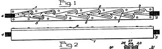


Links http://www.execpc.com/~teba (Tesla Engine Builders Association)
http://www.dnai.com/~zap/turbine.txt (Boundary Layer Breakthrough by Jeffrey Hayes)
http://www.frank.germano.com/tesla_turbine.htm (Frank Germano's work)
http://www.lindsaybks.com/bks5/tturb/index.html (W. Cairns: The Tesla Disc Turbine; Lindsay Publications)
http://www.tfcbooks.com/mall/turbomac.htm (21st Century Books ~ Tesla Turbomachinery)
http://groups.yahoo.com/group/TheTeslaTurbineList (Yahoo Discussion Group)
http://www.sredmond.com/disk_turbine.htm (S. Redmond's Tesla Turbine)
http://www.stanford.edu/~hydrobay/lookat/tt.html (Alan Swithenbank's Tesla Turbine)

Page 2 >>> ( N. Tesla: British Patent # 179,043 ~ "Production of High Vacua" // N. Tesla: British Patent # 186,082 ~ "Improvements in the Construction of Steam and Gas Turbines" // N. Tesla: British Patent # 186,083 ~ "Economic Transformation of the Energy of Steam by Turbines" // N. Tesla: British Patent # 186,084 ~ "Improved Process & Apparatus for Deriving Motive Power from Steam" // N. Tesla: British Patent # 186,799 ~ "Process & Apparatus for Balancing Rotating Machine Parts" )
Page 3 >> R. Hedin: "The Tesla Turbine" (Construction Plans); Live Steam (Nov. 1984) // Warren Rice: "Tesla Turbomachinery"; Proc. IV International Nikola Tesla Symposium (Sept. 23-25, 1991)