
Robert Vincent
http://www.wirelessnetdesignline.com/showArticle.jhtml?articleID=163103803
http://www.eetimes.com/;jsessionid=X2ETTT3FGOTKMQSNDLRCKHSCJUNN2JVN
Tweak
to Inductive Loading Shrinks Antenna
By
R. Colin
Johnson
PORTLAND, Ore. —
Independent tests appear to support an inventor's claim that
his skunk-works antenna design can shrink antenna size by up
to 70 percent while maintaining equivalent sensitivity and
increasing bandwidth.
The four-part
antenna cancels out the normal inductive loading in
traditional antenna designs, thereby linearizing the energy
radiation along its mast and enabling its diminutive size.
"When we announced
my smaller antenna design last year, I got lots of doubting
Thomases worldwide. Now, with the help of the Naval Undersea
Warfare Center and its antenna test range on Fishers Island,
N.Y., we have independent test results to back up our claims,"
said inventor Rob Vincent, a research engineer in the
University of Rhode Island's physics department.
Vincent calls his
invention a distributed-load monopole (DLM) antenna. The novel
design uses a helix plus a load coil to shrink the size of a
normal quarter-wave monopole. According to Vincent, his design
can shrink the size of every antenna in use today, from the
tiny gigahertz units inside cell phones to giant, kilohertz AM
antennas. For instance, a 3-inch-long gigahertz antenna could
be shrunk to an inch, and a 300-foot-tall AM band antenna
could be reduced to 80 feet high.
In the tests,
various DLM antennas from Vincent's portfolio were tested from
7 to 27 MHz. The results indicated that equivalent performance
was achieved with antennas 30 to 70 percent shorter than an
ideal quarter-wave antenna.
"Basically I am
utilizing the distributed capacitance around the antenna to
reduce the normally required inductive loading," Vincent said.
Vincent spent almost
30 years at Raytheon Co. and at KVH Industries (Middletown,
R.I.), before becoming a research engineer at the University
of Rhode Island (Kingston). He began experimenting with
antennas there as a skunk-works project.
Vincent chose the
Navy's Fishers Island Antenna Complex to test his design
because it is located in a low-lying, remote coastal area free
from radiation obstructions and man-made electromagnetic
interference. The complex offers a 1-mile range over seawater
between two sites for testing antennas ranging in frequency
from 2 to 30 megahertz. All gain measurements were done
relative to an ideal quarter-wave monopole antenna.
Vincent's antenna
designs were tested using the official regime the Navy uses to
certify its antennas. Vincent's Plano Spiral Top Hat antenna,
at 7 MHz, was shown to have equal sensitivity to a normal
quarter-wave antenna but at 50 percent the quarter-wave unit's
size. In addition, bandwidth of the Vincent design was nearly
twice as wide as that of the quarter-wave unit.
http://lists.contesting.com/pipermail/topband/2005-August/022116.html
Topband: May
2005 EET article about the DLM
Tom Rauch w8ji
at contesting.com
( Aug 20 07 )
The test antenna was
a 7MHz monopole, 50% of the normal quarter-wave size.
Now one thing from an illustration that begs more information
was the ground system. It shows 150' radials, which appear to
terminate at the sea water's edge. There is about a mile of
seawater between the test antenna and the calibrated receive
antenna.
The article
concludes; "Vincent's antenna designs were tested using the
official regime the Navy uses to certify antennas. Vincent's
Plano Spiral Top Hat antenna, at 7MHz, was shown to have equal
sensitivity to a normal quarter-wave antenna but at 50% the
quarter-wave unit's size. In addition, bandwidth of the
Vincent design was nearly twice as wide as that of the
quarter-wave unit."
The initial Vincent
claim read almost like CFA, CTHA, Fractal, and E-H antenna
claims. A very short antenna with makeshift construction was
claimed to produce better than full size performance. The
claims have evolved now to 50% shortening over a nearly
perfect ground produces equal FS.
The difference in FS
between a conventional 1/4 wl tall antenna and a 1/8th wl tall
antenna is within measurement error when the antenna is over a
very good ground system and when it uses a good loading
inductor regardless of where loading is placed. Brown, Lewis,
and Epstein knew that in the 1930's.
As a matter of fact
even with a loading coil Q as low as 250 (typically like air
core #16 wire) and using base loading there is less than 1dB
difference between a 1/8th wave and quarter wave antenna!
The apparent
endorsement of the DLM antenna by the U of RI does prove one
thing....we need to work on our educational system and
stop the backslide in science. The U of RI and Vincent are now
at the level of early 20th century antenna
technology.
73 Tom
http://www.ieee.org/portal/pages/products/whats-new/wncomm/wncomm0605.html
ENGINEER
DRASTICALLY SHRINKS ANTENNA, MAINTAINS SENSITIVITY AND
BANDWIDTH
A research engineer
at the University of Rhode Island has invented an antenna 70
percent smaller than conventional designs, but which has
comparable sensitivity and increased bandwidth. The antenna,
called a distributed-load monopole (DLM), uses a helix and a
load coil to shrink the size of a normal quarter-wave
monopole. In testing research engineer Rob Vincent's antenna
design, which cancels out the normal inductive loading, the
U.S. Navy found that the antenna achieved equivalent
performance with antennas 30 to 70 percent shorter than an
ideal quarter-wave design. Read more:
http://www.wirelessnetdesignline.com/showArticle.jhtml?articleID=163103803
http://www.eetimes.com/showArticle.jhtml?articleID=21600147
Antenna
design boosts efficiency per given size
R. Colin
Johnson
EE Times
(06/14/2004 9:00 AM EST)
Portland, Ore. - A
four-year skunk works effort at the University of Rhode Island
in Kingston has cut the size of an antenna by as much as
one-third for any frequency from the kHz to the GHz range.
Using conventional components, the four-part antenna design
cancels out normal inductive loading, thereby linearizing the
energy radiation along its mast and enabling the smaller size.
"The DLM
[distributed load monopole] antenna is based on a lot of
things that currently exist," said the researcher who invented
the smaller antenna, Robert Vincent of the university's
physics department, "but I've been able to put a combination
of them together to create a revolutionary way of building
antennas. It uses basically a helix plus a load coil."
The patent-pending
design could transform every antenna-from the GHz models for
cell phones to the giant, kHz AM antennas that stud the high
ground of metropolitan areas-Vincent said.
For cell phones, for
example, Vincent said he has a completely planar design that
is less than a third the size of today's cell phone antennas.
And those 300-foot tall antennas for the 900-kHz AM band that
dominate skylines would have to be only 80 feet high, with no
compromise in performance, using Vincent's design, he said.
"When looking at
these antennas, you pretty much have to forget everything you
ever knew about antennas and keep an open mind, because some
of the things I have done are very radical," said Vincent.
"With my technique, I reduce the inductive loading that is
normally required to resonate the antenna by as much as 75
percent . . . by utilizing the distributed capacitance around
the antenna."
NIMBY factor
Vincent, an amateur radio operator, embarked on his project
after he moved to a new neighborhood and his neighbors
objected to the 140-foot tall antenna he planned to erect for
a quarter-wave 1.8-MHz transmitter. So he surveyed the
literature, took the best of the best designs and combined
them into a 21-MHz test antenna that was 18 inches high, as
opposed to the 12- to 24-foot height of the antennas normally
used for that band. Building on that work, he eventually
devised a 46-foot-tall 1.8-MHz antenna his neighbors could
accept.
"I looked at all the
different approaches used to make antennas smaller, and there
seemed to be good and bad aspects" to each, Vincent said. "A
helix antenna is normally known to be a core radiator, because
the current profile drops off rapidly; they are just an
inductor, and inductance does not like to see changes in
current, so it's going to buck that. "But what I found was
that for any smaller antenna, if you place a load coil in the
middle you can normalize and make the current through the
helix unity; that is, you can maximize it and linearize it."
Vincent has verified
designs from 1.8 MHz to 200 MHz by measuring and
characterizing the behavior of his DLM antenna compared with a
normal quarter-wave antenna of the same frequency. He found
that many of the disadvantages of traditional antennas were
not problems for the much lighter inductive loading in a DLM.
"For instance, in a
normal quarter-wave antenna the current continually drops off
in a sinusoidal shape, but these antennas don't do that," said
Vincent. "The current at the top of the antenna is 80 percent
of the current at the base."
The reason more
current can be pumped into a DLM design than in a conventional
equivalent at the same size, Vincent theorized, is that the
DLM distributes energy more evenly along the antenna's length.
Using a DLM antenna one-third to one-ninth the size of
standard quarter-wave antenna, he measured nearly 80 percent
efficiency, when conventional wisdom would dictate that an
antenna the size of a DLM should be only 8 to 15 percent
efficient.
To check his theory,
Vincent analyzed and compared the current profiles, output
power and a score of other standard tests for measuring
antenna performance. All measurements were in reference to
comparative measurements made on a quarter-wave vertical
antenna for the same frequency, on the same ground system and
same power input.
"I was able to
increase the current profile of the antenna over a
quarter-wave by as much as two to 2.5 times," said Vincent.
"That is, the magnitude of the current in these antennas is
two to 2.5 times larger than for a normal quarter-wave
antenna.
"However, if you
measure the current profiles for both antennas and integrate
the area under the curves, you come out with the same volume,
indicating that the much smaller antenna is filling the
airwaves with the same amount of radio energy."
Vincent plans to
publish the results in a scientific journal soon, but with a
patent decision imminent, he couldn't hold off a preliminary
announcement that his theories regarding DLM antennas were
being supported by the experimental results. According to the
researcher, the DLM antenna profiles look just like the
theoretically ideal antenna profile-operating on a single
frequency with very high efficiency, while not producing any
interfering frequencies or wasting thermal energy.
"The phase and
amplitude of this antenna are a perfect mimic of the universal
resonance curve," said Vincent. "This makes the antenna
completely predictable well beyond its bandwidth. Another
unique feature is that these antennas have no harmonic
response whatsoever; as a matter of fact, to a certain extent
I used filter synthesis to design the antennas."
Nondescript
To the naked eye, the DLM antenna looks unremarkable, said
Vincent, who jokes that you could put a flag on his antennas
and they would look like flagpoles. But under the skin are
four main sections to the antenna (from bottom to top): an
inductive helix, a capacitive midsection, an inductive load
coil and a capacitive top section. The different lengths of
the mid- and top sections give them different resonant
frequencies, which, together with the exact values of
inductance and capacitance, define the antennas design
specifications for any desired frequency.
"The technology is
completely scalable: Take the component values and divide them
by two, and you get twice the frequency; take all the
component values and multiply them by two, and you are at half
the frequency," said Vincent. "There are two poles in the
antenna, and where I place the poles in relation to one
another-how much I bring the two resonant frequencies together
or spread them apart-enables me to emulate different antennas,
from a quarter-wave to a five-eighths wave."
Vincent said no
existing modeling software could adequately model his antenna
design. So he rolled his own simulation with Mathcad, making
use of some of Mathcad's filter design algorithms for the
inductive/capacitive-canceling effect.
"Eight years ago,
antenna design was 90 percent black magic and 10 percent
theory," said Vincent. "But now, with my design, they are 10
percent black magic and 90 percent theory."
The antennas are
also well-behaved, with wide bandwidth and easy to connect to
standard equipment, according to Vincent. For instance, they
can directly connect to standard 50-ohm antenna inputs without
any adapters.
"All I have to do is
tap the helix at its base, and you get a perfect 50-ohm match
with out any lossy networks [as are required for other
advanced antenna designs]," said Vincent.
For the future,
Vincent is moving up into the GHz bands for use with cell
phones and radio-frequency ID equipment. A problem in the past
has been that as components are downsized, they become too
small to utilize standard antenna materials. At 1 GHz, for
example, the helix is only eight-thousandths of an inch in
diameter and requires more than 100 turns of wire.
"So I came up with a
new way of developing a helix for high frequencies that is a
fully planar design; it's a two-dimensional helix," said
Vincent.
With the new helix
design, Vincent has built a prototype 7-GHz antenna that he
claims is indistinguishable from a quarter-wave antenna in all
but its size. "Because the new design is completely planar, we
could crank these out using thin-film technologies," Vincent
said.
Vincent received the
2004 Outstanding Intellectual Property Award from the
University of Rhode Island's Research Office, joint applicant
for the patent.
http://www.newswise.com/articles/view/511437/
Navy
Gives Small Antenna Big Results
Newswise — The news
last June that Rob Vincent, an employee in the Physics
Department at the University of Rhode Island, had shrunk the
antenna size without shrinking its effectiveness, produced a
large group of Doubting Thomases worldwide. Prove it, they
demanded.
Vincent and URI,
with the help of the Naval Undersea Warfare Center and its
antenna test range on Fishers Island, N. Y., have done just
that.
On March 31, 14
versions of Vincent’s Distributed Load Monopole (DLM) antennas
were put through a battery of validation tests. The results
exceeded Vincent’s and URI’s expectations. Smaller is better.
The Navy center
responds to a wide variety of military and commercial requests
for testing antennas at its Fishers Island over water range,
the only such range of its kind in the world. Water provides a
better path for transmission and reception than land. The site
is located on a low-lying, remote coastal area, free of local
interference.
The Fishers Island
range is a far-field ground wave antenna test range capable of
measuring the performance of antennas ranging in frequency
from 2 to 30 megahertz. Gain measurements are done relative to
an ideal quarter wave monopole antenna. The URI antennas were
tested using the same methods and instrumentation as those
used to test and certify Navy antenna systems.
Industry regards
such testing as dependable as science permits and often
includes the center’s data with products to assure customers
of its performance specifications.
Vincent’s Plano
Spiral Top Hat antenna at 7 megahertz is half the size of a
normal quarter-wave antenna operating at that frequency. The
URI antenna gain matched the performance of the ideal
quarter-wave antenna, and its bandwidth was nearly twice as
wide. This type of antenna has multiple uses, including
military, marine, amateur radio communications and AM
broadcasting.
In addition, the gain of Vincent’s capacity Top Hat DLM
antenna, which incorporates a helix, a load coil, a capacitive
top hat utilizing radial spokes at the top of the antenna and
a horizontal plane was nearly identical to the ideal quarter
wave antenna. Its bandwidth was greater than 5 percent of the
operating frequency and the antenna is more than 70 percent
shorter than an ideal quarter wave antenna.
Vincent’s standard
DLM antennas with a standard helix and load coil were also
tested at various frequencies. All exhibited gains nearly
equal to the ideal antenna with bandwidths of 3 to 10 percent.
The antennas were 33 to 40 percent shorter.
More than 200
businesses, companies, and government agencies have contacted
URI seeking information for automotive, marine, and military
applications, among others, since the antenna announcement
last year. A patent is pending on Vincent's technology. The
inventor has made the University of Rhode Island and its
Physics Department partners that will benefit from any revenue
his invention earns.
URI is close to
securing several license agreements. In addition, prototypes
have been developed for numerous applications.
View the test data
on URI’s antenna technology online. Visit the U.S. Navy’s
testing facility online for more information.
http://www.electronicproducts.com/ShowPage.asp?FileName=olrr01.aug2005.html
Antenna
Technology Shrinks Size, Not Effectiveness
by
Ralph Raiola
Tests at the Naval
Undersea Warfare Center's antenna test range have shown that a
new antenna technology, dubbed Distributed Load Monopole
(DLM), can shrink antenna sizes without loss of performance.
Developed last year by Rob Vincent, a technician in the
University of Rhode Island's physics department, the
technology could produce chip-mountable cell-phone antennas
that can be applied to WLAN applications, and promises to at
least double the range of walkie-talkies used by police, fire,
and other municipal personnel.
The DLM antenna
technology promises antennas up to 70% shorter than an ideal
quarter-wave antenna.
Several versions
have been developed, including the Plano Spiral Top Hat, a
7-MHz version that is half the size of normal quarter-wave
devices operating at that frequency. The device's gain matched
the performance of the ideal quarter-wave antenna, and its
bandwidth was nearly twice as wide.
The Top Hat DLM
antenna incorporates a helix, load coil, and capacitive top
hat using radial spokes at the top. More than 70% shorter than
an ideal quarter-wave antenna, its bandwidth is greater than
5% of the operating frequency.
Standard versions
featuring a standard helix and load coil were also tested at
various frequencies, all exhibiting gains nearly equal to the
ideal antenna with bandwidths of 3% to 10%. The antennas were
33% to 40% shorter.
The technology is
also being focused toward applications such as naval ships,
baby monitors, RFID, and portable antennas for military
equipment. The university is close to securing several license
agreements and prototypes have been developed for numerous
applications. For more information, call Rob Vincent of the
University of Rhode Island at 401-874-2063 or visit
http://www.uri.edu/news/vincent/report05
http://www.uri.edu/news/vincent/report05
Table of
Contents: Test Report --
http://www.uri.edu/news/vincent/report05/testreport.pdf
NUWC Report --
http://www.amta.org/StaticFiles/PDF/amta_2002/session%2013/a2002-13-02-072.pdf
Antenna Test Data (.zip) --
http://www.uri.edu/news/vincent/report05/data.zip
US Patent # 7,187,335
System
and Method for Providing a Distributed Loaded Monopole
Antenna
Robert J.
Vincent
( March 6, 2007
)
Abstract --
A distributed loaded antenna system including a monopole
antenna is disclosed. The antenna system includes a radiation
resistance unit coupled to a transmitter base, a current
enhancing unit for enhancing current through the radiation
resistance unit, and a conductive mid-section intermediate the
radiation resistance unit and the current enhancing unit. The
conductive mid-section has a length that provides that a
sufficient average current is provided over the length of the
antenna.
US Cl. 343/722
; 343/749; 343/841
Intl. Cl. 343/722 ; 343/749; 343/841
References Cited:
U.S.
Patent Documents: 3984839 // 4095229 // 4229743 //
4442436 // 4564843 // 4734703 // 5016021 // 5065164 // 5134419
// 5406296 // 5521607 // 5856808 // 5955996 // 6054958 //
6208306 //
6437756 // 6791504
Other References:
Harrison, Jr.,
"Monopole with Inductive Loading," IEEE Transactions on
Antennas and Propagation, Sandia Corporation, Albuquerque, NM,
Dec. 26, 1962, pp. 394-400. cited by other .
Fujimoto et al., "Small Antennas," Research Studies Press
Ltd., Letchworth, Hertfordshire, England & John Wiley
& Sons Inc., New York, 1987, pp. 59-75. cited by other .
"Now You're Talking!: All You Need to Get Your First Ham Radio
License," The American Radio Relay League, Inc., Second
Edition, Apr. 1996, Chapter 7, pp. 16-17. cited by other .
"The Offset Multiband Trapless Antenna (OMTA)," QST, vol. 79,
No. 10, American Radio Relay League, Inc., 1996, pp. 1-11.
cited by other .
"Mounting Tips for the Stealth II Series HF Mobile Antennas,"
Version 3.32, Aug. 2002, pp. 1-9. cited by other .
Nakano et al., "A Monofilar Spiral Antenna Excited Through a
Helical Wire," IEEE Transactions of Antennas and Propagation,
vol. 51, No. 3, Mar. 2003, pp. 661-664. cited by other .
"Helix Antenna,"
http://library.kmitnb.ac.th/projects/eng/EE/ee0003e.html, no
dated?. cited by other .
T. Simpson, "The Dick Loaded Monopole Antenna," IEEE
Transactions of Antennas and Propagation, vol. 52, No. 2, Feb.
2004, pp. 542-545. cited by other.
Description
BACKGROUND
The present
invention generally relates to antennas, and relates in
particular to antenna systems that include one or more
monopole antennas.
Monopole antennas
typically include a single pole that may include additional
elements with the pole. Non-monopole antennas generally
include antenna structures that form two or three dimensional
shapes such as diamonds, squares, circles etc.
As wireless
communication systems (such as wireless telephones and
wireless networks) become more ubiquitous, the need for
smaller and more efficient antennas such as monopole antennas
(both large and small) increases. Many monopole antennas
operate at very low efficiency yet provide satisfactory
results. In order to meet the demand for smaller and more
efficient antennas, the efficiency of such antennas must
improve.
There is a need,
therefore, for more efficient and cost effective
implementation of a monopole antenna, as well as other types
of antennas and antenna systems.
SUMMARY OF THE
INVENTION
In accordance with
an embodiment, the invention provides a distributed loaded
antenna system including a monopole antenna. The antenna
system includes a radiation resistance unit coupled to a
transmitter base, a current enhancing unit for enhancing
current through the radiation resistance unit, and a
conductive mid-section intermediate the radiation resistance
unit and the current enhancing unit. The conductive
mid-section has a length that provides that a sufficient
average current is provided over the length of the antenna.
BRIEF DESCRIPTION
OF THE DRAWINGS
The following
description may be further understood with reference to the
accompanying drawings in which:
FIG. 1 shows
a diagrammatic illustrative electrical schematic view of a
distributed loaded monopole antenna in accordance with an
embodiment of the invention;

FIG. 2 shows
a diagrammatic illustrative side view of a distributed loaded
monopole antenna in accordance with an embodiment of the
invention;

FIG. 3 shows
a diagrammatic illustrative graphical view of average current
distribution over length of an antenna in accordance with an
embodiment of the invention;

FIG. 4 shows
a diagrammatic illustrative top view of a top unit for use in
accordance with an embodiment of the invention;

FIG. 5 shows
a diagrammatic illustrative side view of an antenna in
accordance with an embodiment of the invention employing a top
unit as shown in FIG. 5;

FIG. 6 shows
a diagrammatic illustrative top view of another top unit for
use in an antenna in accordance with a further embodiment of
the invention;

FIG. 7 shows
a diagrammatic illustrative side view of a radiation
resistance unit for use in an antenna in accordance with an
embodiment of the invention;

FIG. 8 shows
a diagrammatic illustrative side view of an adjustment unit
for use in an antenna in accordance with an embodiment of the
invention;

FIG. 9 shows
a diagrammatic illustrative side view of the slotted tube
shown in FIG. 8;
FIGS. 10A and 10B
show diagrammatic illustrative side views of the tapered
sleeve shown in FIG. 8;
FIG. 11 shows
a diagrammatic illustrative side view of another adjustment
unit for use in an antenna in accordance with an embodiment of
the invention;

FIG. 12 shows
a diagrammatic illustrative side view of the slotted tube
shown in FIG. 11;
FIG. 13 shows
a diagrammatic illustrative side view of the sleeve shown in
FIG. 11;
FIG. 14 shows
a diagrammatic illustrative isometric view of a radiation
resistance unit for use in an antenna in accordance with an
embodiment of the invention;

FIGS. 15A, 15B
and 15C shows diagrammatic illustrative isometric, front
and side views of a current enhancing unit for an antenna in
accordance with an embodiment of the invention;

FIGS. 16 and 17
show diagrammatic illustrative side views of antennas in
accordance with further embodiments of the invention employing
the radiation resistance unit shown in FIG. 14;

FIG. 18 shows
a diagrammatic illustrative isometric view of a plurality of
monopole antennas in accordance with the invention being used
together in a multi-frequency system;
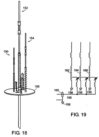
FIG. 19 shows
a diagrammatic illustrative electrical schematic of a portion
of the system shown in FIG. 18;
FIG. 20 shows
a diagrammatic illustrative side view of an antenna in
accordance with an embodiment of the invention that forms a
loop antenna system;

FIG. 21 shows
a diagrammatic illustrative side view of an antenna in
accordance with an embodiment of the invention that forms a
dipole antenna system;

FIG. 22 shows
a diagrammatic illustrative electrical schematic of an antenna
in accordance with an embodiment of the invention;

FIG. 23 shows
a diagrammatic illustrative side view of an antenna in
accordance with an embodiment of the invention; and

FIGS. 24, 25 and
26 show diagrammatic illustrative side views of antennas
in accordance with further embodiments of the invention;

The drawings are
shown for illustrative purposes only.
DETAILED
DESCRIPTION OF THE ILLUSTRATED EMBODIMENTS
A distributed loaded
monopole antenna in accordance with an embodiment of the
invention includes a radiation resistance unit for providing
significant radiation resistance, and a current enhancing unit
for enhancing the current through the radiation enhancing
unit. In certain embodiments, the radiation resistance unit
may include a coil in the shape of a helix, and the current
enhancing unit may include load coil and/or a top unit formed
as a coil or hub and spoke arrangement. The radiation
resistance unit is positioned between the current enhancing
unit and a base (e.g., ground), and may, for example, be
separated from the current enhancing unit by a distance of
2.5316.times.10.sup.-2.lamda. of the operating frequency of
the antenna to provide a desired current distribution over the
length of the antenna.
As shown in FIG. 1,
an electrical schematic diagram of an antenna 10 in accordance
with an embodiment of the invention includes a radiation
resistance unit 12 and a current enhancing unit 14. The
radiation resistance unit 12 (such as, for example, a helix)
may be formed in a variety of shapes, including but not
limited to round, rectangular, flat and triangular. The
radiation resistance unit 12 may be wound with wire, copper
braid or copper strap or other conductive material around the
form and is such that it's length is very much longer than
it's width or diameter.
The current
enhancing unit 14 may also be formed of a variety of
conductive materials and may be formed in a variety of shapes.
The unit 14 is positioned above the unit 12 and is separated a
distance above the unit 12 and supported by a mid-section 16
(e.g., aluminum tubing). The current enhancing unit 14 when
placed a distance above the radiation resistance unit 12
performs several important functions. These functions include
raising the radiation resistance of the helix and the overall
antenna.
The above antenna
provides continuous electrical continuity from the base of the
helix to the top of the antenna. The base of the antenna is
grounded as shown at 18, and the signal to be transmitted may
be provided at any point along the radiation resistance unit
12 (e.g., near but not at the bottom of the unit 12). The
signal may also be optionally passed through a capacitor 22 in
certain embodiments to tune out excessive inductive reactance
as discussed further below.
FIG. 2 shows an
implementation of the above antenna system in which the
radiation resistance unit is formed as a helix 30, and the
current enhancing unit is formed as a load coil 32. The helix
30 is formed as a conductive coil that is wrapped around a
non-conductive cylinder wherein the coil windings are mutually
spaced from one another by a distance of approximately the
thickness of the coil. The bottom of the helix coil is
connected to ground as shown at 34, and the top of the helix
coil is connected to a conductive mid-section 36 between the
helix 30 and the load coil 32. The load coil is formed as a
tightly wrapped spiral, the base of which is connected to the
mid-section 36 and the top of which is connected to a
top-section 38. The mid-section 36 may separate the helix 30
and load coil 32 by a distance as indicated at A. The signal
to be transmitted is coupled to the antenna by a coaxial cable
40 whose signal conductor is coupled to one of the lower helix
coil windings near the base as shown at 42, and whose outer
ground conductor is coupled to ground as shown.
The choice of the
distance A of the load coil above the helix impacts the
average current distribution along the length of the antenna.
As shown in FIG. 3, the average current distribution over the
length of the antenna varies as a function of the mid-section
distance for a 7 MHz distributed loaded monopole antenna. The
mid-section distance is shown along the horizontal axis in
inches, and the percent of average current over the antenna
length is shown along the vertical axis. The relationship
between the mid-section distance and the percent of average
current is shown at 50 for this antenna. The current
distribution for this antenna peaks at about 42 inches as
shown at 52. The conductive mid-section has a length that
provides that a sufficient average current is provided over
the length of the antenna and provides for increasing
radiation resistance to that of 2 to nearly 3 times greater
than a 1/4.lamda. antenna (i.e., from for example, 36.5 Ohms
to about 72 100 Ohms or more).
The inductance of
the load coil should be larger than the inductance of the
helix. For example, the ratio of load coil inductance to helix
inductance may be in the range of about 1.1 to about 2.0, and
may preferably by about 1.4 to about 1.7. In addition to
providing an improvement in radiation efficiency of a helix
and the antenna as a whole, placing the load coil above the
helix for any given location improves the bandwidth of the
antenna as well as improving the radiation current profile.
The helix and load coil combination are responsible for
decreasing the size of the antenna while improving the
efficiency and bandwidth of the overall antenna.
In further
embodiments, a top unit 60 may also be provided that includes
eight conductive spokes 62 that extend from a conductive hub
64 as shown in FIG. 4. The spokes 62 may be held within small
holes by set screws through which they are electrically
connected to the conductive top-section 38 of the antenna. As
shown in FIG. 5, the top unit 60 may be placed atop an antenna
such as the antenna shown in FIG. 2. This may further reduce
the inductive loading of the helix and load coil to allow even
wider bandwidth and greater efficiency. The top unit is
included as part of the current enhancing unit. In further
embodiments, the top unit may be used in place of the load
coil as the current enhancing unit.
A current profile
for a 12 foot antenna employing a helix and load coil
(starting at 7.5 feet) was found to show 100 percent current
up to an elevation of about 7 feet, while a similar 9.5 foot
antenna using an additional top unit was found to show 100
percent current up to an elevation of about 8 feet. The
structure provides electrical continuity from the base of the
helix to the top of the top section. The top unit may, in
further embodiments, include a planar spiral winding that
extends radially from, and in a transverse direction with
respect to, the antenna as discussed below in connection with
FIG. 6.
There is an
electrical connection from the bottom of the helix up through
the helix and through the midsection and continues through the
load coil to the top section. The helix at the bottom has
provisions for tapping the turns of the helix. This allows
connection from a source of radio frequency energy and proper
matching by selecting the appropriate tap to facilitate
maximum power transfer from the radio frequency source to the
antenna. The placement of the load coil provides linear phase
and amplitude responses through the bandwidth of the antenna
and even beyond the normally usable bandwidth of the antenna.
It has also been found that such an antenna has no harmonic
response, and that its response is similar to that of a low Q
band pass filter.
The antenna shown in
FIG. 2 may be mounted by clamping the base of the helix to a
mounting pole that has been driven into the ground. Clamps may
be used to affix the antenna sufficiently to the ground
mounting post. In this embodiment the antenna is shown
grounded to earth through a grounding rod, ground wire and
connected to the base of the antenna and electrically
connected using a ground clamp. Radial wires extending above
ground or buried in the ground are electrically connected to
the antenna using the ground wire and the ground rod and
extend out from the antenna base for a uniform distance but
not limited to any specific length. This grounding system
comprised of a ground rod and radial wires may also take on
many forms such as a large piece of copper or other conductor
screen of any given geometric shape. This grounding system may
also take on the form of a metal plane such as a ship,
automobile, or a metal roof of a building among others. The
antenna may also be elevated above ground on a conductive post
with radial wires extended as guy wires to support and keep
antenna in the upward erect position. These guy wires serve as
an elevated ground poise or radial system.
The feed for the
antenna from a radio frequency source is tapped a few turns
from the base of the helix driven by a radio frequency source
and connected by a coax cable. The shield of the coax cable is
connected to the base of the helix which is grounded to the
ground rod. The radio frequency source is used to excite the
antenna and cause a radio frequency current to flow which
causes the distributed loaded monopole antenna to radiate.
As indicated above,
the design of the helix and interaction of the load coil are
such that the antenna exhibits a large and uniform current
distribution for various lengths along the antenna. The length
and uniformity of this current profile is dependent upon the
ratios of inductance between the load coil and the helix as
well as location of placement of the load coil above the
helix. In addition, the placement of the load coil allows
larger than normal bandwidth measured as deviation from
resonant frequency either side of resonance in which
sufficient match between the source of radio frequency energy
and the antenna can be maintained to allow the antenna to
radiate with reasonable efficiency. In addition, the
interaction of the helix and load coil allows reduction of the
physical height of the overall antenna without reducing
electrical height and provides for an increase in radiation
resistance. This increase in radiation resistance reduces the
effect of losses associated with short antennas. These losses
include resistance in the wires of the helix and load coil and
Ohmic resistance of the antenna conductors and that of the
ground system. All or any of these has a pronounced effect on
antenna radiating efficiency, reduction of antenna bandwidth
and overall performance in shortened antennas. The design of
the distributed loaded monopole antenna with a helix and load
coil above the helix overcomes those losses and provides a
high level of radiating efficiency with excellent bandwidth in
a small compact easily implemented antenna.
The physical
structure of an antenna and the interaction of the components
as described above allow for maximum use of distributed
capacity along the antenna to ground to reduce inductive
loading required to resonate the antenna to a given desired
radio frequency. This increases efficiency, raises radiation
resistance and improves bandwidth. This also allows the
antenna to have amplitude and phase response through resonance
that resembles a universal resonance response curve with
linear deviations in amplitude and phase for bandwidths far
exceeding the normal half power bandwidth of the antenna.
The antenna of FIG.
5 may be formed as follows. A helix is formed by wrapping a
conductive material around a tubular non-conductive form, such
as fiberglass, PVC or other suitable tubular insulator. In
further embodiments, any form may be used such as those that
are also square, rectangle or triangular in cross section.
Attached to the top of the helix is a top fitting that is
formed of a conductive material such as aluminum or other
suitable conductive material. In this embodiment these are
machined but can also be cast from aluminum or other suitable
conductive material. Slots are cut in the top fitting to allow
clamping on to a aluminum tubing of such diameter that they
form a tight mechanical fit when such tubing is inserted. This
fitting is inserted into the helix tube and in this embodiment
is epoxy bonded together with the helix and fitting. It may
also be fastened with machine screws provided the helix form
is drilled and the fitting has been drilled and threaded.
Likewise a bottom helix fitting is machined or cast of
aluminum or other conductive material is attached to bottom of
helix. This fitting is solid aluminum and has mounting rod. A
helix insertion rod has been epoxy bonded to the helix form.
The main section forms a conductive mounting point for this
lug and helix winding. A helix winding is attached at the base
fitting with a solder lug or other conductive connecting
material and fastened electrically and mechanically to the
helix end fitting with a machine screw. The helix is wound
with copper strap but not limited to this material but can be
wire or copper braid wound in a circular manner over the
entire length of the helix form and attached to the helix top
fitting using, for example, a solder lug. Other conductive
connecting devices may be used to allow electrical and
mechanical assembly with a machine screw into the drilled and
threaded hole. The helix at the bottom has machine nuts or
similar connecting devices soldered to the winding for
attachment of the center conductor of a coax cable.
Inserted into the
top of the helix fitting is a tubing that is held rigidly in
the helix top fitting using a clamp. The load coil includes a
section of fiberglass tubing that is attached with end
fittings that are epoxy bonded to form a strong mechanical
connection with both the mid-section and the top-section. The
load coil end fittings are machined or cast aluminum. Each of
these fittings is slotted and formed, or machined to accept
mid-section tubing or top section tubing, which are
electrically connected to the load coil itself. The load coil
form is wound with heavy copper wire but may be any other
heavy conductive material that is closely wound as shown to
form a solenoid. Each end is connected to the load coil end
fitting with a lug on each end, and attached electrically and
mechanically with machine screws that are screwed into holes
that have been drilled and threaded into load coil end
fittings. Two pieces of tubing form the top section. The lower
tube section at the top has been slotted to allow the upper
tubing section to be inserted in a telescoping manner into
tubing section to permit adjustment of the overall top section
length to tune the antenna. Once adjusted, the tubing sections
are secured with a clamp to form a rigid mechanical and
electrical connection. There is now an electrical connection
from the bottom of the helix winding from the helix bottom
fitting to the top of the top section.
The completed
distributed loaded monopole antenna consisting of the helix
30, the mid-section 36, the load coil 32 and the top section
38 is shown in FIG. 5 mounted on a ground mounting pipe of
conductive material using clamps. The coax cable with a center
conductor is shown connected to one of the tap points at
bottom of helix. The coax shield is electrically connected to
the helix base fitting with an electrical clamp. The ground
wire 34 is connected to the electrical clamp (and therefore to
the ground base of helix) and to a ground rod 44 in the
ground. Attached to the ground rod 44 and ground wire are
radials 46 that are either buried or lying on the ground. The
radials 46 may be of sufficient length and number to provide
an adequate counterpoise for operation of the distributed
loaded monopole antenna.
The hub 64 of the
hub and spoke top unit 60 shown in FIG. 4 may be fabricated
from an aluminum disk of sufficient size to accommodate the
eight radial aluminum conductors or spokes 62. To use the top
unit 60, the normal antenna design inductance for the helix
and load coil must be decreased by 1/2 in order to resonate
the antenna to the same frequency. The overall antenna height
decreases by about 25%. The bandwidth of the antenna increases
by a factor of 2.5 times or more over that of a normal design.
In addition the antenna increases in efficiency by more than
10% as compared to a normal distributed loaded monopole
design.
The top unit hub 64
is drilled with eight holes spaced every 45 degrees around the
circumference of sufficient diameter and depth to accept the
conductive radial spokes 62. Eight holes are also drilled in
the top of the hub along the outer rim and are aligned over
the eight holes previously drilled and are threaded to accept
set screws that secure the radial conductive spokes 62. All
the spokes 62 are of the same length and of sufficient
diameter and strength to be self-supporting extending
horizontally out from the hub as shown in FIG. 5. The complete
top unit with hub and spokes is slipped over the top section
of the distributed loaded monopole antenna and horizontally
extends in all directions as shown in FIG. 5. The antenna is
tuned by decreasing or extending the height of the top unit
above the load coil of the antenna. The top unit is provided
to maximize and make uniform the current profile of the
antenna from the base to as high along the antenna length as
possible while providing improved bandwidth and efficiency.
In other
embodiments, the top unit 70 may include a non-conductive hub
72 with eight non-conductive rods 74 extending from the
center-insulated hub 72 as shown in FIG. 6. These rods may be
formed of an insulating material that may be used for radio
frequencies. The top section extends through the hub 72 and is
then connected to a large conductor or wire 76 at a first end
78 of the wire. The other end 80 of the wire is not
electrically connected to any conductive material. This wire
76 is wound in a spiral form from the center in an increasing
diameter. This forms a large spiral conductor at the very top
of the antenna as well as provides capacitive loading. The
function of this configuration is to maximize and make uniform
the current profile from the base of the antenna extending all
the way to the top of the antenna.
When using the top
unit 70 with a load coil and helix of the antenna shown in
FIG. 2, the inductance for the helix and the load coil must be
reduced by about 1/2(50%). This will allow the antenna to
resonate at the same frequency.
For the combined
capacitive top unit and load coil of FIG. 5, the load coil and
helix inductance is also reduced by about 50%. The overall
antenna height decreases by about 25% for the capacitive top
unit antenna and for the combined load inductor and top unit
combination the antenna height remains the same or in some
cases may be slightly larger.
In further
embodiments, the bandwidth of the antenna may be enhanced by
including an additional coiled wire 82 in a top unit as also
shown in FIG. 6. The additional wire 82 includes first and
second ends 84 and 86 that are each not electrically connected
to any conductive material. It has been found that interlacing
a false winding into a current enhancing unit (such as the top
unit winding shown in FIG. 6) or a radiation resistance unit
(such as a helix as shown in FIG. 7) enhances the bandwidth of
the top unit as well as improves the current profile along the
antenna. The interlaced false winding has little effect on the
resonant frequency of the antenna system.
Similarly, a false
winding may be provided in a helix of an antenna in accordance
with an embodiment of the invention as shown in FIG. 7 to
enhance the bandwidth of the helix. In this embodiment, a
radiation resistance unit 90 includes a helix winding 92 that
is wound around a non-conductive tube and electrically
connected at each end to electrical couplings. An additional
winding 94 is interlaced within the helix winding but is not
connected electrically to any point within the helix or at the
ends of the winding 94. The winding 94 is merely suspended
within the helix winding 92 as shown in FIG. 7. This false
winding 94 has been found to enhance the bandwidth of an
antenna by as much as 100% (i.e., doubling it). The effect of
this false winding is to reduce the capacitance between helix
and load coil windings, which has been found to be a bandwidth
limiting mechanism in helix coils and load coils.
In further
embodiments, the resonance of an antenna of the invention that
includes a helix may be changed by adding to or removing from
the helix, a turn of winding turns of the helix to change coil
inductance. This may be accomplished by employing a coil
adjustment unit such as units 100 or 110 as shown in FIGS. 8
and 11 respectively. The coil adjustment unit 100 shown in
FIG. 8 includes an electrically conductive slotted tubing 102
(shown in FIG. 9) that is received within the tubing of the
helix, i.e., the tubing around which the helix coil (not
shown) is wrapped. An electrically conductive tapered sleeve
104 is then inserted within the tubing 102. The slotted tubing
102 may be made from aluminum or any other non-ferrous
conductive material. The slot 106 in the tubing 102 is cut
lengthwise as shown and may be any convenient width but not
greater than 1/6 of the tubing circumference. The top of this
tubing should have slots cut to allow a clamp to securely
fasten telescoping tubing to be inserted into tubing (102).
The total length of this tubing should be such that the
portion slotted will fit into the helix tubing and locked into
the helix top fitting clamp assembly using a clamp as
discussed above.
A portion of the
tubing 102 should also protrude from the helix for the
additional non-ferrous sleeve 104 to easily slide inside and
be secured using a clamp. This sleeve 104 is cut lengthwise as
shown to create a long angled section 108. This sleeve 104
when fitted into the slotted tubing 102 provides variations in
opening or closing the slot responsive to turning the sleeve
104 with respect to the tubing 102. This permits eddy currents
to circulate within this tubing combination where the slot has
been closed by the twisting action of tubing. The effect of
the slotted tubing when the slot is open is minimal on the
helix inductance. When the slot is filled or closed by the
rotation of the sleeve 104, eddy currents will be allowed to
flow and electrically short out turns of the helix therefore
allowing variations of the helix inductance. This same
technique may be used for solenoid coils of any length thereby
allowing adjustment of the inductance. The number of windings
and/or the length of a load coil may also be adjusted using
such an adjustment unit.
Similarly, the coil
adjustment unit 110 shown in FIG. 11 includes an electrically
conductive slotted tubing 112 having a slot 114, and a
conductive sleeve 116. In this case the sleeve 116 does not
include a tapered edge, and the unit 110 is adjusted by
varying the distance to which the sleeve 116 is inserted
within the slotted tubing 112. In both cases, once the
adjustment has been made to satisfaction the adjusting tubing
is clamped securely.
In addition to these
embodiments, the distributed loaded monopole antenna may take
on other forms. These include reducing the height of the
antenna and inductance of the helix and load coil, and
affixing at the top of the top section a horizontal series of
electrical conductors extending out from the center in the
form of spokes for a given distance. These conductors may be
any arbitrary number and are arranged as spokes from a hub as
discussed above. In accordance with further embodiments, a
plain sheet of metal or conductive screen may also be used.
Other such embodiments may also be employed where they provide
for a large capacitance from the top of the antenna to ground.
This capacitance provides for further uniform distribution of
current for an even greater distance along the antenna height
or length. This further allows for wider bandwidth operation
and higher efficiency.
Further embodiments
provide that a helix may be constructed as a lattice network
of wider width than thickness as discussed below with
reference to FIGS. 14 17. This embodiment may take on the form
of a latticework constructed of insulating material that is
adequately braced along its height or length. The ends of the
latticework consist of fabricated aluminum pieces so shaped to
support the lattice structure at each end. Winding suitable
conductors as described above around the structure from the
base to the top forms a helix. The winding is such that the
number of turns per unit length is higher at the bottom than
at the top. The top of this helix winding is electrically
terminated to the conductive lattice termination. These
aluminum pieces or suitable conductors provide for affixing
additional conductors in the form of tubing, rod or pipe. In
this manner, the antenna may be extended in length or height
and provide for electrical connection of the helix winding.
This extends the electrical connection from ground up through
the helix to the top of the antenna through the load coil. The
aluminum or any conductive material at the top of the helix
structure allows for terminating the helix winding and
provides electrical connection to the above mentioned upper
structures of the antenna. These upper structures include a
mid-section as discussed above. A load coil of any of a
variety of geometric shapes may also be employed as further
discussed below. To allow connection and proper matching
between a radio frequency source and the antenna this
above-described helix provision is allowed for tapping the
helix conductor anywhere along its length from the bottom of
the antenna. The rectangular helix geometry and various load
coil geometry allow further reduction of required loading in
the form of inductance and enhance further the distributed
loading affect of capacity along the length of the antenna to
ground. This allows even further improved bandwidth and
radiation efficiency. This embodiment may also be used with
variations in load coil inductance and helix length and helix
inductance, together with a series capacitor match between
helix tap and the source of radio frequency energy. These
variations allow equivalent performance to a conventional
antenna as much as 9 times larger in size.
Current profiles
have been developed for various such embodiments of 1/2 wave
and 5/8 wave distributed loaded monopole antennas. The
manipulation of helix length and inductance as well as the
ratio of load coil to helix inductance may achieve a wide
variety of suitable antennas.
In addition to the
above embodiments, providing a remotely controlled top section
length may yield a distributed loaded monopole antenna that is
continuously tunable over a large frequency range. This may be
achieved utilizing a motor driven worm gear or any other
method of varying remotely the adjustment of the top section
length. Similarly the antenna may be tuned by varying the
helix inductance. This may be accomplished by varying the
electrical length of the helix but without changing the
mid-section length between the helix top and load coil.
In particular, an
antenna in accordance with further embodiments may include a
radiation resistance unit 120 having a non-electrically
conductive structure 122 around which is wrapped a conductive
material 124 in the form of a helix as shown in FIG. 14. The
structure 122 may be provided by four elongated edge elements
126 that are each connected to internal non-conductive bridges
128. The end portions 130, 132 are conductive and are
electrically connected to each of the ends 134, 136
respectively of the conductive material 124. Each of the
bridge portions 128 includes a central hole through which a
non-conductive tube may pass, and the conductive end portions
130, 132 also include such an opening as well as a clamp for
attaching the unit 120 to the conductive mid-section of an
antenna at the upper end of the unit 120 and to ground at the
lower end of the unit 120. The mid-section may further include
a reinforcing fiberglass rod.
The conductive
material 124 may be any suitable conductor such as copper
strips (that are thin in depth and wide in width) or copper
braid, wire or similar material. The bottom of the winding is
fastened and electrically connected to the aluminum or similar
conductive bottom plate. The end of the helix winding material
is fastened using suitable wire connecting lug or conductive
strip and soldered to provide a low loss electrical
connection. The lug or connecting strip is fastened with a
machine screw to a hole drilled into bottom plate which has
been threaded to accept a machine screw. This provides a
secured electrical connection. A similar fastener may be used
to connect the top end of the helix winding to the helix top
plate.
The antenna shown in
FIG. 16 may provide near 1/2 wave vertical antenna
performance. The mid-section may be lengthened or shortened as
discussed above to tune the resonance of the antenna.
Similarly, the antenna shown in FIG. 17 may provide improved
performance with additional bandwidth, The current enhancing
unit 140 of FIG. 17 may be formed using a conductive
planosprial coil 142 that is sandwiched between two
non-conductive discs 144 and mounted to a non-conductive tube
section 146 as shown in FIGS. 15A, 15B and 15C. The ends of
the coil 142 are passed through two openings 148 and 150 in
the inner disc and connected to the conductive mid-section and
top-section of the antenna. Adjustment of the length of the
top-section (as discussed above) may further be used to tune
the antenna to resonance. In either antenna, various ratios of
load coil to helix inductance may permit various performance
levels of the antenna to be optimized.
When a flat antenna
is designed for resonance much lower than normal, it will give
5/8 wave performance. The embodiment shown in FIG. 14 uses the
flat helix but this helix is a little longer by about 10%.
This allows a slightly higher inductance in the helix.
The embodiment shown
may be ground mounted as discussed above using a base mounting
rod. Attached to this base mounting rod may be an enclosure
housing a capacitor (e.g., 22 as shown in FIG. 1) and a
standard coax receptacle. The center conductor of this coax
receptacle is connected to one side of the series capacitor
using a short wire. The coax shield is connected electrically
through the enclosure box mounting plate and clamps to the
base of the antenna, mounting post and the radial/ground
system. The other side of the capacitor is connected to a feed
through also using a short wire from the capacitor, and this
short wire exits outside the box for connection of an
additional wire that is used to tap the helix base a few turns
from the bottom. Also connected to the base mounting rod is a
grounding wire that is connected to a ground rod. The base
mounting rod is a conductive material and is driven into the
ground. This rod is securely connected to the helix base plate
which is also conductive. This allows grounding the base of
the helix and the beginning of helix winding to the ground
using the ground wire and the ground rod.
Radials are run on
top of or in the ground by burying them under the surface. The
radials are extended out from the base in a circular manner
like the spokes extending from the hub of a wheel (similar to
the hub and spoke structure of the top unit shown in FIG. 4).
The radials are electrically connected to the base of the
antenna through the ground rod and wire. This allows including
the radials as part of the antenna ground system and serves as
an electrical counterpoise.
The antenna shown in
FIG. 17 may be made for 1/4 wave performance using suitable
values of helix and load coil, together with proper dimensions
of the top and bottom sections. This provides extended
bandwidth performance and improved efficiency. The antenna may
utilize either load coil (32 or 140), and the helix length is
reduced slightly to permit the antenna to resonate just below
the lower frequency of operation. In this antenna, there is no
need for the capacitor coupling (22 of FIG. 1) to tune out the
added inductance.
In further
embodiments, antennas of the invention may be combined to form
other antenna systems such as dipoles where two antennas are
placed back to back and their helixes electrically connected
at a mutual base. The method of connecting the radio frequency
source is to tap the helix from the middle and extend to each
side till a suitable match between source and load can be
achieved. A balanced matching transformer or BALUN can be used
to drive the feed point. In addition, the antenna may be
arranged in vertical positions along the ground and formed
into arrays of antenna elements providing directional
transmission. Distributed loaded monopole elements combined
into dipoles may be further combined to form horizontally or
vertically polarized arrays such as yagis or phase driven
arrays of any number of elements. Such elements may also be
combined into loops providing directional characteristic with
improved sensitivity compared to other loop forms.
For example, as
shown in FIG. 18 multiple antennas 150, 152, 154 of different
resonant frequencies resulting in different physical sizes may
be used together to provide a multi-frequency system on a
common, electrically conductive, mounting stage 156. An
equivalent electrical schematic diagram of three such antennas
sharing the common mounting stage is shown in FIG. 19. This
mounting stage (which may be elevated from ground) may be any
conductive surface such as a vehicle or a ship or a large
metal sheet such as a roof of a building. When mounting in an
elevated manner using a long pole such that the antennas and
the mounting surface are some height above ground, the ground
radials may be used to as a counterpoise as well to stabilize
the structure. It is not required that any counterpoise or
radial system be resonant
As shown in FIG. 19,
a single coaxial feed line 160 is used from the source of
radio frequency excitation. All three antennas are connected
to the coaxial feed in a parallel manner. The proper selection
of antenna is provided by the series tuned circuits connecting
to the proper tap point on each helix 162, 164, 166. At the
frequency of operation and resonance of the particular
antennas selected the series resonant coupling circuits will
be of sufficiently low impedance to couple the coaxial feed to
the proper antenna. The series coupling elements not in use
will be sufficiently de-coupled by virtue of their relatively
high impedance. This configuration by virtue of this operation
will provide efficient operation for each antenna to be
automatically selected.
Antennas used in
accordance with further embodiments of the invention may
provide a pair of distributed loaded monopole antennas as a
half wave loop or two pairs may be used form a full wave loop.
FIG. 20 shows two such antennas used as a half wave loop. A
first antenna 170 includes a helix 172 and a load coil 174,
and a second antenna 180 includes a helix 182 and a load coil
184. A variable capacitor may be coupled between the upper
ends 176 and 186 of the antennas 170 and 180. The taps near
the lower ends 178 and 188 of the antennas 170 and 180 may be
coupled to a first balanced transformer winding while a second
transformer winding is coupled to a coaxial connector port
190. In other embodiments, the end 192 of the one antenna 170
may be coupled to the first conductor of the coaxial connector
190, while the second conductor of the coaxial connector is
coupled to a tap near the lower end 188 of the antenna 180.
During operation,
the loop may be resonant at a higher operating frequency, and
the loop may be tuned to resonance using the variable
capacitor between the ends 176 and 186 of the antennas 170 and
180. If the loop is used for transmitting, the variable
capacitor must be of sufficiently high voltage rating so as
not to be broken down by the very large high radio frequency
voltages generated across this capacitor. To implement the
configuration or embodiment as shown, the midsections of each
monopole element are bent into a 90-degree right angle. The
bottoms of the helixes are joined using a conductive coupling.
The entire loop is mounted on an insulated pole and may be
rotated. The loop is feed with an unbalanced coax feed line
and the transformer may be used to balance the loop. A virtual
ground exists where the helix bases are joined. Because of
this virtual ground the loop may be fed unbalanced while the
coax shield is grounded at the helix joining point. To match
the loop to the source in either case, it is only necessary to
select the proper tap of the helix.
Antennas in
accordance with various embodiments of the invention may also
be coupled as a distributed loaded dipole as shown at 200 in
FIG. 21. The dipole antenna 200 includes two load coils 202
and 204 that are each mutually spaced from an intermediate
(double length) helix 206, which is formed by joining two
helixes together at their ends. Taps taken from either side
near the center of the helix are coupled to either side of a
first winding of a balanced transformer 208. The second
winding of the transformer is coupled to each of the two
conductors of a coaxial connector 210 as shown. The
transformer may be mounted in an enclosure. Selection of the
proper tap points from the middle to each side of the helix
winding should provide a sufficient impedance match to the
radio frequency source. The transformer enclosure may be
mounted a short distance from the dipole antenna and connected
with short wires as indicated.
Antennas in
accordance with further embodiments of the invention may
include a current enhancing unit 210 and a radiation
resistance unit 212 wherein the radiation resistance unit 212
is not formed as a helix or even a spiral that rotates about
the longitudinal axis of the antenna, but rather as a
planospiral that rotates about an axis that is orthogonal to
the longitudinal axis of the antenna as shown in FIG. 22. The
coil of the unit 212, therefore, is formed as a coil that
extends back and forth along a length of the unit 212. The
antenna may be driven by a transmission signal (as indicated
at 214) by tapping onto a portion of the coil of the unit 212
near but not at the ground end of the coil in unit 212.
For example, as
shown in FIG. 23, the current enhancing unit may comprise a
load coil 32 as discussed above with reference to FIG. 2. The
radiation resistance unit 220, however, includes a coil 222
that extends from one end 224 (at ground) to a second end 226
by wrapping up and down the length of the unit 220 as shown in
FIG. 23. The antenna includes four main parts similar to the
antenna shown in FIG. 2. The current enhancing unit shown in
FIG. 23 includes a central support element 228, the coil of
wire 222, and coil wire stringers 230 and 232 at the top and
bottom of the center support element.
Inserted into the
center support element (which consists of a 1-inch square
fiberglass pole) is an aluminum mounting rod 234 and a
mid-section attachment rod 236. The coil wires 222 are strung
vertically along the support element 228 to form an elongated
spiral loop. This loop is fastened to the mid-section 236
using solder lugs and bolted to the mid-section attachment
rod. The mid-section is attached by slipping this mid section
tubing over the attachment rod and clamping them together
using clamps. The lower part of the loop is attached to the
aluminum mounting post 234 using wire lugs that arc screwed
into the mounting post through the fiberglass main support
holding the wire coil 222. The ground wire is clamped to the
ground rod using a ground damp. In further embodiments, a
false winding may also be added to the unit 220 as discussed
above with reference to FIGS. 6 and 7.
The performance of
this antenna as shown in FIG. 2 at 7 MHz has been measured and
it compared well with a 1/4 wave antenna. This full size
antenna is 33 feet in height and this antenna with a plano
spiral radiation resistance unit is 1/3 this size or
approximately 11 feet in height. Both antennas were mounted on
the same ground system and fed with the same power as measured
at the base of each antenna. A driving power of 1 watt was
used. Measured levels of radiating signal strength were so
close to a 1/4 wave measured signal strength that the two
antennas appear to be equal in radiating performance.
The current profile
was measured using an indirect current sensor, and it compared
well with a current profile for the antenna of FIG. 2
employing a three dimensional helix. The antenna of FIG. 23
appeared to provide uniform current distribution.
One feature of the
design of an antenna such as that shown in FIG. 2, is that
normally an antenna of such a size as discussed above requires
25 .mu.H of combined helix and load coil inductance to
resonate at 7 MHz. This also requires considerable lengths of
wire (about 42 feet for the helix and 20 feet or so for the
load coil). The planospiral design uses 10% less wire and is
resonant at 7 MHz using 10% less inductance. The planospiral
helix appears to make better use of distributed capacity
loading to ground than does the standard DLM. This has also
been noticed in the three dimensional flat board-like frame
helix used with planospiral load coils. Due to better
utilization of distributed loading techniques by the piano
spiral antenna, it may achieve better efficiency and wider
bandwidth especially when utilizing the false helix winding.
The system of FIG. 23 also appears to provide excellent
linearity of the amplitude and phase and the relative linear
progression of reactive to non reactive changeover in the
antenna through the bandwidth.
Certain of the above
distributed loaded monopole antennas utilizes a helix with a
load coil to improve the radiated efficiency of the helix and
antenna overall. The addition of the load coil raises the
radiation resistance of the antenna, increases and makes
uniform the current distribution along the antenna, and
increases the useful bandwidth of the antenna. These
structures, though practical and useful for many ranges of
frequency applications (such as very low, low, medium, high
and very high frequency systems), present practical
limitations for ultra high frequency and microwave radio
frequency applications. For example, a 1000 MHz system might
require a helix that is eight thousandths of an inch in
diameter and 0.3 inches in length of which upwards of 100
turns of very fine wire must be wound.
Applicant has
further discovered that a plano-spiral antenna may be created
in accordance with a further embodiment of the invention that
provides coils fabricated in two planes. In further
embodiments, such an antenna may be scaled to provide
operation at ultra high frequencies and microwave radio
frequencies by providing a similarly planar load coil 240 and
radiation resistance unit coil 242 on a printed circuit board
as shown in FIG. 24. The coil 242 may also include a plurality
of tap points 244 for easy matching to a standard feed line.
The circuit provides a continuous conductive path through the
pass through holes shown at 246 and 248 as is well known in
the art. In further embodiments, fewer windings on the load
coil 250 and radiation resistance coil 252 with taps 254 may
be used as shown in FIG. 25, and the load coil 260 and
radiation resistance coil 262 with taps 264 may be formed in
many difference shapes such as circular spirals as shown in
FIG. 26.
Such antennas may be
suitable for applications such as radio frequency
identification tags (RFID) at high frequencies. It is expected
that these may be implemented on a silicon substrate of a very
small scale, providing for example a 1/4 wave antenna up to or
above 4.2 GHz.
For example, the
helix inductance for an antenna at 100 200 MHz may be 0.131
.mu.H or 131 nH, and the load coil inductance may be 0.211 or
211 nH. The helix to load coil ratio for inductance is 1.61.
To be a true 1/4 wave distributed loaded monopole antenna the
load coil to helix inductance ratio should be 1.4 1.7.
Another such antenna
that is 1/2 the physical size was also measured, and the helix
inductance for the antenna may be 0.088 .mu.H or 88 nH, and
the load coil inductance may be 0.135 or 135 nH. The helix to
load coil ratio for inductance is 1.56. This resulted in an
antenna with a resonance around about 400 500 mH.
Those skilled in the
art will appreciate that numerous modifications and variations
may be made to the above disclosed embodiments without
departing from the spirit and scope of the invention.