Chien WAI
Radioactive Waste Recycling
(
Ligand-assisted supercritical fluid extraction for the
removal of transuranic contamination )
Analytical and
Physical Chemistry
Professor
B.S. National Taiwan University, 1960
Ph.D. University of California-Irvine, 1967
Postdoctoral Fellow University of California, Los Angeles,
1967-69
e-mail cwai@uidaho.edu
Today@Idaho - News Article -- Aug 23, 2008 ... NOTE TO BROADCASTERS: “Chien Wai” is pronounced “CHAIN WHY”;
http://www.sciencedaily.com/releases/2008/08/080821213606.htm
Radioactive Waste Recycling No Longer A Pain In The Ash
ScienceDaily (Aug. 22, 2008) — A new recycling plant will soon recover uranium from the ashes of radioactive garbage to be recycled back into nuclear fuel using an efficient, environmentally friendly technology inspired by decaffeinated coffee. The technique’s future may even hold the key to recycling the most dangerous forms of radioactive waste.
Over the course of 20 years, Chien Wai, a University of Idaho chemistry professor, has developed a process that uses supercritical fluids to dissolve toxic metals. When coupled with a purifying process developed in partnership with Sydney Koegler, an engineer with nuclear industry leader AREVA and University of Idaho alumnus, enriched uranium can be recovered from the ashes of contaminated materials. On Wednesday, Aug. 20, representatives from the company and the university will sign an agreement to share the technologies and pave the way for the recycling plant’s construction.
“Radioactive waste is a big problem facing the United States and the entire world,” said Wai. “We need new, innovative technology, and I think supercritical fluid is one such technology that will play an important role in the very near future.”
A supercritical fluid — in this case carbon dioxide — is any substance raised to a temperature and pressure at which it exhibits properties of both a gas and a liquid. When supercritical, the substance can move directly into a solid like a gas and yet dissolve compounds like a liquid. For example, says Wai, supercritical carbon dioxide has directly dissolved and removed caffeine from whole coffee beans for decades.
When the carbon dioxide’s pressure is returned to normal, it becomes a gas and evaporates, leaving behind only the extracted metals. No solvents required, no acids applied, and no organic waste left behind.
“That’s why decaffeinated coffee tastes so good,” said Wai, while chuckling at the beauty and simplicity of the process. “There is no solvent used, and so no solvent left behind.”
Because the technology is so simple, cost-effective and environmentally friendly, AREVA is eager to test its first full-scale use on 32 tons of incinerator ash in Richland, Wash.
The existing plant in Richland fabricates fuel for commercial nuclear power plants from raw enriched uranium supplied by utility customers as uranium hexafluoride (UF6). During normal operation, common items including filters, rags, paper wipes, and gloves become contaminated with uranium. The waste is burned to reduce its volume and increase its uranium content, making it easier to recover the uranium.
Nearly 10 percent of the ash’s weight is usable enriched uranium, worth about $900 dollars per pound on today’s market. This means about $5 million dollars is currently sitting in the garbage waiting to be recovered. The process may even become the basis of the next generation of plants designed to recover useful materials from spent fuel.
“This agreement and technology is something Idaho should be very proud of,” said Wai of the supercritical fluid technology transfer. “We have developed something special. And to me, that something is important to Idaho and to the U.S., particularly as we look for alternate energy sources in the future.”
The new recycling plant is expected to be operational in 2009 and will take about a year to process AREVA’s ash inventory. When finished, much of its operating time can be devoted to ash received from other sites.
The technology licensing agreement that will be signed by the university and AREVA will allow AREVA to use several of Wai’s discoveries to extract the metals from the ash. AREVA provided funding and will gain rights to the University of Idaho’s share of a joint University of Idaho and AREVA patent developed in cooperation with Wai over the past four years that further separates the enriched uranium from the extracted metals.
“This process has been extremely collaborative — it’s one of those that you just love,” said Gene Merrell, the university’s chief technology transfer officer and assistant vice president for research. “It’s going to be a great deal that will benefit the University of Idaho, AREVA and the entire world.”
Technology transfer is a process common to research universities. Rights to patents are sold to companies, or used to create new start-up companies, and benefit all parties involved. Not only do the technology’s profits benefit the university and future research, it allows the university to ensure its technology is being used in a useful and efficient way.
But for Wai, this technology transfer is only the beginning. He is now working to make the technology even more environmentally friendly and also to recycle different forms of radioactive waste.
The key to Wai’s research is to find a soluble chemical compound to bind with the uranium. Because carbon dioxide cannot directly dissolve metals such as uranium, a binding agent called a ligand is introduced to the equation. Once the ligand is applied, the supercritical carbon dioxide flows through the waste, dissolving both the ligand and the metals bounded to it. Dissolving and extracting any desired metal — possibly even radioactive material from high-level radioactive waste — simply requires finding a binding agent that works. Wai predicts supercritical fluids will be used in the not-too-distant-future to recycle even higher levels of radioactive waste.
“To me, accomplishing that is important to Idaho and to the United States, particularly as we look for alternate energy sources in the future.” said Wai. “I believe nuclear energy will play a very large role, and that it can be done in a very environmentally safe and sustainable way.”
http://72.14.205.104/search?q=cache:3RCSeYW8wasJ:www.klewtv.com/news/local/27205389.html+%22Chien+Wai%22&hl=en&ct=clnk&cd=20&gl=us
UI Chemistry Professor Says Nuke Waste can be Recycled
By Matt Loveless
MOSCOW- It's being called a sustainable way to take care of nuclear waste and we might have to thank the person who came up with decaf coffee.
It's a culmination of 20 years of work for UI Chemistry Professor Chien Wai. In collaboration with AREVA, a company involved in sustainable nuclear power, Wai developed a way to reuse uranium from the ashes of radioactive garbage currently sitting in Richland, Washington.
"This is the first industrial demonstration of a green technology for treating nuclear waste in a profitable way," Wai said at an agreement signing ceremony with AREVA Wednesday.
In simple terms, Wai came up with a substance that can extract the toxic metal, the same way caffeine has been taken out of whole coffee beans for decades.
That uranium can be recycled, and turned over for quite the profit.
"Out of this 30 tons, they can recover approximately $6 million of enriched uranium," said Wai. "This amount of money is enough to build a plant for this new process."
The agreement, which was signed on the UI campus, moves forward plans for a recycling plant in Richland. Wai thinks getting millions of dollars out of a pile of garbage, among other things, will show the public nuclear energy is getting about as green as you can get.
"I'm very sure this will have a positive impact on public opinion and make nuclear energy more acceptable to this country," said Wai.
http://nextbigfuture.com/2008/08/french-process-to-extract-uranium-from.html
August 21, 2008
French Process to Extract Uranium from Reactor Ash
Areva and the University of Idaho have signed an agreement to develop technology for recovering uranium from incinerator ash at Areva's uranium fuel plant in Richland, Washington state. The process also reduces the amount of ash classified as radioactive waste.
Chien Wai, a chemistry professor at the University of Idaho, has developed a process that uses supercritical fluids to dissolve toxic metals. When this process is coupled with a purifying process developed in partnership with Sydney Koegler, an engineer with Areva and former student at the University of Idaho, enriched uranium can be recovered from the ashes of contaminated materials.
A supercritical fluid - in this case carbon dioxide (CO2) - is any substance raised to a temperature and pressure at which it exhibits properties of both a gas and a liquid. When supercritical, the substance can move directly into a solid like a gas, yet dissolve compounds like a liquid. CO2 reaches its supercritical state at a pressure of about 6.9 MPa and a temperature of 31°C. When the fluid's pressure is returned to normal, it becomes a gas and evaporates, leaving behind only the extracted compounds. Wai commented that supercritical CO2 has been used for decades to remove caffeine from whole coffee beans.
Areva plans to apply the process to recover uranium from 32 tonnes of ash at its Richland nuclear fuel plant. In addition to the recovery of two tonnes of uranium, the radiotoxicity of the post-process ash is reduced, thereby allowing some to be reclassified as other than low-level waste (LLW).
Construction of the ash-uranium recovery plant will begin in 2008 and should be operational in 2009. It will take about one year to process the 32 tonnes of ash at Richland, after which the plant could process ash from other LLW generators in the nuclear energy and nuclear medicine industries.
Waste type
Waste
volume (cubic metres)
Reprocessing
&
Once-through
LLW 15,152 20,060
ILW 36 // 11
HLW 5 // 40
http://www.osti.gov/energycitations/servlets/purl/769006-JTCMFJ/webviewable/769006.pdf
Extraction of Plutonium From Spiked INEEL Soil Samples Using the ...
Chien Wai at the University of Idaho and Sue Clark at Washington ..... U of I patents and began a research collaboration with Chien Wai in the area of ...
Abstract -- In order to investigate the effectiveness of ligand-assisted supercritical fluid extraction for the removal of transuranic contamination from soils an TNEEL silty-clay soil sample wasobtained from near the 13WMC area and subjected to three different chemical preparations before being spiked with plutonium. The spiked INEEL soil samples were subjected to a sequential aqueous extraction procedure to determine ‘radionuclide partitioning in each sample. Results from those extractions demonstrate that plutonium consistently partitioned into the residual fraction across all three INEEL soil preparations whereas americium partitioned 73% into the irordmanganese fraction for soil preparation A, with the balance partitioning into the residual fraction., Americium partitioned 80% into the iron/manganese fraction for soil reparation B, with 10% partitioning into the organic fraction and the balance partitioning into the residual fraction. Americium partitioned 77% into the iron/manganese fraction for soil preparation C, with 22% in the organic phase and the balance in the carbonate fraction. Plutonium and americium were extracted from the INEEL soil samples using a Jigand-assisted supercritical fluid extraction technique. ‘ Initial supercritical fluid extraction- runs produced plutonium extraction efficiencies ranging from 14°A to 19Y0. After a second round wherein the initial extraction parameters were changed, the plutonium extraction efficiencies increased to 60% and as high as 80% with the americium level in the post-extracted soil samples dropping near to the detection limits. The third round of experiments are currently underway. These results demonstrate that the Iigand-assisted supercritical fluid extraction technique can effectively extract plutonium from the spiked IN EEL soil preparations
Chien WAI, et al. : PATENTS
Method and
System for Recovering Metal from Metal-Containing
Materials
US2008134837
2008-06-12
Kind Code A1
Abstract --- Embodiments of a method and a system for recovering a metal, such as uranium, from a metal-containing material are disclosed. The metal-containing material is exposed to an extractant containing a liquid or supercritical-fluid solvent and an acid-base complex including an oxidizing agent and a complexing agent. Batches of the metal-containing material are moved through a series of stations while the extractant is moved through the stations in the opposite direction. After the extraction step, the metal is separated from the solvent, the complexing agent and/or other metals by exposing the extract to a stripping agent in a countercurrent stripping column. The complexing agent and the solvent exit the column and are separated from each other by reducing the pressure. The recovered complexing agent is recharged with fresh oxidizing agent and recombined with fresh or recovered solvent to form a recovered extractant, which is distributed through the extraction stations.
Inventors:
Wai; Chien M.; (Moscow, ID) ; Koegler; Sydney S.; (Richland,
WA)
Correspondence Name and Address: KLARQUIST SPARKMAN,
LLP, 121 SW SALMON STREET, SUITE 1600
PORTLAND, OR 97204 US
Assignee Name and Adress: IDAHO RESEARCH FOUNDATION,
INC., MOSCOW, IDAHO ID
U.S. Current
Class: 75/396; 75/392; 75/398
U.S. Class at Publication: 75/396; 75/398; 75/392
Intern'l Class: C22B 60/02 20060101 C22B060/02; C22B
60/04 20060101 C22B060/04
Description
FIELD
[0002]This disclosure concerns a method and system for recovering metals, such as uranium, from metal-containing materials, particularly by extraction in a liquid or supercritical-fluid solvent.
BACKGROUND
[0003]A broad range of industrial processes require the separation and recovery of metal from metal-containing material. Of particular importance is the separation and recovery of uranium from uranium-containing material. Uranium-containing material is generated as a byproduct of numerous processes, mostly associated with the nuclear power industry. Two examples of waste materials that contain significant quantities of uranium are spent nuclear fuel and incinerator ash from facilities that make nuclear fuel. Due to its toxicity and potential value, recovery of uranium from these and other waste materials is desirable.
[0004]The PUREX (Plutonium and Uranium Recovery by Extraction) process currently is the most commonly used process for separating uranium from uranium-containing material. By this process, the uranium-containing material first is dissolved in nitric acid to form a uranyl nitrate solution. The uranium in this solution then is separated by an organic solvent, such as tributylphosphate (TBP) mixed with a diluent, such as dodecane. Subsequent liquid-liquid extractions further purify the uranium.
[0005]The primary drawbacks of the PUREX process are cost and waste generation. The PUREX process, for example, involves numerous liquid-liquid extractions, which increase the cost of the process and increase the amount of liquid waste. The nitric acid dissolution step generates gaseous oxides of nitrogen that must be scrubbed from the off gas. This scrubbing step generates additional dilute nitric acid liquid waste. In addition, residue left over after the nitric acid dissolution step often contains residual nitric acid and requires treatment before disposal.
[0006]The environmental and economic costs of the PUREX process vary depending on the concentration of uranium in the starting material. When nitric acid is used to dissolve materials with high concentrations of uranium, such as spent nuclear fuel rods, the resulting uranyl nitrate solution is relatively concentrated. In contrast, when nitric acid is used to dissolve materials with lower concentrations of uranium, such as incinerator ash, the resulting uranyl nitrate solution is less concentrated. More extensive liquid-liquid extraction is required to separate uranium from low-concentration uranyl nitrate solutions than is required to separate uranium from high-concentration uranyl nitrate solutions. Unfortunately, known processes to concentrate the uranyl nitrate solution before solvent extraction are not practical.
[0007]There is a need to recover uranium and other metals from metal-containing materials at a lower cost and with less waste generation. This need is especially strong for the recovery of uranium from starting materials with low-to-moderate concentrations of uranium. Incinerator ash is one example of such a material. Factories that use uranium typically incinerate all of their combustible waste after it has been contaminated by uranium. This combustible waste can include, for example, packaging, protective suits and filters. The ash left over after burning this waste can contain various concentrations of uranium depending on factors such as the level of contamination and the presence of non-combustible contaminants other than uranium. Incinerator ash from facilities that manufacture nuclear fuel typically contains from about 5% to about 30% uranium. Currently, there are vast stockpiles of uranium-containing incinerator ash waiting for treatment or disposal and more is produced every day. Alternatives to the PUREX process are desperately needed.
[0008]Extraction with carbon dioxide maintained in liquid or supercritical form by the application of high pressure has been suggested as a more environmentally benign and potentially less expensive approach to metal recovery. Relevant references on this type of extraction include Samsonov, M. D.; Wai, C. M.; Lee, S. C.; Kulyako, Y.; Smart, N. G. Dissolution of Uranium Dioxide in Supercritical Fluid Carbon Dioxide. Chem. Commun. 2001, 1868-69 ("Samsonov") as well as U.S. Pat. Nos. 5,356,538, 5,606,724, 5,730,874, 5,770,085, 5,792,357, 5,840,193, 5,965,025, 6,132,491, 6,187,911, and U.S. Published Patent App. No. 2003/0183043 ("the Wai patent documents"), which are incorporated herein by reference. Collectively, Samsonov and the Wai patent documents disclose several variations of extraction with a liquid or supercritical fluid solvent, including the dissolution of tetravalent uranium dioxide with an acid-base complex including tributylphosphate and nitric acid.
[0009]The inventors of the present disclosure recognized a need for methods and systems specially designed for the practical application of cleaner and more efficient extraction technology to the recovery of metals, such as uranium, from metal-containing materials.
SUMMARY
[0010]Described herein are a method and a system for recovering a metal from a metal-containing material. The method can include an extraction step, during which the metal-containing material is exposed to an extractant to form an extract. The extractant can include a liquid or supercritical-fluid solvent and an acid-base complex including an oxidizing agent and a complexing agent. Upon exposure to the extractant, the metal forms a metal-containing complex with the complexing agent. The metal-containing complex is soluble in the solvent. After the extraction step, the metal can be separated from the extract in a stripping step. In the stripping step, the extract, which includes the metal-containing complex, is exposed to a stripping agent while the solvent is still in liquid or supercritical form. The metal migrates from the phase including the complexing agent into the stripping agent. After the stripping step, the stripping agent becomes a strip product and the extract becomes a raffinate.
[0011]The overall method can be substantially continuous. Certain steps, however, can be batch or semi-batch processes. For example, the extraction step can be a multi-stage, semi-batch process. The metal-containing material can be exposed to the extractant in a countercurrent extraction process to form the extract and a residue. After being depleted of the metal, the metal-containing material becomes a residue. During the extraction step, batches of the metal-containing material can be moved between two or more stations in series, such as in baskets. The extractant can be moved through these stations in a direction opposite to the direction in which the batches of metal-containing material are moved. In this way, the metal-containing material is in contact with extractant having a lower concentration of the metal as the metal-containing material moves through the process and the concentration of metal in the metal-containing material decreases.
[0012]The stripping step during which the extract is exposed to the stripping agent can be a countercurrent process. For example, the extract can be introduced into a first end of a countercurrent stripping column, while the stripping agent is introduced into a second end of the countercurrent stripping column, opposite to the first end. The stripping agent can be collected near the first end as the strip product and the extract can be collected near the second end as the raffinate. To increase dispersion, the stripping agent can be sprayed into the extract, such as at the second end of the stripping column.
[0013]Some embodiments of the stripping step are configured to separate two or more metals from each other as well as from the remainder of the extract. These metals can have different oxidation numbers, which can cause the metals to disassociate from their respective metal-containing complexes at different times during the stripping step. In this way, a first strip product and a second strip product can be formed by fractionating the strip product. In some embodiments, the metals to be separated are gadolinium and uranium. These metals can be extracted, for example, from spent nuclear fuel.
[0014]The complexing agent and the solvent can be recycled in a recycling step. This can begin by separating the solvent from the complexing agent by decreasing the pressure and/or increasing the temperature of the raffinate. This causes the solvent to become a recovered gas. The complexing agent separates out as a recovered complexing agent. Thereafter, the recovered complexing agent can be mixed with the oxidizing agent to form a recovered acid-base complex. The recovered acid-base complex then can be mixed with the solvent using a static mixer to form a recovered extractant. After it has been formed, the recovered extractant can be introduced into the extraction step. The solvent mixed with the recovered complexing agent to form the recovered extractant can be fresh solvent or recovered solvent, which is formed by condensing the recovered gas.
[0015]As an alternative to separating the solvent from the complexing agent, in some embodiments, a recovered extractant is formed by recharging the raffinate with the oxidizing agent. In this way, the solvent can be substantially continuously maintained in liquid or supercritical fluid form. Recharging the raffinate can include introducing at least a portion of the raffinate into a first end of a countercurrent recharging column and introducing at least a portion of the oxidizing agent into a second end of the countercurrent recharging column. Within the recharging column, any complexing agent present can combine with the oxidizing agent to reform the acid-base pair. The raffinate then can be collected near the second end of the recharging column as the recovered extractant. Excess oxidizing agent can be collected near the first end of the recharging column. In some embodiments, the excess oxidizing agent is used as a stripping agent for separating the metal from the extract. This is especially useful if the stripping step includes two stages performed at different levels of acidity to separately remove more than one type of metal.
[0016]In some disclosed embodiments, the solvent is a gas at room temperature and atmospheric pressure. For example, the solvent can be carbon dioxide. The stripping agent can be an aqueous liquid, such as water. The oxidizing agent can be nitric acid. The complexing agent can be tributylphosphate. The disclosed method and system can be used with a variety of metals, including uranium, gadolinium and plutonium. The metal-containing material can be a waste product, such as incinerator ash. In some disclosed embodiments, the metal accounts for less than about 30% of the weight of the metal-containing material.
[0017]The disclosed system is well suited for performing the disclosed method. Some embodiments of the disclosed system include an extraction device and a countercurrent stripping device. The extraction device can include two or more stations and an extractant-distribution network configured to distribute the extractant from an extractant source to the two or more stations in series. Each station can include a container configured to hold a batch of solid metal-containing material and expose that metal-containing material to the extractant. The containers can be separable from the stations and interchangeable between the stations to facilitate movement of the batches of metal-containing material between the stations. The containers also can be elongated with an extractant inlet at one end and an extractant outlet at the opposite end. The extractant outlet can include a filter permeable to the extractant, but impermeable to the metal-containing material, such as a sintered metal filter. At least one of the stations can include an ultrasound emitting device for applying ultrasonic vibrations to the associated container during the extraction. The stations also can be configured for mechanical mixing. In some disclosed embodiments, the stations are configured to withstand internal pressures greater than about 20 atm, greater than about 50 atm or even internal pressures greater than about 200 atm.
[0018]The countercurrent stripping device can include a stripping column configured to expose an extract from the extraction device, including the liquid or supercritical fluid solvent, to a stripping agent. This column can have a first end with an extract inlet and a stripping product outlet and a second end with a stripping agent inlet and a raffinate outlet. The stripping agent inlet can be a sprayer. The stripping column can contain a surface area enhancing media, such as a metal, e.g. stainless steel, or plastic mesh, for increasing contact between the stripping agent and the extract. Like the stations, the stripping column can be configured to withstand internal pressures greater than about 20 atm, about 50 atm or about 200 atm. In some disclosed embodiments, the countercurrent stripping device includes at least two stripping columns. The extract is routed through a first stripping column and then a second stripping column in series. The first stripping column can be configured primarily to separate the oxidizing agent from the extract, while the second stripping column is configured primarily to separate the metal from the extract. Multiple stripping columns also can be used to facilitate the separation of different metals, such as uranium and gadolinium.
[0019]In addition to the extraction device and the countercurrent stripping device, some embodiments of the disclosed system include a recycling device for recycling the solvent and/or the complexing agent. The recycling device can include a separator configured to reduce the pressure and/or increase the temperature of the raffinate exiting the stripping device. The recycling device also can include an acid-base complex mixer for mixing the recovered complexing agent recovered from the raffinate with the oxidizing agent to form the recovered acid-base complex. In some disclosed embodiments, the recycling device includes a condenser for condensing the recovered gas recovered from the raffinate to form the recovered solvent in liquid or supercritical fluid form. The recovered acid-base complex can be mixed with the recovered solvent or fresh solvent with a mixer, such as a static mixer, to form a recovered extractant, which can be routed through the stations of the extraction device by an extractant-distribution network. In certain other embodiments, the recycling device includes a recharging column configured to expose the raffinate to the oxidizing agent to form a recovered extractant. These embodiments also can include a surge tank configured to hold the recovered extractant exiting the recharging column. The surge tank can have an inlet for receiving make-up liquid or supercritical-fluid solvent.
BRIEF DESCRIPTION OF THE DRAWINGS
[0020] FIG. 1 is a phase diagram for carbon dioxide.

[0021] FIG. 2 is a schematic illustration of one embodiment of the disclosed system in which the stripping device includes one stripping column.

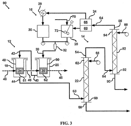
[0022] FIG. 3 is a schematic illustration of one embodiment of the disclosed system in which the stripping device includes two stripping columns.
[0023] FIG. 4 is a schematic illustration of one embodiment of the disclosed system in which the recycling device includes a recharging column.

[0024] FIG. 5 is a simplified schematic illustration of one embodiment of the disclosed system, which was modeled to optimize process parameters, as described in Example 1.

[0025] FIG. 6A is a plan view of the embodiment illustrated in FIG. 5, including piping.

[0026] FIG. 6B is a schematic illustration of the embodiment illustrated in FIG. 5, including piping.
[0027] FIG. 7A is a plan view of the embodiment illustrated in FIG. 5, including dimensions.

[0028] FIG. 7B is a schematic illustration of the embodiment illustrated in FIG. 5, including dimensions.
[0029] FIG. 8 is a piping and instrumentation diagram of the embodiment illustrated in FIG. 5.

[0030] FIG. 9 is a schematic illustration of an experimental apparatus for stripping gadolinium from a supercritical carbon dioxide phase.

DETAILED DISCUSSION
[0031]Throughout this disclosure, the singular terms "a," "an," and "the" include plural referents unless the context clearly indicates otherwise. Similarly, the word "or" is intended to include "and" unless the context clearly indicates otherwise. Reference to process fluids and other materials used in or generated by the disclosed method or system are intended to include all or any portion of antecedent quantities unless the context clearly indicates otherwise. For example, after the antecedent "a solvent," the term "the solvent" shall refer to all or any portion of the quantity of solvent contemplated by the antecedent unless the context clearly indicates otherwise.
[0032]The following terms may be abbreviated in this disclosure as follows: atmosphere (atm); critical pressure (P.sub.C), critical temperature (T.sub.C), cubic centimeter (cc), deionized water (DIW), ethylenediaminetetraacetic acid (EDTA), gram (g), fluoroacetylacetone (HFA), kilogram (kg), level control valve (LCV), liter (L), liters per hour (LPH), molar (M), nuclear magnetic resonance (NMR), pressure control valve (PCV), pump (P), safety valve (SV), tank (TK), thenoyltrifluoroacetone (TTA), tributylphosphate (TBP), and trioctylphosphineoxide (TOPO).
[0033]Disclosed herein are a method for recovering metal from metal-containing material and a system that can be used with the disclosed method. The disclosed method and system are based on the direct extraction of a metal with an extractant including a liquid or supercritical fluid solvent. Some embodiments of the disclosed method can be used to generate aqueous solutions with high-concentrations of the target metal, such as concentrations greater than about 5% by weight, greater than about 10% by weight or greater than about 12% by weight, from starting materials with relatively low concentrations of the target metal, such as concentrations less than about 30% by weight, less than about 20% by weight or less than about 15% by weight.
[0034]The disclosed method and system are particularly useful for the recovery of uranium from uranium-containing material. As discussed above, conventional approaches to uranium recovery have many disadvantages, including high cost and the generation of large amounts of hazardous waste. Direct extraction with an extractant including a liquid or supercritical-fluid solvent has potential as a cleaner and more efficient alternative to conventional uranium-recovery processes. For example, the disclosed extraction optionally can be performed without a separate nitric acid dissolution step. This reduces or eliminates the generation of gaseous oxides of nitrogen, reduces the amount of nitrate-containing liquid effluent, and reduces the amount and toxicity of the residual solid waste.
[0035]In the extraction of uranium, the disclosed method can be used to generate a high-concentration uranyl nitrate solution that is more efficient to process into a final product than the low-concentration uranyl nitrate solution commonly produced by nitric acid dissolution in the PUREX process. In fact, when the disclosed extraction is applied to a uranium-containing material that contains very few non-uranium contaminants, the uranyl nitrate solution produced by the extraction can, in some cases, be concentrated enough to be converted directly into a final product, such as UO.sub.2, without the need for further treatment.
Method
[0036]Embodiments of a method for the separation and recovery of metal from a metal-containing material using a liquid or supercritical-fluid solvent are disclosed. The disclosed embodiments are particularly well-suited for recovering uranium from uranium-containing material. Some embodiments of the disclosed method include one or more of the following three steps: (1) extraction, (2) stripping, and (3) recycling. These steps are described in greater detail below.
Extraction
[0037]Some embodiments of the disclosed method begin with an extraction step. In this step, the metal-containing material is contacted with an extractant. The extractant can include, for example, a liquid or supercritical fluid solvent, an oxidizing agent and a complexing agent. Many of the solvents that are well suited for the extraction of metals are relatively non-polar. Most effective oxidizing agents, such as nitric acid, are not soluble in non-polar solvents. These oxidizing agents, however, can be made soluble by incorporation into an acid-base complex. For example, when nitric acid is bound to a compound such as TBP, the resulting acid-base complex is highly soluble in several non-polar solvents, including carbon dioxide. TBP therefore is capable of serving as a carrier for introducing nitric acid into the solvent.
[0038]Embodiments of the disclosed extraction can be performed with solvents in either liquid or supercritical fluid form. A compound exists as a supercritical fluid when it is at a temperature and pressure above a critical temperature and pressure characteristic of the compound. FIG. 1 is a phase diagram for carbon dioxide, which shows the conditions necessary to produce liquid carbon dioxide and supercritical carbon dioxide. Materials in a supercritical state exhibit properties of both a gas and a liquid. Supercritical fluids typically are able to act as solvents, like subcritical liquids, while also exhibiting the improved penetration power of gases. This makes supercritical fluids a preferred class of solvents for metal extraction. The disclosed liquid solvents can be gases at room temperature and atmospheric pressure. These solvents are converted into liquids by increasing the pressure and/or decreasing the temperature.
[0039]During the extraction of metals, such as uranium, with an acid-base complex including an oxidizing agent and a complexing agent, the oxidizing agent oxidizes the metal and the complexing agent binds to the metal, rendering it more soluble in the solvent than prior to complexation. After being oxidized, the metal can form stable complexes with the acid-base complex. For example, in the extraction of uranium with nitric acid as the oxidizing agent and TBP as the complexing agent, the uranium may form UO.sub.2(NO.sub.3).sub.2.2TBP. Uranium, gadolinium, plutonium, and many other lanthanides and actinides are capable of binding to large numbers of ligands. The disclosed process is especially well suited for the recovery of these metals. Most other metals do not share this property and are not capable of forming stable complexes with acid-base complexes such as TBP-HNO.sub.3. These metals can be recovered by adding a separate chelating agent to the extractant.
[0040]One goal of the extraction step is to concentrate metal in the phase that includes the complexing agent. If the phase including the complexing agent has a high concentration of the metal to be recovered, the efficiency of the stripping step is improved. One way to increase the concentration of the metal to be recovered in the phase including the complexing agent is to decrease the amount of complexing agent in the extractant to which the metal-containing material is exposed. This method, however, can dramatically increase the required extraction time and therefore decrease the efficiency of the extraction process.
[0041]Similar or superior results can be achieved without compromising efficiency by using a countercurrent extraction process. The disclosed countercurrent extraction process is a departure from conventional, single-batch extraction processes. In a single-batch process, the concentration gradient between the metal-containing material and the phase including the complexing agent decreases over time. The disclosed countercurrent extraction process maintains the concentration gradient by moving the extractant and the metal-containing material during the extraction.
[0042]In some embodiments of the disclosed countercurrent extraction process, the extractant is moved through the extraction process in a first direction and the metal-containing material is moved though the extraction process in a second direction, opposite to the first direction. As the extractant moves in the first direction, the concentration of metal in the phase including the complexing agent increases. As the metal-containing material moves in the second direction, the concentration of metal in the metal-containing material decreases. Thus, the metal-containing material with the highest concentration of metal; i.e. the metal-containing material that has not yet been exposed to the extractant, first is exposed to extractant that has already been used to extract the metal from each of the other batches in the series. Only metal-containing material with a high metal concentration is capable of loading this used extractant with additional metal. Similarly, at the other end of the series, the metal-containing material with the lowest concentration of the metal is exposed to fresh extractant; otherwise, there would be an insufficient concentration gradient to drive the extraction. The countercurrent operation allows the disclosed process to maintain a concentration gradient between the metal-containing material and the phase including the complexing agent throughout the process.
[0043]Some embodiments of the disclosed countercurrent extraction process are multi-stage, semi-batch processes. Multi-stage, semi-batch processes can be useful, for example, where the metal-containing material is difficult to move continuously or where the extraction requires long periods of contact between the metal-containing material and the extractant. In some disclosed embodiments, batches of the metal-containing material are placed in separate extraction stations. The extractant is introduced into these stations in series, with the used extractant from one station feeding the next station in a first order. The extractant can be moved continuously or it can be held at each station for an extraction period before being released into the next station. As the metal is recovered from the metal-containing material, the batches of metal-containing material can be moved from one extraction station to the next extraction station in a second order opposite to the first order. When the batches of metal have reached the end of the series of stations, the metal-containing material is at least partially depleted of the metal and can be referred to as residue. The residue is less toxic than the metal-containing material prior to extraction and its disposal is less problematic.
[0044]Multi-stage, semi-batch embodiments of the disclosed extraction step can be used with any number of stations. In general, using a larger number of stations will result in a more complete separation. The completeness of the separation also can be dependent on the extraction time. In some embodiments, the batches of metal-containing material remain in each station for a set amount of time or for a time period effective to remove a certain amount of metal. In total, the metal-containing material can be, for example, exposed to the extractant for variable time periods, as would be understood by a person of ordinary skill in the art. Generally, the time period is between about 30 minutes and about 120 minutes, typically between about 40 minutes and about 100 minutes or more typically between about 50 minutes and about 80 minutes. The flow rate of the extractant through the extraction step can be, for example, between about 2 liters per hour and about 10 liters per hour, typically between about 3 liters per hour and about 8 liters per hour or more typically between about 4 liters per hour and about 7 liters per hour. The extraction step can be configured to recover varying amounts of the metal in the metal-containing material, such as between about 60% and about 100% of the metal, typically between about 80% and about 100% of the metal or more typically between about 85% and about 100% of the metal.
Stripping
[0045]Some embodiments of the disclosed method include a stripping step after the extraction step. After extracting the metal from the metal-containing material and completing the overall extraction step, the extractant can be referred to as an extract. The extract typically contains the solvent and complexes including the metal and the acid-base complex. The stripping step is intended to separate the metal from the extract. Stripping can be accomplished, for example, by exposing the extract to a stripping agent that has a higher affinity for metal than the extract. By way of theory, and without limiting disclosed embodiments to such theory, the oxidizing agent in the extract typically has a high affinity for the stripping agent and is the first component of the extract to be separated. As the concentration of the oxidizing agent decreases, the metal-containing complexes disassociate and the metal ions migrate into the stripping agent. In order to keep the stripping agent separate from the extract, it is helpful to select a stripping agent that is immiscible with, or at least separable from, the extract.
[0046]If two or more different metals are present in the extract, the stripping step also may be useful for separating these metals from each other. Metal ions with different charges, for example, form complexes with different numbers of acid-base complexes and, therefore, may separate from their associated acid-base complexes at different pH values. The pH of the extract can be determined primarily by the concentration of the oxidizing agent. Metals with higher charges require a larger number of anions to neutralize their charge and may disassociate from their respective metal-containing complexes at higher concentrations of the oxidizing agent.
[0047]Separating different metals in the extract from each other is particularly useful for processing spent nuclear fuel rods and other waste material that contains both uranium and gadolinium. Gadolinium-containing particles commonly are introduced into fuel rods as burnable poison to contain fission products. Both uranium and gadolinium form stable complexes with acid-base complexes, such as TBP-HNO.sub.3, at high concentrations of the oxidizing agent and can thereby be solubilized in non-polar solvents, such as supercritical carbon dioxide. The uranium ion, however, typically has a plus two charge, while the gadolinium ion typically has a plus three charge. If the acid anion of the oxidizing agent has a plus one charge, uranium will associate with two acid-base complexes, while gadolinium will associate with three acid-base complexes. In the stripping step, as the oxidizing agent migrates into the stripping agent, the gadolinium-containing complexes will disassociate before the uranium-containing complexes. The uranium and gadolinium therefore can be separated by fractioning the strip product. In some embodiments, the gadolinium enters the stripping agent when the concentration of the oxidizing agent in the extract is between about 2 M and about 3 M and the uranium enters the stripping agent when the concentration of the oxidizing agent in the extract is between about 0.1 M and about 0.5 M.
[0048]Before and during the stripping step, the solvent can be in liquid or supercritical form. In some embodiments, the solvent is maintained in liquid form because the improved penetration power of a supercritical-fluid solvent is no longer necessary. To provide adequate volumes for the stripping step, the solvent can be separated from the extract and replaced with new solvent flowing in a continuous stream.
[0049]The stripping step can be a countercurrent process. While the extract is moving through the process in a first direction, the stripping agent is moving through the process in a second direction opposite to the first direction. The stripping agent often has a greater affinity for the oxidizing agent than for the metal. For example, the solubility of nitric acid in certain aqueous stripping agents, such as water, is greater than the solubility of uranyl ions in these stripping agents. In addition to maximizing the concentration gradient, the countercurrent design can allow both the oxidizing agent and the metal to be removed. In contrast, if both liquids move in the same direction, the stripping agent quickly would become loaded with the oxidizing agent and then would be incapable of removing a significant quantity of the metal.
[0050]Where the solubility difference between the oxidizing agent and the metal is particularly high, it may be useful to separate the stripping step into two or more stages. In a first stage, for example, the solute with the higher solubility in the stripping agent, such as the oxidizing agent, can be removed. Then, the extract can be routed into a second stage in which fresh stripping agent is used to remove the less soluble component, such as the metal. In this way, the presence of the more soluble component does not significantly inhibit the removal of the less soluble component. Multiple stages also may be useful for separating different metals that enter the stripping agent under different conditions and at different times during the stripping process, such as uranium and gadolinium.
[0051]The efficiency of the stripping process is affected by the amount of contact between the stripping agent and the extract. Because the stripping agent and the extract usually are immiscible, achieving this contact can be difficult. In some disclosed embodiments, the stripping agent is sprayed into the extract. The spraying action creates small droplets with a collective surface area far greater than the surface area of larger masses of liquid. The larger surface area of the droplets serves as a larger interface between the stripping agent and the extract, which improves the rate of mass transfer. In some disclosed embodiments, the extract flows through a high-surface-area stripping medium that helps to prevent the droplets from coalescing prematurely.
[0052]After gathering the metal, the stripping agent can exit the stripping step as a strip product. The solvent exits the stripping step with the complexing agent as a raffinate. In one embodiment where the metal is uranium, the stripping agent is water and the oxidizing agent is nitric acid, the strip product can be a concentrated uranyl nitrate solution. Direct dissolution of uranium-containing material with nitric acid, such as in the PUREX process, also can produce a uranyl nitrate solution, but the uranyl nitrate solution produced by the disclosed method typically is much more concentrated than that produced by the PUREX process. Thus, fewer additional steps, if any, are needed before the uranyl nitrate solution produced by the disclosed method can be converted into an end product, such as UO.sub.2. In contrast, the uranyl nitrate solution produced by the PUREX process typically is dilute and requires additional steps, such as additional liquid-liquid extractions, to concentrate the uranium. This is particularly true when the PUREX process is applied to recover uranium from materials with a relatively low concentration of uranium, such as incinerator ash, and when the PUREX process is applied to recover uranium from materials containing an additional metal, such as gadolinium.
[0053]The flow rates of the extractant and the stripping agent can affect the amount of metal removed from the phase including the complexing agent. The flow rate of the extractant can be, for example, between about 10 liters per hour and about 100 liters per hour, between about 15 liters per hour and about 50 liters per hour or between about 20 liters per hour and about 30 liters per hour. The flow rate of the stripping agent can be, for example, between about 1 liter per hour and about 8 liters per hour, between about 1.5 liters per hour and about 5 liters per hour or between about 2 liters per hour and about 3 liters per hour. The total cycle time for the stripping step can be, for example, between about 30 minutes and about 120 minutes, between about 40 minutes and about 100 minutes or between about 50 minutes and about 80 minutes. The amount of metal removed from the extractant can be, for example, between about 50% and about 100%, between about 70% and about 100% or between about 90% and about 100%.
Recycling
[0054]Some embodiments of the disclosed method include a recycling step. Recycling limits the amount of hazardous waste produced by the process and has the potential to reduce the overall cost of the process. The recycling step can include recycling various materials used or formed during the process, such as the complexing agent, the solvent, or both. As mentioned above, in some disclosed embodiments, the complexing agent and the solvent exit the stripping step as a raffinate. This raffinate is different from the extractant in that at least a portion of the oxidizing agent has been consumed. Thus, the raffinate typically is not recycled directly into the extraction step without additional processing.
[0055]In some disclosed embodiments, the solvent is separated from the complexing agent by reducing the pressure and/or increasing the temperature of the raffinate. After the separation, the solvent from the raffinate becomes a recovered gas and the complexing agent from the raffinate becomes a recovered complexing agent. The recovered complexing agent can be combined with the oxidizing agent to form a recovered acid-base complex. The recovered gas can be condensed to form a recovered solvent in liquid or supercritical fluid form. The recovered acid-base complex can be combined either with the recovered solvent or with fresh solvent to form a recovered extractant. After it has been prepared, the recovered extractant can be reintroduced into the process at the extraction step, as described above.
[0056]In embodiments that include a recycling step, the efficiency of the stripping step affects the efficiency of the extraction step. Typically, the stripping step does not remove 100% of the metal from the phase including the complexing agent. The remaining metal is carried in the raffinate and then incorporated into the recovered complexing agent, the recovered acid-base complex and the recovered extractant. The presence of metal in the extractant decreases the efficiency of the extraction step. It is useful, therefore to separate as much metal as possible in the stripping step.
[0057]Another approach to the recycling step is to recharge the raffinate with oxidizing agent without separating the solvent. For example, the raffinate can be introduced into one end of a countercurrent column while the oxidizing agent is introduced into the opposite end. As the raffinate contacts the oxidizing agent within the column, any complexing agent present can combine with the oxidizing agent to reform the acid-base complex. The recharged raffinate then can be routed to the extraction step and used as a recovered extractant.
System
[0058]FIG. 2 illustrates one embodiment of the disclosed system for recovering a metal from a metal-containing material. The system 10 shown in FIG. 2 includes an extraction device 12, a stripping device 14 and a recycling device 16. The extraction device 12 includes a first station 18 and a second station 20. The stripping device 14 includes a stripping column 22. The recycling device 16 includes a separator 24, an acid-base complex mixer 26, a condenser 28, a solvent tank 30 and a static mixer 32.
[0059]In operation, the first station 18 contains a first batch of metal-containing material 34 and the second station 20 contains a second batch of metal-containing material 36. Extractant enters the second station 20 via a second station extractant inlet 38. After extracting metal from the second batch of metal-containing material 36, the extractant exits the second station 20 via a second station extractant outlet 40 and is routed into the first station 18 through the first station extractant inlet 42. After extracting metal from the first batch of metal-containing material 34, the extractant exits the first station 18 via a first station extractant outlet 44. During the extraction, the second batch of metal-containing material 36 is moved out of the second station 20 and then to further processing or disposal. The first batch of metal-containing material 34 is moved out of the first station 18 and into the second station 20. In general, extractant moves through the extraction step in a first direction and metal-containing material moves thorough the extraction step in a second direction opposite to the first direction and indicated by arrows 46.
[0060]Movement of the metal-containing material 34, 36 is facilitated by a first container 48 and a second container 50, located in the first and second stations 18, 20, respectively. The first and second containers 48, 50 are removable and interchangeable between the first and second stations 18, 20. The first and second containers 48, 50 also are configured to maximize contact between the extractant and the metal-containing material 34, 36. The first and second containers 48, 50 both are elongated. The extractant is routed directly into the first and second containers 48, 50 at their top ends and is forced to travel along the length of each container through the metal-containing material until it reaches a first and second filter 51, 52 positioned at the bottom of the first and second containers 48, 50, respectively. The first and second filters 51, 52 allow passage of the extractant, while blocking passage of the metal-containing material.
[0061]After the extractant leaves the extraction device 12 it can be referred to as an extract. The extract enters the stripping column 22 at an extract inlet 53. As the extract moves up the stripping column 22 toward a raffinate outlet 54, a stripping agent moves down the stripping column 22 from a stripping agent inlet 56 to a strip product outlet 58. The extract inlet 53 and the strip product outlet 58 are located near a first end 60 of the stripping column 22. The raffinate outlet 54 and the stripping agent inlet 56 are located near a second end 62 of the stripping column 22. The first end 60 of the stripping column 22 and the second end 62 of the stripping column 22 are the bottom and top ends, respectively.
[0062]The strip product exiting the stripping column 22 moves on for further processing. The raffinate moves into the recycling device 16. The raffinate first enters the separator 24 through a separator raffinate inlet 64. Within the separator 24, the pressure is reduced and the raffinate is separated into a recovered gas 66 and a recovered complexing agent 68. The recovered gas 66 exits the separator 24 and then flows into the condenser 28. The condenser 28 converts the recovered gas 66 into a recovered solvent that flows into the solvent tank 30. Meanwhile, the recovered complexing agent 68 flows out of the separator 24 and into the acid-base complex mixer 26. An oxidizing agent enters the acid-base complex mixer 26 through an acid-base complex mixer oxidizing agent inlet 70. A mixer 72 combines the oxidizing agent and the recovered complexing agent to form a recovered acid-base complex. The recovered acid-base complex exits the acid-base mixer 26 and is combined with the recovered solvent exiting the solvent tank 30 with the static mixer 32. After being mixed by the static mixer 32, the recovered solvent and the recovered complexing agent 68 form a recovered extractant, which flows into the extraction device 12 at the second station extractant inlet 38.
[0063]FIG. 3 illustrates a system 80, which is another embodiment of the disclosed system for recovering a metal from a metal-containing material. The reference numerals from FIG. 2 are repeated in FIG. 3 to indicate similar or identical elements. The main difference between the system 80 in FIG. 3 and the system 10 in FIG. 2 is that the stripping device 14 in the system 80 in FIG. 3 includes first and second stripping columns 22, 82, whereas the stripping device 14 in the system 10 in FIG. 2 only includes one stripping column 22. In the system 80, the raffinate from the first stripping column 22 is exposed to fresh stripping agent in the second stripping column 82.
[0064]With regard to FIG. 3, after it leaves the first stripping column 22, the raffinate can be referred to as an intermediate raffinate. The intermediate raffinate is routed into the second stripping column 82 through an intermediate raffinate inlet 84. As the intermediate raffinate moves up the second stripping column 82 toward a final raffinate outlet 86, the stripping agent moves down the second stripping column 82 from a second stripping agent inlet 88 to a second strip product outlet 90. The intermediate raffinate inlet 84 and the second strip product outlet 90 are located near a first end 92 of the second stripping column 82. The final raffinate outlet 86 and the second stripping agent inlet 88 are located near a second end 94 of the second stripping column 82. The first end 92 of the second stripping column 82 and the second end 94 of the second stripping column 82 are the bottom and top ends, respectively. From the second stripping column 82, the final raffinate is routed into the separator 24 through the separator raffinate inlet 64. The strip product from the first stripping column 22 and the strip product from the second stripping column 82 typically are processed separately. Alternatively, the strip products can be combined for further processing.
[0065]FIG. 4 illustrates yet another embodiment of the disclosed system. The reference numerals from FIGS. 2 and 3 are repeated in FIG. 4 to indicate similar or identical elements. The system 100 is similar to the system 80 illustrated in FIG. 3, except with respect to the recycling device 16. In the system 100, the recycling device 16 includes a recharging column 102 configured to receive the raffinate exiting the second stripping column 82. The recharging column 102 has a first end 104 and a second end 106. The raffinate enters the recharging column 102 at a recharging column raffinate inlet 108 located near the first end 104 of the recharging column 102. Oxidizing agent enters the recharging column 102 at a recharging column oxidizing agent inlet 110 located near the second end 106 of the recharging column 102. As the raffinate contacts the oxidizing agent within the recharging column 102, the complexing agent within the raffinate combines with the oxidizing agent to reform the acid-base complex. A recovered extractant including the solvent and the reformed acid-base complex then exits the recharging column 102 at a recovered extractant outlet 112 located near the second end 106 of the recharging column 102. Excess oxidizing agent exits the recharging column 102 at an excess oxidizing agent outlet 114 located near the first end 104 of the recharging column 102.
[0066]After exiting the recharging column 102, the excess oxidizing agent is routed to the stripping agent inlet 56 of the stripping column 22. The recovered extractant is routed into a surge tank 116. If necessary, make-up solvent and/or complexing agent can be added to the surge tank 116 through a make-up solvent/complexing agent inlet 118. From the surge tank 116, the recovered extractant flows into the second station 20 of the extraction device 12. A booster pump can be included near the surge tank 116 to provide the necessary motive force.
[0067]The embodiments illustrated in FIGS. 2-4 are merely exemplary. This disclosure also describes additional embodiments not limited to the particular features illustrated in FIGS. 2-4. As illustrated in FIGS. 2-4, embodiments of the system can include several devices that work together to perform the overall extraction. Three of these devices are discussed in the following subsections.
Extraction Device
[0068]As discussed above, a first step in the recovery of a metal from a metal-containing material can be an extraction step. In some embodiments of the disclosed method, extraction is performed by exposing the metal-containing material to an extractant including a liquid or supercritical fluid solvent. In addition to the solvent, the extractant can include an acid-base complex including an oxidizing agent and a complexing agent. Some embodiments of the disclosed system include an extraction device, such as extraction device 12, for carrying out the extraction step.
[0069]The extraction device can be designed for the extraction of metals, such as uranium, from solid materials, such as incinerator ash. Solid materials can be difficult to move through continuous processes, so most conventional extraction processes involving solid materials are batch processes. Batch processes also make it easier to expose the metal-containing material to the extractant for long periods of time. Batch processes, however, often are characterized by lower extraction efficiencies than continuous processes. This is because, as discussed above, batch processes are less effective at maintaining a concentration gradient between the extractant and the metal-containing material than countercurrent processes.
[0070]Many of the advantages of batch processing can be achieved without unduly sacrificing extraction efficiency by using a semi-batch process. Some embodiments of the disclosed extraction device include two or more extraction stations, each of which operates in a manner similar to a single batch extraction device. The extractant can be routed through these stations in series. Meanwhile, the batches of metal-containing material can be moved between the stations in an order countercurrent to the order in which extractant is moved. The countercurrent operation allows the disclosed process to maintain a concentration gradient between the metal-containing material and the extractant throughout the process.
[0071]Embodiments of the disclosed extraction device can include a network of piping routed through the stations in series. At one end of the series, an extractant inlet can be positioned to receive the extractant, e.g. from the recycling device. At the opposite end of the series an extractant outlet can be positioned to release the extractant, e.g. to the stripping device. Between the stations, pipes can be positioned to route used extractant from one station to the next station in series.
[0072]Each station can include a container for holding metal-containing material, such as solid metal-containing material. The containers, for example, can be cylindrical with solid walls and a bottom that is permeable to the extractant. The extractant can be introduced at the top of these containers so that it is forced to flow through the metal-containing material before it exits at the bottom of the container. The permeable portions of the container can be made of any useful material, such as sintered metal, which is permeable to liquids and gases, but not permeable to solids. After it flows through the container, the extractant can flow into the portion of the station external to the container before it is released through the station's extract outlet.
[0073]The stations in some embodiments of the disclosed extraction device are configured to allow the batches of metal-containing material to be transported between the stations. For example, the containers within the stations can be removable and interchangeable. In this way, the container in one station can be removed from that station with its batch of metal-containing material and then moved into the next station in the series. The batch of metal-containing material in the container at the end of the series can removed for disposal or further processing. The container at the end of the series then can be filled with raw metal-containing material and introduced into the first station in the series. Movement of the containers can be facilitated, for example, with handles designed to be gripped by a human or robotic operator.
[0074]Is some disclosed embodiments, the stations are configured to promote the extraction process by providing agitation. Agitation can be provided by any suitable means, including physical mixing and ultrasonic vibration. For example, one or more of the stations can be equipped with a magnetic stir bar or an ultrasound emitting device operable to apply ultrasonic vibrations to contents contained in the interior of the station.
[0075]The solvents well-suited for use in the disclosed process typically are gases at room temperature and atmospheric pressure. Maintaining these solvents in liquid form requires high pressures and/or low temperatures. Maintaining these solvents in supercritical fluid form requires high pressures and can require elevated temperatures depending on the critical temperature of the solvent. Some embodiments of the disclosed extraction device include stations that are configured to withstand high pressures, such as pressures greater than about 20 atm, about 50 atm or about 200 atm. For example, these stations can have rounded walls that are thick enough to withstand the high pressures. The extraction device also can include chillers and/or heaters to maintain the extractant at the proper temperature, such as above its critical temperature if the solvent is to be maintained in supercritical fluid form. The extraction device also can be insulated.
[0076]In some disclosed embodiments, the containers within the stations are designed to be moved after the stations have been evacuated. To allow this, the extractant inlets and outlets on each station can be fully closed to isolate each station from the extractant. The stations also can be isolated in this manner to allow the metal-containing material to soak in a volume of extractant for an extended period of time.
Stripping Device
[0077]In some embodiments of the disclosed method, the metal from the metal-containing material is made soluble in the solvent by oxidation and complexation with a complexing agent. The metal in the extract can be bound within complexes including the complexing agent and/or the oxidizing agent. Some embodiments of the disclosed system include a stripping device configured to separate the metal from one or more of the solvent, the complexing agent, the oxidizing agent and other metals. The stripping device, for example, can be configured to expose the extract exiting the extraction step to a stripping agent.
[0078]The stripping device can include a stripping column, such as a countercurrent stripping column. The extract can be introduced into the column at an extract inlet and then exit the column, after being depleted of metal, at a raffinate outlet. The extract inlet and the raffinate outlet typically are at opposite ends of the column. In a similar manner, the stripping agent can be introduced into the column at a stripping agent inlet and then exit the column, after gaining metal, at a strip product outlet. Like the extract inlet and the raffinate outlet, the stripping agent inlet and the strip product outlet typically are at opposite ends of the column. In embodiments in which the stripping column is configured for countercurrent operation, the extract inlet and the strip product outlet can be positioned near a first end of the column and the stripping agent inlet and the raffinate outlet can be positioned near a second end of the column opposite to the first end. Whether the first and second ends are the top and bottom ends, respectively, or the bottom and top ends, respectively, depends on the relative densities of the extract and the stripping agent. For example, if the stripping agent has a higher density than the extract, it will be pulled down by the force of gravity, so the first end, which includes the strip product outlet, can be the bottom end of the column and the second end, which includes the stripping agent inlet, can be the top end of the column.
[0079]Countercurrent operation is particularly useful if there is a difference in the affinity of the stripping agent for the oxidizing agent versus the metal. For example, in a countercurrent stripping column, if the stripping agent has a higher affinity for the oxidizing agent than for the metal, the oxidizing agent is removed from the extract near the point at which the extract enters the column. As the extract moves through the column it becomes depleted of the oxidizing agent and begins to contact the stripping agent closer to the point at which the stripping agent enters the column. Therefore, the extract contacts the freshest stripping agent after the oxidizing agent has been significantly depleted. The gradual depletion of the oxidizing agent also can facilitate the separate removal of different metals, such as uranium and gadolinium.
[0080]In some disclosed embodiments, the stripping device includes two or more stripping columns. This is especially useful if the stripping agent cannot easily be loaded with both the metal and the oxidizing agent. For example, in some applications, the presence of one solute in the stripping agent significantly affects the ability of the stripping agent to remove the other solute from the extract. In the first stripping column, the extract can be depleted of the component with a higher solubility in the stripping agent. An intermediate raffinate exiting the first stripping column then can be routed into the second stripping column where fresh stripping agent can be introduced to separate the component with a lower solubility in the stripping agent. The strip product from both stripping columns then can be combined.
[0081]Separate stripping columns also can be used to facilitate the separation of different metals within the extract, such as uranium and gadolinium. The metal that enters the stripping agent first can be removed in a first strip product from the first column and the metal that enters the stripping agent later can be removed in a second strip product from the second stripping column. Where the first and second strip products contain different metals, they typically are processed separately, rather than combined.
[0082]Embodiments of the disclosed stripping device typically are configured for liquid-liquid stripping processes. These processes rely on solubility differences between two immiscible liquids to drive the solute from one liquid into the other. The rate of mass transfer is improved by increasing the amount of contact between the two liquids. This can be done, for example, by vigorously mixing the liquids or by introducing one liquid into the column as droplets. The surface area of small droplets of liquid is far greater than the surface area of the same volume of liquid in a unified clump or stream. The liquid in droplet form can be referred to as the dispersed phase. Embodiments of the disclosed stripping device typically are configured to introduce the stripping agent as the dispersed phase.
[0083]One way to separate a liquid into small droplets is to pass the liquid through a sprayer. In some embodiments of the disclosed stripping device, the stripping agent is sprayed into the stripping column with a sprayer. The stripping column can have one sprayer or multiple sprayers distributed along the length of the column. Multiple sprayers allow fresh stripping agent to be introduced at different points throughout the column. In some disclosed embodiments, the stripping agent is sprayed into the extract as the extract flows through the column in an upward direction, such that droplets of stripping agent are suspended within the extract and move in a downward direction opposite to the direction of the extract by the force of gravity. The extract collects at the top end of the stripping column and exits at the top of the stripping column. Droplets of stripping agent coalesce into a pool at the bottom of the stripping column. The pools of extract and stripping agent at the ends of the stripping column tend to be relatively homogeneous because of the immiscibility of the liquids. The size of the stripping agent pool can be controlled by adjusting the flow rate of the stripping agent out of the stripping column and maintaining a constant interface between the two phases at the bottom of the column.
[0084]Droplets of a liquid floating in an immiscible liquid tend to gravitate towards each other over time. In some disclosed embodiments, this process is delayed by incorporating a high-surface area stripping medium into the stripping column. A high-surface area stripping medium can serve to attract the small droplets and thereby delay their conglomeration. One example of a high-surface-area stripping medium suitable for prolonging the separation of immiscible liquids is fiber mesh. The fiber mesh can be made from any suitable material, such as metal (e.g. stainless steel) or plastic. The mesh can terminate near the inlets for the extract and the stripping agent to allow the stripping agent to pool beyond the extract inlet and the extract to pool beyond the stripping agent inlet. Another way to prolong the separation of the liquids is to recollect the dispersed phase at several points along the length of the column and then spray it back into the column after each collection point. Alternately, the liquid in the stripping column can be pulsed to force coalesced dispersed phase droplets through intermediate perforated plates to reform small droplets of the dispersed phase.
[0085]It is beneficial for the extract to include the solvent in order to maintain a sufficient density difference between the phases to allow for proper column operation and phase separation. It can be important to prevent the solvent from evaporating significantly before or during the stripping step. It can be useful, therefore, to maintain the solvent in liquid or supercritical fluid form before and during the stripping step. Most of the solvents used with the disclosed method require high pressures and/or low temperatures to remain in liquid form. In order to maintain the solvents in supercritical form, high pressures and elevated temperatures typically are required. Like the extraction stations, embodiments of the stripping column can be configured to maintain the solvent at high pressures, such as pressures greater than about 20 atm, about 50 atm or about 200 atm. The stripping column can, for example, include reinforced, rounded walls.
[0086]In embodiments in which the stripping agent is sprayed into the column, the stripping agent inlet can be a high-pressure sprayer. The source of the stripping agent can be at a high enough pressure to spray the stripping agent into the column without significant backflow. For example, backflow desirably may be minimized or substantially eliminated, especially where the stripping agent is water and the stripping column is attached to a shared water supply. As a precaution, some disclosed embodiments are supplied with a stripping agent that is stored in a dedicated stripping agent supply tank. Embodiments of the stripping device also can be configured to maintain the extract at the proper temperature, such as with insulation and chillers or heaters.
Recycling Device
[0087]To minimize the amount of liquid waste and to save on the cost of materials, some embodiments of the disclosed method incorporate a recycling step. This step can be carried out by a recycling device. The recycling device can be configured to recycle the complexing agent, the solvent or both. With the disclosed recycling device, the disclosed system can be highly contained, with little need for make-up solvent or make-up complexing agent.
[0088]The complexing agent and the solvent typically are present in a single phase before the recycling step. In some disclosed embodiments, the solvent is separated from the complexing agent before they are recycled, so that the complexing agent can be recharged with the oxidizing agent to replace the oxidizing agent consumed in the extraction step. The result is the formation of a recycled acid-base complex. In other embodiments, the acid-base complex is reformed without separating the complexing agent from the solvent. In these embodiments, the solvent can remain in liquid or supercritical fluid form at all times, except, for example, when the process is shut down for maintenance.
[0089]In some disclosed embodiments, a raffinate, such as the raffinate exiting the stripping device, enters a separator. The separator separates the solvent from the complexing agent by decreasing the pressure and/or increasing the temperature of the raffinate. Solvents for use with the disclosed process can be selected to evaporate at higher pressures and/or lower temperatures than the pressures and temperatures at which the complexing agents evaporate. For example, most of the disclosed solvents are gases at room temperature and atmospheric pressure, while most of the disclosed complexing agents are liquids at room temperature and atmospheric pressure. For most of the disclosed combinations of solvents and complexing agents, decreasing the pressure is a simple and efficient way to effect a virtually complete separation.
[0090]Separators for use with disclosed embodiments of the recycling device can reduce the pressure of the raffinate, for example, with a let-down valve. The let-down valve can be positioned near an inlet to an expansion tank. In some disclosed embodiments, the solvent is vented to the atmosphere or vented to a pollution control device. In other disclosed embodiments, some or all of the solvent is recycled.
[0091]The liquid outlet of the separator can be routed into an acid-base complex mixer. Within the acid-base complex mixer, the recovered complexing agent can be mixed with fresh oxidizing agent entering from an oxidizing agent source. The acid-base complex mixer typically does not need to be at high pressure because the recovered complexing agent and the oxidizing agent typically are liquids at room temperature and atmospheric pressure. In some disclosed embodiments, the acid-base complex mixer includes a tank with a mechanical mixing device. Typically the complexing agent and the oxidizing agent are miscible and only a limited amount of mixing is required.
[0092]In embodiments in which the solvent is recycled, the solvent exiting the separator as a gas can be converted into a recovered liquid or supercritical-fluid solvent. This can be done, for example, by decreasing the temperature and/or increasing the pressure of the solvent. Less energy is used by this process if the solvent is maintained at a relatively high pressure and/or low temperature after being separated from the complexing agent. For example, the separator can be configured to decrease the pressure and/or increase the temperature of the raffinate only as much as is required to perform the separation. If the solvent exiting the separator in gas form is at a high enough pressure, it may be possible to convert the solvent back into liquid or supercritical fluid form solely by decreasing its temperature in a condenser.
[0093]After the recovered complexing agent has been combined with the oxidizing agent to form a recovered acid-base complex and the solvent has been converted back into liquid or supercritical fluid form, the recovered liquid or supercritical-fluid solvent can be combined with the recovered acid-base complex to form a recovered extractant. This combination step typically occurs at high pressure because the solvent must be maintained in liquid or supercritical fluid form. In some disclosed embodiments, the recovered liquid or supercritical-fluid solvent is mixed with the recovered acid-base complex in a static mixer. The static mixer can be any device capable of mixing the recovered liquid or supercritical-fluid solvent and the recovered acid-base complex with few or no moving parts. Some static mixers include pipes with fixed internal components, such as blades, that agitate the liquids as the liquids flow through the mixer. Static mixers are well suited for mixing fluids at high pressure. In contrast, non-static mixers, such as mixers with mixing blades that rotate, tend to be unreliable at high pressures.
[0094]Embodiments of the disclosed system configured to reform the acid-base pair without separating the complexing agent from the solvent can include a recharging column. The recharging column can be configured to mix the raffinate with fresh oxidizing agent so as to allow any complexing agent present to recombine with the oxidizing agent and thereby reform the acid-base pair. The solvent and the reformed acid-base pair can exit the recharging column as a recovered extractant. Excess oxidizing agent can be used as a stripping agent in one of the upstream stripping columns. For example, the excess oxidizing agent can be introduced into a first stripping column configured to separate a metal that disassociates with the acid-base complex at a lower pH than a second metal. A stripping agent with a higher pH then can be used in a second stripping column downstream from the first stripping column to separate the second metal.
[0095]After it is formed, either with or without separation of the complexing agent from the solvent, the recovered extractant can be routed directly into the extraction device, as discussed above. Make-up solvent and/or complexing agent also can be added, if necessary. In some embodiments of the disclosed system a valve between the recycling device and the extraction device allows for precise control of the flow rate of the recovered extractant entering the extraction device.
Materials
[0096]The disclosed method and system are highly versatile and capable of using a variety of different materials to serve a variety of functions. Some of the classes of materials that can be used with the disclosed method and system are discussed in greater detain below.
Metal and Metal-Containing Material
[0097]The disclosed method and system can be used to recover a variety of metals from a variety of metal-containing materials. Different metals can be targeted, for example, by changing the oxidizing agent, the complexing agent, the stripping agent, or any combination thereof. Among complexing agents, for example, TBP is well suited for the recovery of lanthanides and actinides, such as uranium, gadolinium and plutonium.
[0098]Many of the metals that can be recovered with embodiments of the disclosed method and system are metals that are capable of bonding to large numbers of ligands. Among these metals are lanthanides and actinides, such as uranium, gadolinium and plutonium. These metals typically form stable complexes with acid-base complexes, such as TBP-HNO.sub.3. Some metals that are not capable of bonding to large numbers of ligands can be extracted by adding a separate chelating agent to the extractant. These metals can be oxidized by the acid-base complex and then complexed with the chelating agent to become soluble in non-polar solvents, such as liquid or supercritical carbon dioxide. The stripping step and the stripping device discussed above can be modified to separate the metals from metal-containing complexes that include the chelating agent.
[0099]Some of the metals that are not capable of binding to large numbers of ligands are noble metals, platinum group metals and coinage metals. Noble metals, in general, are metals that are resistant to oxidation. The noble metals are gold, silver, palladium, platinum, rhodium, rhodium, iridium, and osmium. The platinum group metals are platinum, palladium, iridium, rhodium, ruthenium and osmium. The coinage metals are copper, gold, nickel, silver and platinum.
[0100]Some embodiments of the disclosed method and system are especially well suited for the recovery of uranium, gadolinium and plutonium from materials that contain one or more of these metals. These metals can be separated from each other during the stripping step, as discussed above, or recovered together and then separated from each other by subsequent liquid-liquid extractions, such as liquid-liquid extractions based on the relative affinity of the metals for TBP.
[0101]The metal-containing material from which the metal is recovered can take many forms. In most cases, the material is solid, but it also can be liquid. Some examples of solid materials that contain uranium are incinerator ash, spent nuclear fuel, reactor parts from decommissioned nuclear power plants and noncombustible operational waste. The disclosed method and system can be applied to any of these materials, but some disclosed embodiments are specifically configured for recovering metals from incinerator ash. Incinerator ash is highly permeable and easily dividable into batches of approximately equal size.
[0102]The disclosed method and system can be used on materials containing various concentrations of metals to be recovered. Some disclosed embodiments are especially well-suited for recovering metals present at relatively low concentrations, such as metals present at concentrations less than about 30% by weight, less than about 20% by weight or less than about 10% by weight.
Liquid or Supercritical-Fluid Solvent
[0103]In embodiments of the disclosed method, the separation of metals occurs in a liquid or supercritical-fluid solvent. Supercritical-fluid solvents are especially useful because they have greater penetration power than liquid solvents. In some disclosed embodiments the solvent is a gas at room temperature and atmospheric pressure. These solvents are useful, in part, because they can be separated easily from the metal-containing complex by decreasing the pressure and/or increasing the temperature. These solvents also tend to be relatively inert and either non-toxic or less toxic than other solvents.
[0104]Suitable solvents include, but are not limited to, carbon dioxide, nitrogen, nitrous oxide, methane, ethylene, propane and propylene. Carbon dioxide is a preferred solvent for both subcritical and supercritical fluid extractions because of its moderate chemical constants and its inertness. Carbon dioxide has a critical temperature of 31.degree. C. and a critical pressure of 73 atm. Supercritical carbon dioxide is non-explosive and thoroughly safe for extractions. Carbon dioxide also is a preferred solvent because it is abundantly available and relatively inexpensive.
[0105]As mentioned above, supercritical solvents have certain advantages relative to liquid solvents, but liquid solvents still are suitable for many embodiments of the disclosed method. At room temperature, carbon dioxide becomes a liquid above 5.1 atm. Depending on the pressure, liquid carbon dioxide has a density comparable to or slightly greater than the density of supercritical carbon dioxide. Thus, the solvation power of liquid carbon dioxide is comparable to or slightly greater than that of supercritical carbon dioxide. Liquid carbon dioxide is able to dissolve metal-containing complexes, but liquid carbon dioxide does not have the "gas-like" properties of supercritical carbon dioxide. Liquid carbon dioxide has a high viscosity, a low diffusivity, and consequently a poor penetration power compared to supercritical carbon dioxide. The extraction efficiency of liquid carbon dioxide may depend on the applied pressure. In addition, it may be possible to improve the extraction efficiency of liquid carbon dioxide by applying agitation, such as ultrasonic agitation.
[0106]The liquid and supercritical fluid solvents used in embodiments of the disclosed method may be used individually or in combination. Examples of suitable solvents, and their critical temperatures and pressures, are shown in Table 1.
TABLE-US-00001 TABLE 1 Physical Properties of Selected Solvents Molecular Fluid Formula T.sub.C (.degree. C.) P.sub.C (atm) Carbon dioxide CO.sub.2 31.1 72.9 Nitrous oxide N.sub.2O 36.5 71.7 Ammonia NH.sub.3 132.5 112.5 n-Pentane C.sub.5H.sub.12 196.6 33.3 n-Butane C.sub.4H.sub.10 152.0 37.5 n-Propane C.sub.3H.sub.6 96.8 42.0 Sulfur hexafluoride SF.sub.6 45.5 37.1 Xenon Xe 16.6 58.4 Dichlorodifluoromethane CCl.sub.2F.sub.2 111.8 40.7 Trifluoromethane CHF.sub.3 25.9 46.9 Methanol CH.sub.3OH 240.5 78.9 Ethanol C.sub.2H.sub.5OH 243.4 63.0 Isopropanol C.sub.3H.sub.7OH 235.3 47.0 Diethyl ether (C.sub.2H.sub.25).sub.2O 193.6 36.3 Water H.sub.2O 374.1 218.3
[0107]In some embodiments of the disclosed method, a modifier can be added to the solvent to vary the characteristics thereof. For example, a modifier can be added to the solvent to enhance the solubility of a particular complexed metal. Some useful modifiers are low-to-medium boiling point alcohols and esters, such as lower alkyl alcohols and esters. As used herein, the term "lower alkyl" refers to compounds having ten or fewer carbon atoms, and includes both straight-chain and branched-chain compounds and all stereoisomers. Typical modifiers can be selected from the group consisting of methanol, ethanol, ethyl acetate, and combinations thereof. The modifiers are added to the solvent in an amount sufficient to vary the characteristics thereof. This can be an amount, for example, between about 0.1% and about 20% by weight. The modifiers contemplated for use with embodiments of the disclosed method most typically are not supercritical fluids at the disclosed operating conditions. Rather, the modifiers simply are dissolved in the solvents to improve their solvent properties.
Oxidizing Agent
[0108]In some disclosed embodiments, the metal is oxidized with an oxidizing agent during the extraction step. For example, uranium dioxide in the +4 oxidation state does not form stable complexes with most commonly known chelating agents. Thus, it can be useful to use an oxidizing agent to convert uranium dioxide to the +6 oxidation state, which does form stable complexes with a number of complexing agents, including complexing agents, such as TBP, that are soluble in supercritical carbon dioxide.
[0109]Suitable oxidizing agents include Lewis acids, Bronsted-Lowry acids, mineral acids, and combinations thereof. Many of the useful oxidizing agents are non-organic acids. Specific examples include, but are not limited to, nitric acid, sulfuric acid and hydrogen peroxide. The oxidizing agent also can be a non-acid oxidizing agent. In some disclosed embodiments, the oxidizing agent is a compound that, after oxidizing the metal, is converted into products that are easily separable from the metal being extracted. For example, in some disclosed embodiments, the oxidizing agent is selected to break down into volatile and/or soluble products after oxidizing the metal. The oxidizing agent also can be selected to break down into compounds that are gases at room temperature and atmospheric pressure and/or water after oxidizing the metal.
Complexing Agent
[0110]Without the presence of a complexing agent, many oxidizing agents, such as nitric acid, are insoluble in non-polar solvents, such as supercritical carbon dioxide. Complexing agents can be combined with the oxidizing agents to form acid-base complexes that are soluble in non-polar solvents. For example, the solubility of the oxidizing agent in supercritical carbon dioxide can be increased from less than about 0.1 moles per liter at 50.degree. C. and 100 atm to greater than about 0.5 moles per liter at 50.degree. C. and 100 atm by combining the oxidizing agent with a complexing agent to form an acid-base complex.
[0111]Suitable complexing agents to be paired with the oxidizing agents include Lewis bases, Bronsted-Lowry bases, and combinations thereof. Complexing agents that are well suited for use with the disclosed method include Lewis bases soluble in supercritical carbon dioxide, and combinations thereof. Examples include, but are not limited to, alkyl phosphates, including tri-alkyl phosphates, such as TBP, as well as alkylphosphine oxides, including tri-alkylphosphine oxides, such as TOPO. The complexing agent also can be a non-basic complexing agent that is nevertheless capable of forming a complex with an oxidizing agent.
Acid-Base Complex
[0112]As mentioned above, the oxidizing agent and complexing agent can be introduced into the solvent as an acid-base complex. An oxidizing agent, such as nitric acid, can be combined with a complexing agent, such as TBP, to form an acid-base complex that is soluble in non-polar solvents, such as supercritical carbon dioxide. The oxidizing agent typically is the acid component of the acid-base complex, while the complexing agent typically is the base component of the acid-base complex.
[0113]TBP-HNO.sub.3 can be prepared, for example, by mixing TBP with a concentrated nitric acid solution. Nitric acid dissolves in the TBP phase forming a Lewis acid-base complex of the general formula TBP(HNO.sub.3).sub.x(H.sub.2O).sub.y, which is separable from the remaining aqueous phase. The x and y values depend on the relative amount of TBP and nitric acid used in the preparation. TBP-HNO.sub.3 complexes of different x and y values have been characterized by conventional titration methods as well as by proton NMR spectroscopy. Higher x values correspond to increased oxidation strength. In some disclosed embodiments x is greater than or equal to about 0.7 and y is less than or equal to about 0.7.
Chelating Agent
[0114]For the extraction of certain metals it can be useful to incorporate a chelating agent into the extractant. The chelating agent can be selected to solubilize the metal in the solvent after the metal has been oxidized. The use of a chelating agent different than the acid-base complex can be useful for the recovery of metals that do not form stable complexes with the acid-base complex. Beneficial factors to consider in the selection of chelating agents include, but are not limited to, high stability constants of the metal-containing complex formed, fast complexation kinetics, good solubility in the solvent for both the chelating agent and the metal-containing complex formed, and sufficient specificity to allow selective extraction of a metal or a group of metal ions.
[0115]Without limitation, chelating agents for practicing embodiments of the disclosed method include .beta.-diketones, phosphine oxides (such as trialkylphosphine oxides, triarylphosphine oxides, and alkylarylphosphine oxides), phosphinic acids, carboxylic acids, phosphates (such as trialkylphosphates, triarylphosphates, and alkylarylphosphates), crown ethers, dithiocarbamates, phosphine sulfides, phosphorothioic acids, thiophosphinic acids, halogenated analogs of these chelating agents, and mixtures of these chelating agents. Some of the useful chelating agents have lower alkyl functional groups. Alkyl-substituted chelating agents with chain lengths of about eight carbons, especially branched-chain alkyl groups, are characterized by high solubilities in supercritical carbon dioxide.
[0116]A partial list of examples of chelating agents useful for solubilizing metals in non-polar solvents is provided in Table 2.
TABLE-US-00002 TABLE 2 Chelating Agents Oxygen Donating Chelating Agents cupferron chloranilic acid and related reagents .beta.-diketones and related reagents N-benzoyl-N-phenylhydroxylamine and related reagents macrocyclic compounds Nitrogen Donating Chelating Agents .alpha.-dioximines diaminobenzidine and related reagents porphyrins and related reagents Oxygen and Nitrogen Donating Chelating Agents 8-hydroxyquinoline nitrosonapthols and nitrosophenols EDTA diphenylcarbazide and diphenylcarbazone azoazoxy BN octanol-2 methyl isobutyl ketone and related reagents tri-alkyl amines, such as (C.sub.nH.sub.2n+1).sub.3N (n = 8-10), and related reagents tri-octyl amines, such as [CH.sub.3(CH.sub.2).sub.6CH.sub.2].sub.3N, and related reagents Sulfur or Phosphorus Donating Chelating Agents sodium diethyldithiocarbamate and related reagents dithizone and related reagents bismuthiol II thenoyltrifluoroacetone thioxine thiophosphinic acids phosphine sulfides phosphorothioic acids tributyl phosphate and related reagents
Stripping Agent
[0117]The stripping agent can be any liquid that has a higher affinity for the metal than the phase including the complexing agent. Metal ions typically have a higher solubility in an aqueous phase than in an organic phase. Therefore, in some disclosed embodiments, the stripping agent is aqueous. Water can be an effective stripping agent for removing metals, such as uranium, from the phase including the complexing agent, such as TBP. Other polar molecules in liquid form, such as alcohols, also may be suitable stripping agents.
[0118]In selecting a stripping agent, it can be useful to consider the processing required to convert the metal within the striping agent into a final product. In the recovery of uranium, for example, using water as the stripping agent can result in the formation of a uranyl solution, such as a uranyl nitrate solution. This solution then can be converted directly into UO.sub.2.
Operating Conditions
[0119]The operating conditions for the extraction step typically depend on the properties of the solvent, such as the critical temperature and the critical pressure for the solvent. The extraction can be, for example, carried out at a temperature and pressure greater than the triple point for the solvent or greater than the critical point for the solvent. The appropriate temperature and pressure depend on whether the solvent is maintained as a liquid or as a supercritical fluid. In extractions in which the solvent is carbon dioxide and the solvent is maintained as a liquid, the temperature and pressure can be, for example, any temperature and pressure combination in the liquid region of the carbon dioxide phase diagram shown in FIG. 1. If the solvent is maintained as a supercritical fluid, the temperature and pressure can be, for example, any temperature and pressure greater than the temperature and pressure at the critical point of the carbon dioxide phase diagram shown in FIG. 1.
[0120]As with the extraction step, the operating conditions for the stripping step typically depend on the properties of the solvent. Any of the temperature and pressure combinations disclosed for the extraction step also can be applied to the stripping step. In some disclosed embodiments, the stripping step does not benefit significantly from the improved penetration power of supercritical fluids so the solvent is maintained in liquid form.
[0121]The operating conditions can affect the rates of certain reactions in the disclosed method, such as the rate at which the metal is oxidized, the rate at which the metal is complexed and the rate at which the metal is stripped from the metal-containing complex. In general, higher pressures make the solvent denser, which tends to increase the rate of reactions occurring within the solvent. Higher temperatures also tend to increase the rate of these reactions. Therefore, in order to increase reaction rates, some embodiments of the disclosed method are performed at temperatures and pressures higher than the temperatures and pressures required to maintain the solvent in the desired phase. Temperature and pressure are interrelated, so using increased temperatures, for example, may necessitate the use of increased pressures to maintain the solvent in the desired phase and at the desired density.
EXAMPLES
[0122]The following examples are provided to illustrate certain particular embodiments of the disclosure. Additional embodiments not limited to the particular features described are consistent with the following examples.
Example 1
[0123]This example describes several laboratory trials that were performed to study the effect of process conditions on the mass transfer of the metal in the stripping step. In these trials, the metal was uranium, the complexing agent was TBP, the oxidizing agent was nitric acid and the stripping agent was water. Tables 3-7 show the concentrations of uranium and nitric acid before stripping as well as the concentrations of uranium and nitric acid in the organic and aqueous phases after stripping. Each table shows the results of one or more trials performed at a given temperature, pressure and ratio of TBP to water. Two values for each of these variables were tested, with each table showing the data for trials performed at a different combination of values. Comparing the data between the tables indicates the effect of each variable on the mass transfer. Within each table, the individual trials represent different starting concentrations of uranium and nitric acid.
TABLE-US-00003 TABLE 3 Stripping Data at 50.degree. C., 200 bar and TBP:water = 1:1.9 BEFORE AFTER [HNO.sub.3].sub.ini U.sub.org U.sub.aq U.sub.org/ U.sub.aq [HNO.sub.3].sub.aq [HNO.sub.3].sub.org [HNO.sub.3].sub.aq/ [U] (g/L) (mol/L) % U.sub.aq' (g/L) (g/L) Uaq (mol/L) (mol/L) (mol/L) [HNO.sub.3].sub.org 219.03 8.30 39.12 133.3 85.7 1.6 0.360 4.98 6.31 0.79 162.01 6.67 30.86 112.0 50.0 2.2 0.210 4.8 3.55 1.35 107.5 7.10 17.74 88.4 19.1 4.6 0.080 5.4 3.23 1.67 58.71 7.37 4.61 56.0 2.7 20.7 0.011 5.9 2.79 2.11 173.71 4.76 30.95 119.9 53.8 2.2 0.226 3.68 2.05 1.79 109.67 4.70 27.91 79.1 30.6 2.6 0.129 3.3 2.66 1.24 34.12 4.26 23.3 26.2 7.9 3.3 0.033 2.44 3.46 0.71 182.41 3.30 46.61 97.4 85.0 1.1 0.357 2.35 1.81 1.30 129.69 3.30 40.46 77.2 52.5 1.5 0.220 2.26 1.98 1.14 91.45 3.30 31.13 63.0 28.5 2.2 0.120 2.09 2.30 0.91 187.26 2.74 35.38 121.0 66.3 1.8 0.278 1.86 1.67 1.11 65.14 2.82 31.72 44.5 20.7 2.2 0.087 1.88 1.79 1.05 204.86 1.87 56.27 89.6 115.3 0.8 0.484 1.3 1.08 1.20 146.92 1.52 53.34 68.6 78.4 0.9 0.329 0.96 1.06 0.90 111.91 1.87 48.58 57.5 54.4 1.1 0.228 1.25 1.18 1.06 105.64 1.70 56.53 45.9 59.7 0.8 0.251 1.39 0.59 2.36 75.11 1.83 53.97 34.6 40.5 0.9 0.170 1.25 1.10 1.13 204.73 1.21 61.51 78.8 125.9 0.6 0.529 0.96 0.48 2.02 204.73 1.21 60.5 80.9 123.9 0.7 0.520 0.99 0.42 2.37 103.1 0.70 90.83 9.5 93.6 0.1 0.393 0.64 0.11 5.61
TABLE-US-00004 TABLE 4 Stripping Data at 24.degree. C., 200 bar and TBP:water = 1:1.9 BEFORE AFTER Lost of [U] [HNO.sub.3].sub.ini U.sub.org U.sub.aq U.sub.org/ U.sub.aq [HNO.sub.3].sub.aq [HNO.sub.3].sub.org [HNO.sub.3].sub.aq/ Efiiciency (g/L) (mol/L) % U.sub.aq (g/L) (g/L) Uaq (mol/L) (mol/L) (mol/L) [HNO.sub.3].sub.org (%) 204.73 1.21 61.1 79.6 125.1 0.6 0.526 0.957 0.48 1.99 0.67 173.71 4.76 28.39 124.4 49.3 2.5 0.207 3 3.34 0.90 8.27 162.01 6.67 20.87 128.2 33.8 3.8 0.142 4.305 4.49 0.96 32.37 111.91 1.87 51.25 54.6 57.4 1.0 0.241 1.478 0.74 1.98 -5.50
TABLE-US-00005 TABLE 5 Stripping Data at 50.degree. C., 200 bar and TBP:water = 1:1 BEFORE AFTER Lost of [U] [HNO.sub.3].sub.ini U.sub.org U.sub.aq U.sub.org/ U.sub.aq [HNO.sub.3].sub.aq [HNO.sub.3].sub.org [HNO.sub.3].sub.aq/ Efiiciency (g/L) (mol/L) % U.sub.aq (g/L) (g/L) Uaq (mol/L) (mol/L) (mol/L) [HNO.sub.3].sub.org (%) 204.73 1.21 48.95 104.5 100.2 1.0 0.421 0.739 0.89 0.83 20.42 173.71 4.76 14.46 148.6 25.1 5.9 0.106 2.392 4.50 0.53 53.28 162.01 6.67 9.77 146.2 15.8 9.2 0.067 3.609 5.82 0.62 68.34 111.91 1.87 31.2 77.0 34.9 2.2 0.147 1.044 1.57 0.67 35.78
TABLE-US-00006 TABLE 6 Stripping Data at 24.degree. C., 200 bar and TBP:water = 1:1 BEFORE AFTER Lost of [U] [HNO.sub.3].sub.ini U.sub.org U.sub.aq U.sub.org/ U.sub.aq [HNO.sub.3].sub.aq [HNO.sub.3].sub.org [HNO.sub.3].sub.aq/ Efiiciency (g/L) (mol/L) % U.sub.aq (g/L) (g/L) Uaq (mol/L) (mol/L) (mol/L) [HNO.sub.3].sub.org (%) 109.67 4.70 18.26 89.6 20.0 4.5 0.084 2.87 3.48 0.83 34.58
TABLE-US-00007 TABLE 7 Stripping Data at 24.degree. C., 80 bar and TBP:water = 1:1.9 BEFORE AFTER Lost of [U] [HNO.sub.3].sub.ini U.sub.org U.sub.aq U.sub.org/ U.sub.aq [HNO.sub.3].sub.aq [HNO.sub.3].sub.org [HNO.sub.3].sub.aq/ Efiiciency (g/L) (mol/L) % U.sub.aq (g/L) (g/L) Uaq (mol/L) (mol/L) (mol/L) [HNO.sub.3].sub.org (%) 204.73 1.21 62.1 77.6 127.1 0.6 0.534 1.044 0.32 3.31 -0.96 162.01 6.67 8.81 147.7 14.3 10.4 0.060 2.957 7.05 0.42 71.45 173.71 4.76 32.93 116.5 57.2 2.0 0.240 3.305 2.76 1.20 -6.40
[0124]The data in Tables 3-7 show that a greater percentage of uranium is stripped when the initial concentration of uranium is higher (e.g., greater than about 100 g/L, about 150 g/L or about 200 g/L) and when the initial concentration of nitric acid is lower (e.g., less than about 5 mol/L, about 3 mol/L or about 1 mol/L). The efficiency of the extraction step prior to the stripping step, however, typically is improved by a higher concentration of nitric acid in the extractant. Therefore, it may be necessary to balance the positive effect of nitric acid on the extraction step with the negative effect of nitric acid on the stripping step.
Example 2
[0125]This example describes one embodiment of the disclosed system. FIGS. 5-8 illustrate this embodiment in detail. FIG. 5 is a simplified schematic of the system. FIGS. 6A and 6B are a plan view and a schematic illustration of the system, respectively, with piping detail. FIGS. 7A and 7B are a plan view and a schematic illustration of the system, respectively, with dimension detail. FIG. 8 is a piping and instrumentation diagram for the system. The following abbreviations are used in the labels for certain elements in FIGS. 6-8: level control valve (LCV), pressure control valve (PCV), pump (P), safety valve (SV), and tank (TK). The labels for the remaining elements of the system are coded as shown in Table 8.
TABLE-US-00008 TABLE 8 Key to Labels in FIGS. 6-8 First Letter P pressure L level T temperature F flow H output Second Letter I indicator T transmitter E element S switch Y signal converter Third Letter C controller H high L low
[0126]A
TBP-HNO.sub.3-water solution of the form
TBP.(HNO.sub.3).sub.1.8.(H.sub.2O).sub.0.6 will be made up in
TK-2 using recycled TBP and fresh 70% (15.6 M) nitric acid.
The excess water from the HNO.sub.3 will be skimmed from the
makeup tank and recycled or sent to disposal. Alternatively,
the TBP solution can be made up in a hood in glassware and
poured into TK-2. The TBP-HNO.sub.3-water solution will be
pumped from TK-2 and mixed with CO.sub.2 in a static mixer to
form the extractant, which will be fed to the dissolvers. The
extractant flow rate will be monitored by flow meter FI-201.
The CO.sub.2 flow rate to the dissolvers will be measured by
flow meter FI-101. The TBP-HNO.sub.3 flow rate can be
determined by measuring the rate of level drop in TK-2.
[0127]Incinerator ash will be placed into inner containers and loaded into the dissolver vessels, TK-4A and 4B. The inner containers will have a sintered metal filter bottom to contain the ash. The TBP-HNO.sub.3--CO.sub.2 extractant will be fed from the top down through the stationary ash. At the end of the cycle, the flow of extractant will be shut off briefly, allowing the dissolvers to be flushed with pure CO.sub.2. After each cycle, TK-4B will receive a fresh batch of ash and TK-4A will receive a batch of ash that has had one extraction performed on it in TK-4B.
[0128]As the extractant is fed through the dissolvers to the CO.sub.2 separator tank TK-8, the pressure in the dissolvers will be monitored and controlled at 200 bar by pressure transmitter PT-401 and valve PCV-401. The dissolvers will operate at a temperature of approximately 60.degree. C. Temperature will be controlled in the dissolvers by external heaters.
[0129]CO.sub.2 will be removed from the extractant-uranium mixture and collected in the CO.sub.2-TBP separator tank TK-8. At the end of each cycle, the solution will be gravity drained from TK-8 to the TBP-UNH tank TK-3. Approximately five dissolver batches will be collected in TK-3 before running the stripping column. Alternately, for tests on the stripping column, a TBP-HNO.sub.3-uranium solution can be made up in TK-3.
[0130]Uranium and nitric acid will be removed from the extractant with water in a two-phase countercurrent flow column, V-6. Water will be fed into the column near the top of the column and the TBP-HNO.sub.3-uranium mixture will be pumped from TK-3 and mixed with CO.sub.2 in a static mixer before entering the bottom of the column. The TBP-HNO.sub.3-uranium mixture flow rate will be monitored by flow meter FI-301. The CO.sub.2 flow rate will be monitored by flow meter FT-102. The column pressure will be maintained at 200 bar by pressure transmitter PT-602 and valve PCV-601.
[0131]Deionized water will be pumped from TK-7 to the top of the column and injected via a nozzle to disperse the water as droplets into the continuous TBP-CO.sub.2 phase. The water droplets will extract the uranium and nitric acid and will coalesce and be removed at the bottom of the column as uranyl nitrate solution. An interface between the two phases will be maintained near the bottom of the column by level control switch LS-601 and discharge valve LCV-601. The water flow rate will be monitored by flow meter FI-701. The water flow rate also can be determined by measuring the level decrease rate in TK-7. Column temperature will be controlled by an external heater. The operating temperature is expected to be 50.degree. C. Uranyl nitrate solution will be collected in UNH tank TK-5.
[0132]The CO.sub.2-TBP mixture exiting the top of the column will be sent to the CO.sub.2-TBP separator, TK-8. TK-8 will be sized to collect the entire volume of a stripping column batch. Recovered TBP will be recycled to the ash dissolver tank TK-1 where additional HNO.sub.3 will be added to replace the HNO.sub.3 consumed in the extraction.
[0133]For safety, rupture disks will be provided on the ash dissolvers TK-4A and TK-4B and on the stripping column V-6. A room CO.sub.2 monitor will be attached to an audible alarm and a flashing light.
[0134]The system shown in FIGS. 5-8 was modeled to study its anticipated performance. For the purpose of this modeling, perfect stripping of U, HNO.sub.3, and H.sub.2O from TBP-CO.sub.2 and perfect separation of TBP from CO.sub.2 was assumed. The basis for the modeling is shown in Table 9.
TABLE-US-00009 TABLE 9 Basis for Modeling Variable Basis Extraction Batch Size 1 kg U Recovery From Ash 90% HNO.sub.3/TBP Ratio 1.8 H.sub.2O/TBP Ratio 0.6 CO.sub.2/TBP Ratio 10 Fraction TBP Utilized 0.5 Dissolver Cycle Time 1 hour Stripper Cycle Time 1 hour Stripper DIW Flow 2.5 LPH
[0135]The results of the modeling are shown in Tables 10-13 organized by the stream numbers shown in FIG. 5
TABLE-US-00010 TABLE 10 Modeling Data (Streams 1-4) Residual Nitric Acid Reject Ash Solids 70% Water Stream Stream Number 1 2 3 4 Temperature (*C.) n/a n/a 25 25 Pressure (atm) n/a n/a 1 1 Density (g/cc) 1.10 1.10 1.39 1.00 Cycle Time (hour) 1.0 1.0 1.0 1.0 Batch Volume (L) 0.91 0.83 0.054 0.014 Flowrate (LPH) n/a n/a n/a 0.01 Flowrate (cc per minute) n/a n/a n/a 0.23 U Conc (gU/L) n/a n/a n/a n/a HNO.sub.3 Conc (M) n/a n/a 15.4 n/a Constituents CO.sub.2 (g/batch) n/a n/a n/a n/a TBP (g/batch) n/a n/a n/a n/a HNO.sub.3 (g/batch) n/a n/a 52.9 n/a Water (g/batch) n/a n/a 22.7 13.6 Uranium (g/batch) 100 10 n/a n/a Inert Solids (g/batch) 900 900 n/a n/a Total (g/batch) 1000 910 75.6 13.6
TABLE-US-00011 TABLE 11 Modeling Data (Streams 5-8) HNO.sub.3- UNH- TBP Liquid TBP-CO.sub.2 TBP- Mix CO.sub.2 to Dissol CO.sub.2 Stream Stream Number 5 6 7 8 Temperature (*C.) 25 25 25 60 Pressure (atm) 1 200 200 200 Density (g/cc) 1.00 0.91 0.92 0.70 Cycle Time (hour) 1.0 1.0 1.0 1.0 Batch Volume (L) 0.465 5.11 5.6 7.43 Flowrate (LPH) 0.46 5.11 5.56 7.43 Flowrate (cc per minute) 7.75 85.1 92.6 123.9 U Conc (gU/L) n/a n/a n/a n/a HNO.sub.3 Conc (M) 1.8 n/a n/a n/a Constituents CO.sub.2 (g/batch) n/a 4649 4649 4649 TBP (g/batch) 403 n/a 402.8 403 HNO.sub.3 (g/batch) 52.9 n/a 52.9 53 Water (g/batch) 9.1 n/a 9.1 9 Uranium (g/batch) n/a n/a n/a 90 Inert Solids (g/batch) n/a n/a n/a n/a Total (g/batch) 464.9 4649 5113 5203
TABLE-US-00012 TABLE 12 Modeling Data (Streams 9-12) TBP-UNH to Liquid TBP-UNH- TBP-UNH Column CO.sub.2 CO.sub.2 to Col Stream Stream Number 9 10 11 12 Temperature (*C.) 60 25 25 25 Pressure (atm) 1 1 200 200 Density (g/cc) 1.00 1.00 0.91 0.92 Cycle Time (hour) 1.0 1.0 1.0 1.0 Batch Volume (L) 0.55 2.77 25.5 28.3 Flowrate (LPH) 0.55 2.77 25.5 28.3 Flowrate (cc per 9.25 46.2 426 471 minute) U Conc (gU/L) n/a n/a n/a n/a HNO.sub.3 Conc (M) n/a n/a n/a n/a Constituents CO.sub.2 (g/batch) n/a 23243 23243 TBP (g/batch) 402.8 2014 n/a 2014 HNO.sub.3 (g/batch) 52.9 265 n/a 265 Water (g/batch) 9.1 45 n/a 45.4 Uranium (g/batch) 90.0 450 n/a 450.0 Inert Solids (g/batch) n/a n/a n/a n/a Total (g/batch) 555 2774 23243 26017
TABLE-US-00013 TABLE 13 Modeling Data (Streams 13-16) Stripper Recycle Water UNH Product TBP-CO.sub.2 TBP Stream Stream Number 13 14 15 16 Temperature (*C.) 25 25 50 25 Pressure (atm) 1 1 55 1 Density (g/cc) 1.00 1.30 0.90 1.00 Cycle Time (hour) 1.0 1.0 1.0 1.0 Batch Volume (L) 2.50 2.51 28.1 2.01 Flowrate (LPH) 2.50 2.51 28.1 2.01 Flowrate (cc per minute) 41.7 41.8 468 33.6 U Conc (gU/L) n/a 179 n/a n/a HNO.sub.3 Conc (M) n/a 1.68 n/a n/a Constituents CO.sub.2 (g/batch) n/a n/a 23243 n/a TBP (g/batch) n/a n/a 2014 2014 HNO.sub.3 (g/batch) n/a 265 n/a n/a Water (g/batch) 2500 2545 n/a n/a Uranium (g/batch) n/a 450 n/a n/a Inert Solids (g/batch) n/a n/a n/a n/a Total (g/batch) 2500 3260 25257 2014
Example 3
[0136]This example provides a comparison of uranium recovery by one embodiment of the disclosed process and uranium recovery by the PUREX process. Table 14 shows the initial concentration of nitric acid in the aqueous phase, the final concentration of uranium in the aqueous phase and the distribution ratio achieved in four trials modeling one embodiment of the disclosed process. The distribution ratios are equal to the concentration of uranium in the organic phase by weight divided by the concentration of uranium in the aqueous phase by weight. For the trials shown in Table 14, the uranium was extracted in supercritical carbon dioxide at 200 bar and 50.degree. C. The ratio of TBP to water in the stripping step was 1.0.
TABLE-US-00014 TABLE 14 Uranium Recovery with TBP in Supercritical CO.sub.2 Initial Concentration Final Concentration of of HNO.sub.3 in the Uranium in the Distribution Trial Aqueous Phase (M) Aqueous Phase (M) Ratio Trial 1 1.2 0.42 1 Trial 2 4.8 0.11 5.9 Trial 3 6.7 0.066 9.2 Trial 4 1.9 0.15 2.2
[0137]Table 15 shows the initial concentration of nitric acid in the aqueous phase, the final concentration of uranium in the aqueous phase and the distribution ratio achieved in four trials modeling the PUREX process. This data was collected from a 1968 Department of Energy report.
TABLE-US-00015 TABLE 15 Uranium Recovery with 30% TBP in Dodecane Initial Concentration Final Concentration of of HNO.sub.3 in the Uranium in the Distribution Trial Aqueous Phase (M) Aqueous Phase (M) Ratio Trial 1 1 0.4 1.3 Trial 2 5 0.1 4.5 Trial 3 >5.0 No data No data Trial 4 2 0.15 2.6
[0138]By comparing the data in Table 14 with the data in Table 15, it is clear that the tested embodiment of the disclosed process is generally similar in performance to the PUREX process. The similarities suggest that the nitric acid concentrations used in the PUREX process to separate uranium from other metals also may work with the disclosed process for the same purpose. In the PUREX process, with a 2 to 3 molar free HNO.sub.3 concentration in the aqueous phase, most of the uranium enters the organic phase while nearly all of the gadolinium remains in the aqueous phase. It follows, therefore, that, in the stripping step of the disclosed process, gadolinium will enter the aqueous phase and leave the uranium behind in the organic phase when the nitric acid concentration in the aqueous phase is 2 to 3 molar.
Example 4
[0139]This example describes a laboratory trial that was performed to test gadolinium stripping from a supercritical carbon dioxide phase. The apparatus used for this experiment is illustrated in FIG. 9. The apparatus 120 comprises a carbon dioxide supply 122, a pump 124, a first cell 126, a second cell 128, a third cell 130 and a collection vial 132. The flow between these elements is controlled by a first valve 134, a second valve 136, a third valve 138, a fourth valve 140 and a fifth valve 142.
[0140]About 1.5 mL of TBP(HNO.sub.3).sub.1.8(H.sub.2O).sub.0.6 was placed in the first cell 126 and a solid sample of Gd.sub.2O.sub.3 (100 mg) was placed in the second cell 128. Supercritical carbon dioxide at 40.degree. C. and 150 atm was passed into the first cell 126 and then into second cell 128 to dissolve the Gd.sub.2O.sub.3. The resulting supercritical fluid solution containing dissolved gadolinium was then fed into the third cell 130, which contained 20 mL of a 2.2 M nitric acid solution. The supercritical fluid phase and the aqueous nitric acid phase were stirred with a magnetic bar for 60 minutes with the fourth valve 140 and the fifth valve 142 closed. After this, the fifth valve 142 was opened to release the supercritical fluid phase into the collection vial 132 along with 20 mL of water under ambient pressure. The remaining nitric acid solution was removed from the third cell 130 after the trial.
[0141]The concentrations of gadolinium in the nitric acid solution and in the water of the collection vial were measured by ICP-MS. The ratio of gadolinium in the nitric acid solution to gadolinium in the water of the collection vial was assumed to be the distribution ratio of Gd between the nitric acid phase and the supercritical carbon dioxide phase at 40.degree. C. and 150 atm. The experimental ratio of the concentration of gadolinium in the nitric acid phase to the concentration of gadolinium in the supercritical carbon dioxide phase was about 50. This result further establishes that gadolinium can be separated from uranium in a supercritical carbon dioxide solution using the disclosed counter-current column stripping method.
OTHER EMBODIMENTS
[0142]Having illustrated and described the principles of the invention in exemplary embodiments, it should be apparent to those skilled in the art that the illustrative embodiments can be modified in arrangement and detail without departing from such principles. In view of the many possible embodiments to which the principles of the invention can be applied, it should be understood that the illustrative embodiments are intended to teach these principles and are not intended to be a limitation on the scope of the invention. We therefore claim as our invention all that comes within the scope and spirit of the following claims and their equivalents.
Ultrasound Enhanced Process for Extracting Metal Species in Supercritical Fluids
US7128840 (B2) // US2003183043
Abstract -- Improved methods for the extraction or dissolution of metals, metalloids or their oxides, especially lanthanides, actinides, uranium or their oxides, into supercritical solvents containing an extractant are disclosed. The disclosed embodiments specifically include enhancing the extraction or dissolution efficiency with ultrasound. The present methods allow the direct, efficient dissolution of UO2 or other uranium oxides without generating any waste stream or by-products.
Assignee:
Idaho Research Foundation, Inc. (Moscow, ID)
Current U.S. Class: 210/634 ; 204/157.42; 210/511;
210/638; 210/912; 23/293R; 423/1; 423/111; 423/138; 423/21.1;
423/22; 423/23; 423/3; 423/87; 423/99; 75/743; 75/744
Current International Class: B01D 11/02 (20060101); B01J
19/00 (20060101); B01J 8/00 (20060101)
Field of Search: 23/293R 75/743,744 210/912,634,511,638
423/1,111,21.1,23,138,99,87,3,22 204/157.42
Other References
Brunner et al., "Zum
Stand der extraktion mit komprimierten Gasen,"
Chem.-Ing.-Tech., 53:529-542. (No English Translation). cited
by other .
Burford et al., "Comparison of methods to prevent restrictor
plugging during off-line supercritical extraction," J.
Chromatogr., 609:321-332 (1992). cited by other .
Burford et al., "Construction of a robust stainless-steel clad
fused-silica restrictor for use in supercritical fluid
extraction," J. Chromatogr., 648:445-449 (1993). cited by
other .
Cal et al., "In Situ Derivatization and Supercritical Fluid
Extraction for the Simultaneous Determination of Butyltin and
Phenyltin Compounds in Sediment," Anal. Chem., 66:1161-1167
(1994). cited by other .
Carrott et al., "High solubility of UO.sub.2(NO.sub.3).sub.2
2TBP complex in supercritical CO.sub.2," Chem. Commun., pp.
373-374 (1998). cited by other .
Consani et al., "Observations on the Solubility of Surfactants
and Related Molecules in Carbon Dioxide at 50.degree. C.," The
Journal of Supercritical Fluids, 3:51-65 (1990). cited by
other .
Ehmann et al., "Radiotracer Methods," Radiochemistry and
Nuclear Methods of Analysis, J. Wiley & Sons, Inc., New
York, pp. 313-336 (1991). cited by other .
Elliott et al., "Tri-n-Octylphosphine Sulfide: A Selective
Organic Extractant," Anal. Chim. Acta., 33:237-244 (1965).
cited by other .
Enokida et al., "Ultrasound-Enhanced Dissolution of UO.sub.2
in Supercritical CO.sub.2 Containing a CO.sub.2-Philic
Complexant of Tri-n-butylphosphate and Nitric Acid," Ind. Eng.
Chem. Res., 41:2282-2286 (2002). cited by other .
Fujimoto et al., "The Use of Polar Modifiers in Microbore
Supercritical Fluid Chromatography Combined with Inductively
Coupled Plasma Spectrometry," J. Microcolumn Separations,
1:19-22 (1989). cited by other .
Laintz et al., "Extraction of Lanthanides from Acidic Solution
Using Tributyl Phosphate Modified Supercritical Carbon
Dioxide," Anal. Chem., 66:2190-2193 (1994). cited by other .
Laintz et al., "Extraction of Metal Ions from Liquid and Solid
Materials by Supercritical Carbon Dioxide," Anal. Chem.,
64:2875-2878 (1992). cited by other .
Langenfeld et al., "Effects of collection solvent parameters
and extraction cell geometry on supercritical fluid extraction
efficiencies," J. Chromatogr., 594:297-307 (1992). cited by
other .
Lin et al., "Supercritical Fluid Extraction of Lanthanides and
Actinides from Solid Materials with a Fluorinated
.beta.-Diketone," Anal. Chem., 65:2549-2551 (1993). cited by
other .
Lin et al., "Supercritical Fluid Extraction of Thorium and
Uranium Ions from Solid and Liquid Materials with Fluorinated
.beta.-Diketones and Tributyl Phosphate," Environ. Sci.
Technol., 28:1190-1193 (1994). cited by other .
Lin et al., "Supercritical Fluid Extraction of Lanthanides
with Fluorinated .beta.-Diketones and Tributyl Phosphate,"
Anal. Chem., 66:1971-1975 (1994). cited by other .
Lin et al., "Supercritical fluid extraction and chromatography
of metal chelates and organometallic compounds," Trends in
Analytical Chemistry, 14:123-133 (1995). cited by other .
Liu et al., "Determination of Organotin Compounds in
Environmental Samples by Supercritical Fluid Extraction and
Gas Chromatography with Atomic Emission Detection," J. High
Resolution Chromatogr., 16:106-112 (1993). cited by other .
Liu et al., "Determination of Metals in Solid Samples by
Complexation-Supercritical Fluid Extraction and Gas
Chromatography-Atomic Emission Detection," J. Chromatogr.
Sci., 31:310-316 (1993). cited by other .
Lo et al., "Solvent Extraction of Dithiocarbamate Complexes
and Back-Extraction with Mercury(II) for Determination of
Trace Metals in Seawater by Atomic Absorption Spectrometry,"
Anal. Chem., 54:2536-2539 (1982). cited by other .
Minczewski et al., "Liquid-Liquid Extraction," Separation and
Preconcentration Methods in Inorganic Trace Analysis Halsted
Press, New York 97-282 (1982). cited by other .
Neeb, "Metal-Chelate Gas-Chromatography for Trace Element
Analysis," Pure & Appl. Chem., 54:847-852 (1982). cited by
other .
Oudsema et al., Determination of an Organotin Stabilizer in a
Rigid Poly(Vinyl Chloride) Plastic by On-Line Supercritical
Fluid Extraction and Chromatography with Formic Acid Modified
Carbon Dioxide and Flame Ionization Detection, J. High
Resolution Chromatogr., 16:198-202 (1993). cited by other .
Smart et al., "Extraction of Toxic Heavy Metals Using
Supercritical Fluid Carbon Dioxide Containing Organophosphorus
Reagents," Ind. Eng. Chem. Res., 36:1819-1826 (1997). cited by
other .
Sole et al., "Solvent extraction of copper by Cyanex 272,
Cyanex 302 and Cyanex 301," Hydrometallurgy, 37:129-147
(1995). cited by other .
Tait, "Cobalt-nickel separation: the extraction of cobalt (II)
and nickel (II) by Cyanex 301, Cyanex 302 and Cyanex 272,"
Hydrometallurgy, 32:365-372 (1993). cited by other .
Tait, "The Extraction of Some Base Metal Ions by Cyanex 301,
Cyanex 302, and their Binary Extractant Mixtures with Aliquat
336," Solv. Extr. Ion Exch., 10:799-809 (1992). cited by other
.
Tang et al., "Enhanced Extraction of Lanthanides with Crown
Ether Carboxylic Acids of Increasing Lipophilicity," Analyst,
114:451-453 (1989). cited by other .
Tang et al., "Solvent Extraction of Lanthanides with a Crown
Ether Carboxylic Acid," Anal. Chem., 58:3233-3235 (1986).
cited by other .
Tomioka et al., "New Method for the Removal of Uranium from
Solid Wastes with Supercritical CO.sub.2 Medium Containing
HNO.sub.3-TBP Complex," J. Nuc. Sci. & Tech., 38:461-62
(2001). cited by other .
Wai et al., "Supercritical Fluid Extraction of Organic and
Inorganic Mercury from Solid Materials," Talanta, 40:1325-1330
(1993). cited by other .
Wang et al., "Recovery of Metals from Aqueous Media by
Extraction with Supercritical Carbon Dioxide," Anal. Chem.,
66:1658-1663 (1994). cited by other .
Wang et al., "Selective Extraction of Mercury with Ionizable
Crown Ethers in Supercritical Carbon Dioxide," Anal. Chem.,
67:919-923 (1995). cited by other .
Wilke, "Extraktion mit uberkritischen Gasen--ein Vorwort,"
Angew. Chem., 10:747-832 (1978). (No English Translation).
cited by other .
Worthy, "Supercritical fluids offer improved Separations,"
C&EN, 59:16 (1981). cited by other .
Zhu et al., "The Extraction of Americium and Light Lanthanides
by HDEHDTP and Cyanex 302," Radio Acta., 69:191-193 (1995),
cited by other .
Zhu et al., "The Separation of Americium from Light
Lanthanides by Cyanex 301 Extraction," Radio. Acta., 68:95-98
(1995). cited by other.
Description
FIELD
The present disclosure concerns extracting metals and/or metalloids from a material, such as a solid or liquid, particularly using supercritical fluid extraction.
BACKGROUND
Metals typically are extracted from raw materials, such as metal oxides, and thereafter separated from other materials either used for or generated by the extraction process. Solvent extraction at atmospheric pressure following dissolution of solids with an acid is a widely used technique for extracting metals and metal oxides from solid materials. However, conventional acid dissolution followed by solvent extraction processes requires large amounts of solvents and acids. Those same solvents and acids often become waste, and waste treatment and disposal presents an important environmental problem, particularly for radioactive solid wastes. Removing radioactive materials and metal contaminants from wastes generated by mines and nuclear plants would facilitate safer and cheaper disposal of the remaining waste products. Current methods for decontaminating such wastes are infeasible on an industrial scale because of the large quantity of secondary acid and solvent waste generated by such methods.
Recently, supercritical fluids comprising a chelating agent have been proposed for chelation and dissolution of metals and metal oxides without the use of either organic solvents or aqueous solutions. Various features of supercritical fluid extraction of metals and metalloids are disclosed in Dr. Chien Wai et al.'s U.S. Pat., Nos. 5,356,538, 5,606,724, 5,730,874, 5,770,085, 5,792,357, 5,965,025, 5,840,193, 6,132,491 and 6,187,911 ("Wai's patents"). Wai's patents are incorporated herein by reference. Wai's patents disclose various features for extracting metalloid and metal ions from materials by exposing the materials to a fluid solvent, particularly supercritical carbon dioxide, containing a chelating agent.
Despite these prior known processes, there are still some disadvantages associated with these and other more traditional purification processes for metals, such as uranium. These disadvantages include: (a) low yields of purified metals and low overall efficiency; (b) time consuming steps; (c) the creation of undesirable waste streams; and (d) slow extraction rates.
A need therefore exists for an environmentally safe method for separating and/or purifying metals from other metals, metalloids and/or impurities. A further need exists for a method which is both efficient and provides for a greater yield of the extracted and purified metals.
SUMMARY OF THE DISCLOSURE
Disclosed embodiments of the present method are useful for extracting metals and metalloids, especially lanthanides, actinides, transition metals, platinum group metals, and their oxides, from a solid or a liquid by exposing the solid or liquid to an acid extractant composition, such as an aqueous acid extractant composition particularly forming emulsions or microemulsions, in a supercritical fluid solvent. Aqueous acid emulsions alone are effective for extracting metals and metalloids into supercritical carbon dioxide ("SF-CO.sub.2"). This likely is because the specific surface area per unit volume of the emulsion is quite large. Forming a complex, especially an aqueous complex, of an acid with a chelating agent for use as the extractant was particularly effective. The acid and chelating agent are typically a Lewis acid and a Lewis base, respectively.
Moreover, using ultrasound in combination with an extractant substantially enhances the rate and the efficiency of the extraction process. This is likely true for at least two reasons: (1) ultrasound maintains the emulsion or microemulsion, i.e., it reduces the rate at which the droplets of the emulsion coalesce, and (2) the ultrasound facilitates mass transport, i.e., it helps move the solubilized metal or metalloid species into the supercritical fluid phase, away from the liquid or solid phase surface.
Disclosed embodiments of the present method are particularly useful for dissolving or extracting uranium dioxide-containing materials in SF-CO.sub.2. As such, they may be particularly suited to reprocessing spent nuclear fuels and for treating certain nuclear wastes. Indeed, the disclosed method for ultrasound-aided SF-CO.sub.2 dissolution has important applications for recovering uranium from UO.sub.2 trapped in narrow spaces, such as in natural soil, sintered materials, and locally rough surfaces. Moreover, disclosed embodiments of the present method may be used to recover platinum, palladium and other metals from waste materials, such as used catalytic converters.
BRIEF DESCRIPTION OF THE DRAWINGS
FIG. 1 is a schematic diagram of a system for UO.sub.2 dissolution in SF-CO.sub.2 where the system contains a CO.sub.2 cylinder, syringe pump, ligand cell, sample cell, ultrasound device with a water bath, T-shaped joints, collection vial, and heater for the poly(ether ether ketone) (PEEK) restrictor.
FIG. 2 is a graph of the percent uranium extracted from the sample cell versus time in minutes which contrasts the rate of UO.sub.2 dissolution in SF-CO.sub.2 containing TBP/HNO.sub.3/H.sub.2O at 323 K and 15 MPa with and without the application of ultrasound. The sample initially contained 21 mg of UO.sub.2. All fitted curves were obtained by the least-squares method and approached 100% recovery.
FIG. 3 is a graph of the amount of uranium recovered from the sample cell in milligrams versus time in minutes and illustrates the effect of the initial amount of UO.sub.2 on the rate of UO.sub.2 dissolution in SF-CO.sub.2 containing TBP/HNO.sub.3/H.sub.2O at 323 K and 15 MPa with and without the application of ultrasound. All fitted curves were obtained by the least-squares method and approached 100% recovery.
FIG. 4 is a logarithmic plot of rate constants versus the molecular ratio of HNO.sub.3 to TBP in the TBP/HNO.sub.3/H.sub.2O extractant.
FIG. 5 is a schematic diagram of a system for dissolution of uranium oxides in supercritical carbon dioxide where the system contains CO.sub.2 cylinder, syringe pump, oven, HPLC pump, test-tube containing TBP, collection system, restrictor, fluid preheating coil, extraction vessel, ligand cell, restrictor heater, ultrasonic cleaner, T-joint, and filter.
FIG. 6 is a graph of the percent uranium extracted versus time in minutes, illustrating the increased dissolution rate when ultrasound was applied to the system initially containing 18.8 mg of UO.sub.3. The reaction conditions were 60.degree. C. and 150 atm using an SF-CO.sub.2 stream containing 0.041M HTTA and 0.18M TBP.
FIG. 7 shows the percent of initial uranium extracted versus time in minutes for dynamic dissolution of UO.sub.3 in the presence of a continuous flow of an HTTA/SF-CO.sub.2 mixture and contrasts the dissolution rate with the application of versus without the application of ultrasound. Conditions were: T=60.degree. C.; P=150 atm; flow rate=0.5 cm.sup.3/min.
DETAILED DESCRIPTION OF SEVERAL EMBODIMENTS
The following definitions are provided solely to aid the reader, and such definitions should not be construed to indicate a term scope less than that understood by a person of ordinary skill in the art.
"Emulsion" or "microemulsion" refers to the high-surface-area, immiscible dispersion of an extractant and/or a fluid-soluble complex in a solvent. More particularly, such a dispersion can result from the anti-solvent effect of the solvent or supercritical solvent for the aqueous Lewis acid or other hydrophilic/polar component associated with the fluid-soluble complex. A microemulsion is a term understood by a person of skill in the art but, without limitation, as used herein typically refers to a two-phase system wherein the droplet diameter is typically less than one micron, and, more often, approximately 100 nm or less.
"Extractant" refers to a material or mixture of materials useful for extracting a metal or metalloid species. It particularly refers to a fluid-soluble complex capable of reacting with, e.g., oxidizing and/or complexing with, the material to be extracted to form another complex containing the material to be extracted and also is CO.sub.2-soluble.
"Fluid-soluble complex" refers to the combination of a Lewis acid with a Lewis base to form a complex that is at least partially soluble in CO.sub.2, SF-CO.sub.2, or another hydrophobic or substantially nonpolar solvent.
"HTTA" refers to 4, 4-trifluoro-1-(2-thienyl)-1, 3-butanedione.
"Lower alkyl" refers to compounds having ten or fewer carbon atoms, and includes both straight-chain and branched-chain compounds and all stereoisomers.
"Supercritical fluid" includes substances at supercritical conditions. Specifically, such fluids may include SF-CO.sub.2 and SF-Ar (or any other supercritical noble gas).
"SF-Ar" refers to argon under conditions such that it is a supercritical fluid.
"SF-CO.sub.2" refers to carbon dioxide under conditions such that it is a supercritical fluid.
"TBP" refers to tri-n-butylphosphate.
"TBP/HNO.sub.3/H.sub.2O " refers to complexes formed from TBP and concentrated HNO.sub.3 where the molar ratio of TBP to HNO.sub.3 to H.sub.2O may vary.
"Ultrasound," "ultrasonic," and "ultrasonic vibrations" typically refer to vibrations or sound waves primarily of a higher frequency than that which can be detected by the normal human ear. As used herein, the application of "ultrasonic vibrations" or "ultrasound" is the same as "sonication" and these terms are used interchangeably. Such sound waves often include frequencies from about 10,000 Hz to about 500 MHz, typically frequencies from about 20,000 Hz to about 100,000 Hz, and even more typically from about 40,000 Hz to about 50,000 Hz, with many embodiments using an ultrasound frequency of about 45,000 Hz.
The disclosed embodiments of the present method generally involve forming a mixture of an extractant composition or emulsion, particularly aqueous acid extractant compositions, and a supercritical fluid. The extractant compositions may be prepared by complexing a chelating agent with any aqueous Lewis acid, any mineral acid, or any organic acid so long as that acid is capable of reacting with, such as by oxidizing the metal or metalloid to be extracted, or otherwise forming a species that can be extracted into the supercritical fluid phase when the acid contacts the metal or metalloid. The chelating agent is a Lewis base that can combine with the Lewis acid to form an extractant complex that is at least partially soluble in the supercritical fluid because of the high solubility of the chelating agent in the supercritical fluid. Although not bound by any theory expressed herein, contacting the extractant composition with a supercritical fluid is believed to produce an aqueous acid emulsion or microemulsion due to the low solubility of water in the supercritical fluid. The extractant composition is dispersed in the supercritical fluid.
It is believed that the Lewis base is not essential to the method as described in detail herein. The method can be used with any combination of a Lewis acid and a surfactant or other material that can transport the acid in micelles or emulsified droplets in the supercritical fluid phase. In that way, the acid can be dispersed throughout the supercritical fluid phase in very small "droplets" or micelles resulting in a high surface area for dissolution of a metal or metalloid species.
In either case, subjecting the material/supercritical fluid extractant system to ultrasound substantially increases the rate of dissolution of the metal/metalloid. As the data described herein demonstrates, and specifically referring to FIG. 7, the rate of dissolution typically at least doubles with the application of ultrasound. The total amounts of material extracted also are significantly enhanced using ultrasound, typically by at least an order of magnitude above amounts extracted without the application of ultrasound. Thus, applying ultrasonic vibrations to the extractant mixtures, particularly emulsions or microemulsions, provides for rapid and highly efficient dissolution of metals/metalloids.
Sonication significantly improves the dissolution of UO.sub.2 in supercritical fluids, such as SF-CO.sub.2, using an extractant, such as TBP/HNO.sub.3/H.sub.2O because oxidation and diffusion processes are involved in the dissolution. Without being bound by any theory of operation, it is believed that a significant portion of emulsified extractant droplets are sufficiently small to be substantially uniformly dispersed throughout the supercritical fluid. Moreover, applying ultrasound during dissolution likely facilitates the transport and dispersion of the emulsified droplets throughout the mixture, thereby providing an effectively increased surface area for reaction with the material to be extracted. Ultrasonic vibrations can be applied at many different combinations of frequency, intensity, and amplitude in practicing this method. Sonic vibrations (<10,000 Hz) also may effectively maintain the extractant emulsion described herein.
Contacting a material that includes a metal and/or metalloid species with the acid extractant composition can oxidize the metal and/or metalloid species. The resulting oxidized metal and/or metalloid species complexes with the chelating agent to form an intermediate complex that is highly soluble in the supercritical fluid phase. Alternatively, a metal and/or metalloid species can directly complex with the extractant. In either case, the emulsion droplets provide a high surface area resulting in efficient extraction. The dissolved intermediate complex can be separated from the supercritical fluid by known techniques as described below.
The specific instance of aqueous nitric acid (HNO.sub.3) as the Lewis acid, tri-n-butylphosphate (TBP) as the chelating agent, SF-CO.sub.2 as the solvent, and uranium dioxide (UO.sub.2) as the metal species constitutes one embodiment of the present method. Other embodiments utilize as the Lewis acid any organic or inorganic acid sufficiently strong to react with the species to be extracted; any trialkyl, triaryl, or alkyl-aryl substituted phosphate or phosphine oxide, any substituted phosphinic or phosphonic acid, any .beta.-diketone, any dithiocarbamate, any ionizable crown ether, and mixtures thereof as the Lewis base/chelating agent; any supercritical fluid as a solvent; and any lanthanide, actinide, transition metal, metalloid, platinum group metal or metal species as the extracted material. See Table 1 for specific examples.
The molar ratio of the Lewis acid to the Lewis base may vary, as may the molecular ratio of water in the fluid-soluble complex. The extractant emulsion "droplets" may themselves contain excess unbound Lewis acid or water molecules. However, there are certain advantages in minimizing the water used in the disclosed embodiments, including easing the separation of the metal/metalloid containing complex and minimizing the waste solvent stream of the processes.
A surfactant or mixtures of surfactants may be used to stabilize the extractant emulsion, if required. Illustrative suitable surfactants include sodium bis(2-ethylhexyl) sulfosuccinate ("AOT"), fluorinated AOT, ionic surfactants with fluorinated tails such as perfluoropolyether ("PFPE") tails, and octyl phenol ethoxylate. Examples of surfactants with PFPE tails include PFPE-phosphate (average molecular weight of about 870 g/mol) and PFPE-ammonium carboxylate (average molecular weight of about 740 g/mol).
The resulting metal, metalloid, or metal oxide complex is readily isolated. For example, the system pressure, i.e., the pressure of the supercritical fluid, can be reduced below the critical point, e.g., to approximately atmospheric pressure, and the gas expanded into a collection container. The then gaseous form of the material that was the supercritical fluid may be reused, including recycling it back through the disclosed extraction processes. Any reduction of the pressure of the supercritical fluid below supercritical levels facilitates precipitation of the metal or metal oxide complexes. The metal or metalloid species then can be separated from the Lewis acid/Lewis base complex by any number of known methods, including treatment with concentrated nitric acid.
TABLE-US-00001 TABLE 1 Examples of System Components That May Be Used to Extract Metals/Metalloids Solvents (SF'' Denotes Dissolution Lewis Acids Lewis Bases Supercritical Fluid) species Inorganic Acids: Phosphates: SF-CO.sub.2 Actinides: HNO.sub.3, HCl, Tri-n-butylphosphate (TBP) CO.sub.2 Th H.sub.2O, H.sub.2SO.sub.4, Tri-n-octylphosphate SF-Ar Th (IV) H.sub.3PO.sub.4, HClO.sub.4, Lower alkylphosphates SF-Xe U HF Triphenylphosphate SF-N.sub.2O U (VI) U (IV) Organic Acids: .beta.-diketones: SF-n-pentane Lanthanides Aryl acids Acetylacetone (AA) SF-n-butane La such as Trifluoroacetylacetone (TAA) SF-n-propane La (III) benzoic acid, Hexafluoroacetylacetone (HFA) SF-diethyl ether Eu alkyl Thenoyltrifluoroacetone (TTA) Eu (III) carboxylic Heptafluorobutanoylpivaroylmethane (FOD) Lu acids such as 4,4-trifluoro-1-(2-thienyl)- Lu (III) oxalic acid and 1,3-butanedione (HTTA) Nd citric acid, and Nd (III) other carboxylic acids. Phosphine oxides: SF- Trans Tri-n-butylphosphine oxide dichlorodifluoromethane Metals: Tri-n-octylphosphine oxide (TOPO) SF-Trifluoromethane Cu Triphenylphosphine oxide (TPPO) Cu (II) Fe Fe (III) Ni Ni (II) Pd Pd (II) Pt Pt (II) Co Co (III) Dithiocarbamates: SF-sulfurhexafluoride Metals: Bis(trifluoroehtyl)dithiocarbamate (FDDC) Bi Diethyldithiocarbamate (DDC) Bi (III) Hg Hg (II) Zn Zn (II) Crown Ethers: SF-H.sub.2O Metalloids "H-crown" (described in U.S. Pat. No. 5,770,085) SF-NH.sub.3 As "F2-crown" (described in U.S. Pat. No. 5,770,085) SF-isopropanol As (III) "F6-crown" (described in U.S. Pat. No. 5,770,085) SF-ethanol Sb SF-methanol Sb (III) Crown Ether Substituted Hydroxamic acid derivatives (described in U.S. Pat. No. 5,770,085)
EXAMPLES
The specific examples described below are for illustrative purposes and should not be considered as limiting the scope of the appended claims.
Example 1
Ultrasound-Enhanced Dissolution of UO.sub.2
A particular embodiment of an improved metal dissolution technique is as follows and described in Enokida et al., "Ultrasound-Enhanced Dissolution of UO.sub.2 in Supercritical CO.sub.2 Containing a CO.sub.2-Philic Complexant of Tri-n-butylphosphate and Nitric Acid," Ind. Eng. Chem. Res. 2002, 41(9), 2282 2286, which is incorporated herein by reference.
In the system described below, the TBP/HNO.sub.3/H.sub.2O complex probably extracts UO.sub.2 by oxidation of U(IV) in solid UO.sub.2 to U(VI), forming UO.sub.2.sup.2+, followed by the formation of UO.sub.2(NO.sub.3).sub.2.2TBP in SF-CO.sub.2. UO.sub.2(NO.sub.3).sub.2.2TBP is highly soluble in SF -CO.sub.2, exceeding 0.45 mol L.sup.-1 in CO.sub.2 at 313 K and 20 MPa. It is the most soluble metal complex in SF-CO.sub.2 reported in the literature thus far.
The supercritical fluid system is illustrated in FIG. 1. As described further below, this system, and that shown in FIG. 5, functioned both as a dynamic extractor and a static extractor. Pressurized CO.sub.2 (99.9%, Praxair, San Carlos, Calif.) was introduced from a cylinder 10 to the system via line 12, valve 14, line 16, syringe pump 18 (model 260D with a series D controller ISCO Inc., Lincoln, Nebr.) and line 20 to T-joint 24. Lines 22, 26, 32, 34, 40, 46, 50, 54, 58 and valves 28, 30, 42, 52 were used to control and direct the flow through the remainder of the system. An ultrasonic cleaner, i.e., an ultrasound emitting device, 36 (Fisher Scientific FS30, Pittsburgh, Pa.) with a heater was used as an ultrasound and heat source. Two different stainless steel cells were used, a 6.94-mL cell 38 for the extractant (i.e., TBP/HNO.sub.3/H.sub.2O in SF-CO.sub.2) and a 3.74-mL cell 48 for the UO.sub.2 dissolution. The volumes were measured gravimetrically using water. A restrictor made of poly(ether ether ketone) (PEEK) 56 with 0.005 in. i.d. was used for sample collection.
Before dynamic extraction, the ligand cell 38 (upstream of the sample cell 48) was kept in a static mode for 10 minutes to allow complete mixing of the TBP/HNO.sub.3/H.sub.2O with SF-CO.sub.2 by application of ultrasound at about 25 80 kHz. The sample cell 48, functioning as a supercritical fluid extraction vessel, was pressurized to the same pressure as the ligand cell 38 with SF-CO.sub.2 by way of the T-joint 44. The dynamic extraction process was initiated by opening valve 42 separating the two cells, as well as the inlet 28 and outlet 52 valves shown in FIG. 1. Samples were collected in collection vial 60 at 2 minute intervals in chloroform (density=1.472 g mL.sup.-1) or in n-dodecane (density=0.749 g mL.sup.-1) during a dynamic extraction of 20 minutes.
The flow rate of the supercritical fluid was between 0.5 and 0.8 mL min.sup.-1. To increase the surface area of the sample, 5 g of granular glass beads (60 80 mesh; density=2.3 g mL.sup.-1) were mixed with a certain amount (21 or 7.2 mg) of UO.sub.2 (Alfa Division, Danvers, Mass.). The coated beads were placed in dissolution cell 48. For each extraction, 3 mL of a TBP/HNO.sub.3/H.sub.2O complex was used as the extractant.
Back extraction was performed by shaking the collected sample (in 7 mL of chloroform or n-dodecane) with 3 mL of deionized water for 3 minutes, followed by twice washing the organic phase with 3 mL of deionized water. The combined aqueous phase was collected in a 10 mL volumetric flask. The pH of the aqueous solution was measured with a pH meter (Orion model 701A, Cambridge, Mass.), and the uranium content was analyzed spectrophotometrically with Arsenazo-I at a wavelength of 594 nm. Absorption spectra were measured and recorded using a UV-Vis spectrophotometer (Cary 1E, Varian Inc., Palo Alto, Calif.).
The TBP/HNO.sub.3/H.sub.2O extractant was prepared by adding 5 mL of TBP (density=0.979 g mL.sup.-1) with different volumes of concentrated nitric acid (69.5%; density=1.42 g mL.sup.-1 or 15.5 mol L.sup.-1) in a glass tube with a stopper. The mixture was shaken vigorously on a wrist action mechanical shaker for 5 minutes followed by centrifuging for 2 hours. After centrifugation, 3 mL of the TBP-phase was used for the extractions. Table 2 shows the ratios of TBP/HNO.sub.3/H.sub.2O for the three different extractants prepared and used in this system. The concentration of H.sub.2O in the organic phase was measured by Karl-Fischer titration (Aquacounter AQ-7, Hiranuma, Japan) with a 0.1 N NaOH solution after adding a large excess of deionized water.
TABLE-US-00002 TABLE 2 Composition of the TBP/HNO.sub.3/H.sub.2O Complex Extractant molecular ratio of No. TBP:HNO.sub.3:H.sub.2O.sup.a TBP volume,.sup.b mL HNO.sub.3 volume,.sup.b mL 1 1:0.7:0.7 5 0.815 2 1:1.0:0.4 5 1.30 3 1:1.8:0.6 5 5.00 .sup.aBased on Karl-Fischer analysis and acid-base titration of the TBP phase. .sup.bInitial volume of TBP and 15.5 M nitric acid used for complex preparation.
The solubility of TBP.(HNO.sub.3).sub.1.8.(H.sub.2O).sub.0.6 in SF-CO.sub.2 was found to be 2.8 mole % at 323 K and 13.7 MPa. The complex TBP.(HNO.sub.3).sub.1.8.(H.sub.2O).sub.0.6 is miscible with SF-CO.sub.2 at 15 MPa. The other two complexes, TBP.(HNO.sub.3).sub.1.(H.sub.2O).sub.0.4 and TBP.(HNO.sub.3).sub.0.7.(H.sub.2O ).sub.0.7, are expected to be more soluble, i.e., also miscible, because they contain less HNO.sub.3. In addition, the ligand cell 38 was sonicated as described above. Therefore, all of the TBP/HNO.sub.3/H.sub.2O solution was homogeneously mixed with SF-CO.sub.2 in the ligand cell 38 and was expected to remain so as it moved into the sample cell. The average residence time for SF-CO.sub.2 entering the sample cell was expected to decrease with a decay constant, 0.091 min.sup.-1, which is the reciprocal number of the average residence time.
The space available for fluid in the sample cell 48 was calculated to be 1.3 mL based on the known internal volume of the cell and the weight and density of the glass beads. The average residence time for the supercritical fluid was estimated to be about 2 minutes, which is much shorter than that in the ligand cell. Because the collection vial 60 was changed every 2 minutes, the amount of uranium recovered in each collection vial represented the amount of uranium dissolved during the corresponding 2-minute interval of the dynamic extraction process.
The effect of applying ultrasound during dissolution at 323 K and 15 MPa is illustrated by FIGS. 2 3. For the extractions with 21 mg of UO.sub.2 (i.e. 18.5 mg of U), the total amount of U recovered in 20 minutes was small without sonication, e.g., about 0.8 mg for Extractant No. 1 (TBP:HNO.sub.3:H.sub.2O=1:0.7:0.7), 1.0 mg for Extractant No. 2 (TBP:HNO.sub.3:H.sub.2O=1:1.0:0.4), and 1.1 mg for Extractant No. 3 (TBP:HNO.sub.3:H.sub.2O=1:1.8:0.6). There appears to be a small positive correlation between the TBP:HNO.sub.3 ratio in the extractant and the dissolution efficiency. After 20 minutes of dynamic extraction, all of the glass beads from the extraction cell 48 were examined and black UO.sub.2 powder remained on the surface of the glass beads for runs 1 and 4. For runs 2 and 3, no remaining UO.sub.2 powder was observed, and the glass beads were wetted with an organic solution. This organic solution was easily stripped from the glass beads with aqueous nitric acid (1.6 M), and a yellow organic solution containing UO.sub.2(NO.sub.3).sub.2.2TBP was recovered. Thus, for runs 2 and 3, the UO.sub.2 powder was all extracted and converted to UO.sub.2(NO.sub.3).sub.2.2TBP, but the local concentration of the uranyl complex was probably high enough for most of it to remain on the surface of the glass beads during the dissolution period.
With the application of ultrasound, the amount of uranium recovered from the collection solutions increased significantly. The total amount of uranium recovered after 20 minutes of dynamic extraction was 14.2 mg with Extractant No. 1 (17.75.times. the amount without sonication), 15.5 mg with Extractant No. 2 (15.5.times. the amount without sonication), and 16.6 mg with Extractant No. 3 (15.1.times. the amount without sonication) for the extractions where the initial amount of UO.sub.2 was 21 mg. These results represent a recovery of about 77%, 84%, and 90% of the initial UO.sub.2 in the SF-CO.sub.2 by Extractant Nos. 1 3, respectively. For the extractions starting with 7.2 mg of UO.sub.2 (or 6.3 mg of uranium), Extractant No. 1 extracted 4.6 mg of uranium (or 73% of the initial UO.sub.2) after 20 minutes of dynamic extraction with the application of ultrasound. This efficiency is slightly lower than when the initial amount of UO.sub.2 was 21 mg. In all four cases, the dissolution efficiency was increased by an order of magnitude with the application of ultrasound.
The ultrasound-aided dissolution data can be fit to the equation E=100(1-e.sup.-.lamda.t) (1) where E is the recovery efficiency in % (defined by the ratio of the recovered amount to the initial amount), .lamda. is the recovery rate constant in min.sup.-1, and t is the extraction time in minutes. For all four extractions with the application of ultrasound, the above equation provided a curve with a good fit to the data. The ultrasound-aided dissolution of UO.sub.2 with the TBP/HNO.sub.3/H.sub.2O extractants appears to follow first order kinetics. The recovery rate constants .lamda. are 0.077.+-.0.004, 0.096.+-.0.004, and 0.11.+-.0.003 minutes.sup.-1 for Extractant Nos. 1 3, respectively. According to these .lamda. values, there is a positive correlation of the dissolution efficiency with the TBP:HNO.sub.3 ratio in the extractant. However, the correlation appears to be small and may be within the limits of experimental error. The ultrasound-aided dissolution rate constants can be converted to the dissolution half-lives from the relationship t.sub.1/2=0.693/.lamda.. The calculated t.sub.1/2 for Extractant No. 1 is about 9.0 minutes. This means that in a relatively short time (e.g., 5.times.t.sub.1/2 , is less than 1 hour) about 97% of the UO.sub.2 should be extracted under the specified conditions. For Extractant No. 3, extracting about 97% of the initial UO.sub.2 would take approximately 32 minutes under the same conditions. These estimates are based on the assumption that the concentration of the TBP/HNO.sub.3/H.sub.2O extractant in the flowing SF-CO.sub.2 stream remains constant. A constant extractant concentration could be easily insured by using a second pump to deliver a constant amount of the extractant to the system. In the above described system, a fixed amount (3 mL) of the extractant was loaded into the ligand cell 38 and, as a result, its concentration in the SF-CO.sub.2 stream would be expected to decay over time. Thus, the estimated time to achieve a 97% dissolution efficiency may not be accurate for the system heretofore described. A constant extractant concentration may in fact provide better results.
The following chemical and physical steps are probably involved in this SF-CO.sub.2 process; i.e., the extraction of uranium from UO.sub.2 powders spiked on the surface of glass beads with an SF-CO.sub.2 system: (a) convective and diffusive mass transport of TBP/HNO.sub.3/H.sub.2O in SF-CO.sub.2 to the UO.sub.2 powder on the glass surface, (b) dissolution reaction of UO.sub.2 with TBP/HNO.sub.3/H.sub.2O in SF-CO.sub.2 and formation of UO.sub.2(NO.sub.3).sub.2.2TBP near or on the glass surface, and (c) convective and diffusive mass transport of UO.sub.2(NO.sub.3).sub.2.2TBP in SF-CO.sub.2 away from the surface of the glass bead.
The glass beads in the sample cell formed narrow pathways, and convective diffusion was limited compared with a normal bulk space. In porous media, like the pathways defined by the stacked glass beads, the diffusion process is usually dominated by molecular diffusion. The concentration of UO.sub.2(NO.sub.3).sub.2.2TBP formed near the glass surface is locally very high because of surface interactions. Other porous and/or inert media would have the same effects because of the narrow pathways created. When ultrasound is applied, a fast dissolution rate may result from an increase in the interfacial area between the adhered UO.sub.2(NO.sub.3).sub.2.2TBP and SF-CO.sub.2. Because the application of ultrasound leads to a vigorous agitation near the glass surface and can enlarge the effective diffusivity near the glass surface, the rate of the third step (c) can be markedly enhanced.
If the concentration of TBP/HNO.sub.3/H.sub.2O is low enough, the first step (a) could be the rate-controlling process. However, the amount of the TBP/HNO.sub.3/H.sub.2O extractant (3 mL) was in large excess relative to the chemical equivalent amount of uranium in the system (by about 30 times). Therefore, step (a) should not be rate limiting. This theory is supported by the fact that UO.sub.2(NO.sub.3).sub.2.2TBP was found to cover the surface of the glass beads after extracting without also applying ultrasound. Obviously, the extractant was able to dissolve UO.sub.2 without the application of ultrasound, but diffusion of the product UO.sub.2(NO.sub.3).sub.2.2TBP in SF-CO.sub.2 was relatively slow because of the narrow spaces between the beads.
The dissolution of UO.sub.2 in aqueous nitric acid is known to consist of several steps that can be summarized as follows: UO.sub.2+4HNO.sub.3.fwdarw.UO.sub.2(NO.sub.3).sub.2+2NO.sub.2+2H.sub.2O (2) 2NO.sub.2+H.sub.2O.fwdarw.HNO.sub.3+HNO.sub.2 (3) UO.sub.2+2HNO.sub.2+2HNO.sub.3.fwdarw.UO.sub.2(NO.sub.3).sub.2+2NO+2H.sub- .2O (4) The net reaction can be described as
.times..fwdarw..function..times..times..times. ##EQU00001##
The oxidation of UO.sub.2 described in the first step (Eqn. (2)) proceeds by way of electron transfer at the solid-liquid interface. Similar reactions probably also would occur for the dissolution of UO.sub.2 in an SF-CO.sub.2 system with the TBP/HNO.sub.3/H.sub.2O complex used as an extractant. FIG. 4 shows a line fitted to a logarithmic plot of the empirical rate constants versus the molecular ratio of HNO.sub.3 to TBP has a slope of 0.33, which is much smaller than the value of 2.3 reported for the dissolution of UO.sub.2 in aqueous nitric acid. This probably can be attributed to the slow mass transfer in the narrow pathways near the surface of the glass beads.
The example of the embodiment described above, provides support for a novel SF-CO.sub.2-based process for the direct dissolution of UO.sub.2 that may have important applications for reprocessing of spent nuclear fuels and for treatment of nuclear wastes.
Example 2
An Apparatus for Ultrasound Enhanced Dissolution of Uranium Oxides in SF-CO.sub.2
In this embodiment, an apparatus (shown in FIG. 5) and method are provided for enhanced dissolution of uranium oxides by the application of ultrasound to an SF-CO.sub.2 reaction system containing HTTA.
The uranium oxides included depleted UO.sub.3 (Alfa AESAR, Ward Hill, Mass., 99.8%), UO.sub.2 (Alfa AESAR, 99.8%), and U.sub.30.sub.8 (NBS Standard Reference Material). The ligands HTTA and TBP also were obtained from Alfa AESAR and used without further purification. SFE-grade carbon dioxide (Air Products, Allentown, Pa.) was used for all extractions. Extracted products were collected in a collection system 144 containing a trap solution (ACS-grade trichloromethane obtained from Fisher, Fairlawn, N.J.) through the restrictors 140 made from 150 mm lengths of deactivated fused silica, 50 .mu.m i.d., purchased from Polymicro Technologies (Phoenix, Ariz.), and a restrictor heater 138. Uranium was back extracted from the trap solutions using 50% nitric acid (Fisher, Fairlawn, N.J.) followed by washing of the organic phase with deionized water produced by a Milli-Q Ultra-pure water system (Millipore Inc).
An ISCO model 260D syringe pump 88 (Isco, Inc, Lincoln, Nebr.) with a Series D controller was used to deliver CO.sub.2 to the extraction system. The system is illustrated in FIG. 5. Standard 10.4 cm.sup.3 and 3.47 cm.sup.3 stainless steel HPLC cells (Keystone Scientific Inc., Pa.) were used as ligand 118 and extraction cells 126, respectively. The ligand cell 118 containing HTTA was placed upstream from the extraction cell 126 containing a uranium oxide sample. An oven 130 heated the system to the desired temperature. TBP was injected to the system from test-tube 110 and filter 108 through a T-end joint 94 and volumeless valves used throughout (84, 90, 98, 114, 122, and 134) using an HPLC pump 102, A-30 ks-pk (Eldex Lab Inc., Calif., USA). This system provided a constant TBP concentration of 0.18 mol dm.sup.-3. The system illustrated in FIG. 5 allowed extractions to be conducted statically, dynamically or by a combination of both methods (static dissolution followed by dynamic dissolution). Flow rates of CO.sub.2 from the system were maintained at .about.0.4 0.5 cm.sup.3 min.sup.-1 and the flow was directed through lines 82, 86, 89, 92, 96, 100, 104, 112, 120, 124, 132, 136, 142, and 146. With the fluid injected into the system preheated by coil 116, the extractions were carried out at 60.degree. C. and 150 atm. These conditions were previously optimized for the system involved (UO.sub.3-TTA-TBP). An ultrasonic cleaner with a heater 128, model FS30 (Fisher Scientific, Pa.), was used to increase the uranium oxide dissolution rate. The extraction cell 126 was placed vertically into the ultrasonic cleaner's tank 128 with water preheated to the required temperature. The ultrasonic cleaner 128 uses transducers mounted to the bottom of its tank to create high frequency sound waves in the tank's liquid. The output frequency of the ultrasonic device was principally in the range 44 48 kHz. Frequencies principally in the range of 20 50 kHz or even 10 100 kHz can also be used with this apparatus and the methods described herein. The collected samples were analyzed for uranium content by the spectrophotometric Arsenazo I method. Absorption spectra were recorded using a Cary 1E UV-Visible recording spectrophotometer.
The solubility of HTTA in SF-CO.sub.2 was measured to be 0.041.+-.0.004.sub.M at 60.degree. C. and 150 atm. The SF-CO.sub.2 was saturated with HTTA by passing the SF-CO.sub.2 through a pre-saturation cell containing an excess of HTTA. The HTTA (mp 42.degree. C.) was maintained in the liquid state in the pre-saturation cell.
Example 3
Dissolution of UO.sub.3 in SF-CO.sub.2 Using the Apparatus of Example 2
The direct reaction of UO.sub.3 with HTTA in large excess efficiently occurred in a static reaction cell system. Although high conversion efficiency to UO.sub.2(TTA).sub.2.H.sub.2O was observed, the complex was not efficiently transported from the cell 126 in SF-CO.sub.2. Instead the complex remained in the reaction cell as a powdery, orange-colored substance. It was necessary to add TBP to the extraction system to enable transport of the uranium complex. Because TBP is a stronger Lewis base than H.sub.2O, it can replace the coordinated H.sub.2O molecule to form the adduct UO.sub.2(TTA).sub.2.TBP, which is quite soluble in SF-CO.sub.2.
The effect of ultrasound application on the dissolution of UO.sub.3 in a SF-CO.sub.2 stream containing TBP and HTTA is illustrated in FIG. 6. The reaction conditions were 60.degree. C. and 150 atm using an SF-CO.sub.2 stream modified with 0.041M HTTA and 0.18M TBP. In the absence of ultrasound the dissolution rate was slow and the efficiency was poor, i.e., the amount of uranium complexed and transported from the extraction cell was small. Even with an initial static dissolution period to allow the UO.sub.2(TTA).sub.2.H.sub.2O complex to form, the dissolution rate and efficiency remained poor. With application of ultrasound, the dissolution rate increased significantly. Then the dissolution rate decreased as the HTTA in the extraction system was depleted. The various steps believed to be involved in the dissolution reaction are outlined below: Mass transport of HTTA and TBP in SF CO.sub.2 to UO.sub.3 reaction site (6) UO.sub.3(s)+2HTTA.sub.(SF).fwdarw.UO.sub.2(TTA).sub.2.H.sub.2O.- sub.(s) (7) UO.sub.2(TTA).sub.2.H.sub.2O.sub.(s)+TBP.sub.(SF).fwdarw.UO.sub.2(TTA).su- b.2.TBP.sub.(s)+H.sub.2O.sub.(SF) (8) UO.sub.2(TTA).sub.2.TBP.sub.(s)+SF-CO.sub.2.fwdarw.UO.sub.2(TTA).sub.2.TB- P.sub.(SF) (9) Mass transport of UO.sub.2(TTA).sub.2.TBP.sub.(SF) in SF-CO.sub.2 from extraction cell (10)
The dissolution of UO.sub.3 in the presence of a continuous flow of HTTA in SF-CO.sub.2 is illustrated in FIG. 7. The dissolution of the oxide and transportation in SF-CO.sub.2 are greatly enhanced by the application of ultrasound. Both curves show a slight initiation period, which is characteristic of oxide dissolution in aqueous systems. This initiation period can be defined as the time required for initiating the formation of the uranyl-TTA complex. A region in which the dissolution is linear with time follows this initiation period. Such a linear region potentially indicates a solubility-limited process. However, in unmodified (i.e., pure) SF-CO.sub.2 the solubility of UO.sub.2(TTA).sub.2.H.sub.2O has been reported as approximately 7.times.10.sup.-5M, while the solubility of UO.sub.2(TTA).sub.2.TBP in unmodified SF-CO.sub.2 is reported to be 4.times.10.sup.-3M. Moreover, in the HTTA/TBP-modified SF-CO.sub.2, the actual solubility of the complex is expected to be greater than the values reported for the unmodified system. Therefore, the hypothesis that the extraction profile is a solubility-limited profile can be rejected because the solubility of the complex in the SF-CO.sub.2 system is much greater than that reflected by the limited actual amounts of uranium transported.
From the above discussion one can conclude that Equation (7) is the rate limiting step, since the extraction requires the presence of HTTA in the extraction system and the amounts of uranium extracted are below the solubility limits of the UO.sub.2(TTA).sub.2.TBP in the SF-CO.sub.2 system. The rate at which the UO.sub.2(TTA).sub.2.TBP complex forms from the UO.sub.2(TTA).sub.2.H.sub.2O complex should be fast in this system, since previous work found the displacement of water from the UO.sub.2(TTA).sub.2.H.sub.2O complex to be very rapid with a range of Lewis base systems. Accordingly, enhanced dissolution with the application of ultrasound could be attributable to a sort of "cleaning" of the oxide surface by facilitating removal or mass transport of the complex as it is formed and allowing the reaction with HTTA (Equation 7) to take place more efficiently.
Example 4
Dissolution of UO.sub.2 and U.sub.3O.sub.8 in SF-CO.sub.2
The reaction of UO.sub.2 and U.sub.3O.sub.8 in SF-CO.sub.2 under conditions similar to those described above in Example 3 was very slow. Only a small amount of these oxides reacted under similar conditions. This low reaction rate is thought to be due to the stable nature of these particular uranium oxides. Since the higher oxidation state of uranium was found to be very reactive, H.sub.2O.sub.2 was added to the system to oxidize the uranium to the U.sup.6+ state. H.sub.2O.sub.2 was added to the system with the extractants and the SF-CO.sub.2. Much more uranium was extracted with the addition of an oxidizing agent. Any other peroxide or other agent capable of oxidizing uranium would also increase the dissolution rate for these oxides.
Example 5
Dissolution of UO.sub.2 in SF-CO.sub.2 Without Applying Ultrasound
In another embodiment, the CO.sub.2-philic TBP-HNO.sub.3 extractant oxidized UO.sub.2 to the hexavalent state leading to the formation of UO.sub.2(NO.sub.3).sub.2.2TBP, which is highly soluble in SF-CO.sub.2.
TBP is known to form complexes with aqueous HNO.sub.3, and the 1:1 and 2:1 (TBP:HNO.sub.3 mole ratio) complexes are predominating species when formed with nitric acid solutions of 3 M or less. The TBP-HNO.sub.3 complexes also may contain different amounts of water, i.e., have different hydration numbers. In one example, the TBP-HNO.sub.3 reagent was prepared by adding 5.0 mL of TBP to 0.82 mL concentrated nitric acid (69.5%, .rho.=1.42 g cm.sup.-3) in a glass tube with a stopper. This mixture of TBP and HNO.sub.3 (about 1:0.7 mole ratio) was shaken vigorously for 5 minutes followed by centrifugation for 20 minutes. After centrifugation, 3 mL of the TBP phase was removed for supercritical fluid extractions. The density of the TBP phase was measured to be 1.035 g cm.sup.-3. The remaining aqueous phase was found to have a pH of about 1 after 20 times dilution in water, indicating most of the HNO.sub.3 had reacted with TBP to form the TBP-HNO.sub.3 complex. Upon addition of the TBP-HNO.sub.3 complex to CDCl.sub.3, small water droplets formed in the solution indicating the water in the complex would precipitate in an organic solution.
The solubility of this TBP-HNO.sub.3 complex in liquid CO.sub.2 at room temperature and 80 atm is about 0.38 mL/mL CO.sub.2. Referring to FIG. 5, the TBP-HNO.sub.3 complex (about 3 mL) was placed in a 10.4 mL stainless steel cell 118 which was connected upstream of a 3.47 mL extraction cell 126 containing about 40 60 mg of uranium oxide. Liquid CO.sub.2 was added to the cells using an ISCO model 260D syringe pump 88 and the system was heated in an oven 130 to the desired temperature. Uranium dioxide in a powder form (<0.15 mm diameter) was obtained from Alfa Aesar (Ward Hill, Mass.). Uranium trioxide was also obtained from Alfa Aesar (about 0.15 0.25 mm diameter).
The uranium oxide extractions were performed with supercritical CO.sub.2 containing TBP-HNO.sub.3 flowing through the system at a rate of 0.4 mL min.sup.-1 measured at the pump 88. The dissolved uranium complex was collected in chloroform in collector 144, followed by back extraction with 8M HNO.sub.3 and twice washing the organic phase with deionized water. The combined acid-water solution was analyzed for uranium spectrophotometrically and by ICP-AES. UV-VIS spectroscopy showed that the trapped uranium complex had an identical absorption spectrum to that previously reported in the literature for UO.sub.2(NO.sub.3).sub.22TBP. See M. J. Carrott, B. E. Waller, N. G. Smart and C. M. Wai, Chem Commun., 1998, 373.
The amount of the TBP-HNO.sub.3 extractant dissolved in the CO.sub.2 phase during the dynamic extraction process was determined by measuring the change in volume of the extractant in the 10.4 ml cell over the course of the extraction. The amount of the TBP-HNO.sub.3 extractant in the supercritical CO.sub.2 stream was determined to be about 0.08 mL/mL of CO.sub.2 at 60.degree. C. and 150 atm. Measured by molecular equivalents, an excess of the TBP-HNO.sub.3 extractant with respect to UO.sub.2 was used in the dynamic extractions.
Direct dissolution of UO.sub.2 in supercritical CO.sub.2 under the specified conditions apparently occurred rapidly. However, dissolution of UO.sub.3 in supercritical CO.sub.2 under the same conditions was even more effective. This may be explained by the fact that UO.sub.3 is in the hexavalent oxidation state and is thereby ready to form the CO.sub.2-soluble UO.sub.2(NO.sub.3).sub.2.2TBP complex. The dissolution of UO.sub.2 may be represented by Equation (11) assuming the TBP-HNO.sub.3 complex has a 1:1 stoichiometry: UO.sub.2(solid)+8/3TBP-HNO.sub.3.fwdarw.UO.sub.2(NO.sub.3).sub.22TBP+2/3N- O+4/3H.sub.2O+2/3TBP (11) Similar equations of different stoichiometry can be written for the 2:1 and other TBP-HNO.sub.3 complexes.
Dissolution of UO.sub.2 in liquid CO.sub.2 was slow relative to that observed in the supercritical CO.sub.2 extractions. Because oxidation of UO.sub.2 is required for the dissolution process, the slower diffusion of the oxidized products in the liquid phase could be a factor limiting the dissolution rate. The diffusion coefficient of supercritical CO.sub.2 is typically an order of magnitude higher than that of the liquid. Under the same liquid CO.sub.2 conditions, dissolution of UO.sub.3 was about the same as that in the supercritical phase, perhaps because oxidation was not required.
The density of supercritical CO.sub.2 influences the solvation strength and hence solubility of solutes in supercritical fluid phases. The dissolution of UO.sub.2 in supercritical CO.sub.2 increased rapidly with the density of the fluid phase. After twelve minutes of dynamic extraction, the amount of UO.sub.2 extracted into the supercritical CO.sub.2 phase at density 0.7662 g cm.sup.-3 was about an order of magnitude higher than that at density 0.6125 g cm.sup.-3. The density effect could be due in part to the increased amount of the TBP-HNO.sub.3 complex in the supercritical CO.sub.2 stream related to the increase in density of the fluid phase. This strong dependence of UO.sub.2 dissolution on supercritical CO.sub.2 density may be used as a parameter allowing for selective dissolution and separation of UO.sub.2 from materials containing other species. These results suggest the possibility of dissolving/extracting spent nuclear fuels in supercritical CO.sub.2 without using conventional acid and organic solvents.
Example 6
Removal of UO.sub.2 and U.sub.3O.sub.8 From a Sea Sand Mixture
Another embodiment is directed to decontaminating uranium from solid wastes containing uranium oxides, UO.sub.2 or U.sub.3O.sub.8, using SF-CO.sub.2 containing an HNO.sub.3-TBP complex. This embodiment is effective with or without the application of ultrasound. It is likely that (1) the H.sup.+ supplied by the HNO.sub.3-TBP complex dissociates the U-O bond, (2) NO.sup.-.sub.3 in the complex plays a role both as an oxidant to convert U(IV) to U(VI) and as the counter anion to neutralize the uranium ion, and (3) TBP acts as a complex forming agent to form the hydrophobic complex, i.e., UO.sub.2(NO.sub.3).sub.2(TBP).sub.2, which is soluble in the SF-CO.sub.2 phase. In this example uranium is selectively dissolved/extracted into supercritical CO.sub.2, forming the complex UO.sub.2(NO.sub.3).sub.2(TBP).sub.2.
The HNO.sub.3-TBP complex was prepared by vigorously mixing 100 cm.sup.3 of 70% HNO.sub.3 (Wako Pure Chemicals Co.) with 100 cm.sup.3 of TBP (Koso Chemical Co.) in a conventional extraction tube for 30 minutes. The HNO.sub.3-TBP complex thus obtained was determined to contain HNO.sub.3 and TBP in a molar ratio of 4.5:3 and be a mixture of (HNO.sub.3).sub.2(TBP) and HNO.sub.3(TBP) complexes.
A synthetic solid waste sample was prepared, consisting of a mixture of ca. 100 mg of UO.sub.2 or U.sub.3O.sub.8 powder and 50 g of standard sea sand (Wako, 20 30 mesh). The UO.sub.2 powder was obtained by mechanically grinding a UO.sub.2 nuclear fuel pellet and the U.sub.3O.sub.8 was prepared by heating the UO.sub.2 powder in air for 2 hours at 480.degree. C.
The sample was placed in a reaction vessel. The CO.sub.2 fluid was introduced to the vessel using a syringe pump. After the pressure reached 20 MPa, the stopcock at the outlet of the reaction vessel was opened and CO.sub.2 was allowed to flow through the vessel at a rate of 3.5 cm.sup.3/min while keeping the pressure at 20 MPa. The HNO.sub.3-TBP complex was mixed into the CO.sub.2 stream using a plunger pump to continuously inject the complex at a rate of 0.3 cm.sup.3/min. The mixture of the HNO.sub.3-TBP complex and CO.sub.2 was allowed to flow through the system for 20 minutes (for a dynamic dissolution). The total volume of the mixture flowing through the vessel in this dynamic dissolution step was approximately 2.5.times. the dead space of the reaction vessel (ca. 30 cm.sup.3). Then, both stopcocks at the inlet and the outlet of the reaction vessel were closed and the system was allowed to stand for 60 90 minutes (for a static dissolution). Carbon dioxide was allowed to flow through the vessel at 3.5 cm.sup.3/min for 60 minutes after the static dissolution. The CO.sub.2 flow eluted from the reaction vessel was collected through a restrictor. The dissolved species, i.e., UO.sub.2(NO3).sub.2(TBP).sub.2 complex, was collected in the collection vessel at ambient pressure and the CO.sub.2 allowed to gasify. Dynamic dissolution and static dissolution procedures were repeated twice. As detailed above in Example 1, the sand sample was washed with concentrated nitric acid and the concentration of uranium in the washing solution was analyzed by an ICP-AES (Shimadzu, ICPS-8000E).
The UO.sub.2 or U.sub.3O.sub.8 remaining on the treated sand sample was 0.3 mg (decontamination factor DF=350) or 0.01 mg (DF=10,000), respectively. Most of the uranium (95 99%) was recovered from the collection vessel. Uranium(VI) was quantitatively stripped as U(VI)-carbonate from the UO.sub.2(NO.sub.3).sub.2(TBP).sub.2 using an aqueous solution of (NH.sub.4).sub.2CO.sub.3 allowing the recovered TBP to be reused.
Having illustrated and described the principles of the disclosed method and system with reference to several embodiments, it should be apparent to those of ordinary skill in the art that the method and system may be modified in arrangement and detail without departing from such principles. None of the examples or descriptions herein should be construed as limiting the scope of the present invention, which should instead be construed as having a scope commensurate with the following claims...
US6075130
Ion
binding compounds, radionuclide complexes, methods of
making radionuclide complexes, methods of extracting...
2000-06-13
Abstract
--- The invention pertains to compounds for binding
lanthanide ions and actinide ions. The invention further
pertains to compounds for binding radionuclides, and to
methods of making radionuclide complexes. Also, the invention
pertains to methods of extracting radionuclides. Additionally,
the invention pertains to methods of delivering radionuclides
to target locations. In one aspect, the invention includes a
compound comprising: a) a calix[n]arene group, wherein n is an
integer greater than 3, the calix[n]arene group comprising an
upper rim and a lower rim; b) at least one ionizable group
attached to the lower rim; and c) an ion selected from the
group consisting of lanthanide and actinide elements bound to
the ionizable group. In another aspect, the invention includes
a method of extracting a radionuclide, comprising: a)
providing a sample comprising a radionuclide; b) providing a
calix[n]arene compound in contact with the sample, wherein n
is an integer greater than 3; and c) extracting radionuclide
from the sample into the calix[n]arene compound. In yet
another aspect, the invention includes a method of delivering
a radionuclide to a target location, comprising: a) providing
a calix[n]arene compound, wherein n is an integer greater than
3, the calix[n]arene compound comprising at least one
ionizable group; b) providing a radionuclide bound to the
calix[n]arene compound; and c) providing an antibody attached
to the calix[n]arene compound, the antibody being specific for
a material found at the target location.
Inventors:
Chen; Xiaoyuan (Syracuse, NY), Wai; Chien M. (Moscow, ID),
Fisher; Darrell R. (Richland, WA)
Assignee: Battelle Memorial Institute (Richland, WA)
Idaho Research Foundation, Inc. (Moscow, ID)
Current U.S. Class: 534/10 ; 423/9; 534/11; 534/13;
534/15
Current International Class: A61K 47/48 (20060101); A61K
51/12 (20060101); C07C 311/00 (20060101); C07C 311/29
(20060101); C07C 259/06 (20060101); C07C 259/00 (20060101);
C22B 3/26 (20060101); C22B 3/00 (20060101); C22B 60/00
(20060101); C22B 59/00 (20060101); C22B 3/32 (20060101); G21F
9/12 (20060101); C07F 005/02 ()
Field of Search: 424/1.11,1.37,1.49,1.65,1.69,9.1,1.81
534/7,10-16 549/347,348,349,350,352 423/9
References Cited [Referenced By]
U.S. Patent Documents
5205946 April 1993
Cook et al.
5210216 May 1993 Harris et al.
5453220 September 1995 Swager et al.
5607591 March 1997 Dozol et al.
5622687 April 1997 Krishnan et al.
5866087 February 1999 Dozol et al.
Foreign Patent Documents
9424138
Oct., 1994 WO
9623800 Aug., 1996 WO
Other References
Johann et al, J.
Chem. Soc. Perkin Trans, 2, No. 6, pp. 1183-1192, "Solvent vs.
Counterion acceleration of enantioseletive carbo and hetero
Dielc--Act Alder reactions", 1997. .
Sabbatini et al, Inurganico Chimica Acta, 25-2, pp. 19-24,
"Luminescence of Eu 3t and Tb3t complexes of a new
macrobicycle ligands derived from p-tert-butyl calix
[4]avene", 1996. .
Sabbatani et al, J. Chem. Soc. Chem. Commun. pp. 878-879,
Encapsulation of Lanthanide Ions in Calixarene Receptors. A
Strongly Luminescent terbium 3t complex, 1990. .
Chang et al, J. Chem. Soc. Perkin Transl, pp. 211-214, "New
Metal Cation--Selective Ionophores Derived from Calixarenes.
Their Synthesis and Ion-Binding Properties", 1986. .
Dozol et al, Value Adding Solvent Extraction, [Pap. ISec '96],
vol. 2, pp. 1333-1338, "Extraction and Transport of
Radioactive Cations through S. C.M.S with functionalized
Calixarenes", 1996. .
Seangproserakij, J. Org. Chem, 1994, 59, pp. 1741-1744,
"Schoff Base p-tert-butylcalix[4]arenes. Synthesis and Metal
Ion Complexation", 1994. .
Hampton et al, Inorganic Chem, 36, pp. 2956-2959, "Selective
Binding of Trivalent Metals by Hexahomotrioxacalix[3]arene
Macromolecules: Determination of Metal binding Constants and
metal Transport Studies", 1997. .
Harrowfield et al, J. Chem. Soc. Dalton Trans, pp. 976-985,
"Actinide complexes of the calixarenes. Part I--Synthesis and
crystal structures of bis(homo-oxa)-p-tert-betycalix[4]arene
and it uranyl ion complex", 1991..
Description
TECHNICAL FIELD
The invention pertains to compounds for binding lanthanide ions and actinide ions. The invention further pertains to compounds for binding radionuclides, and to methods of making radionuclide complexes. Also, the invention pertains to methods of extracting radionuclides. Additionally, the invention pertains to methods of delivering radionuclides to target locations.
BACKGROUND OF THE INVENTION
Lanthanide elements and actinide elements have a number of industrial and medicinal uses. For purposes of interpreting this document and the claims that follow, the term "lanthanide element" is defined to encompass the elements La, Ce, Pr, Nd, Pm, Sm, Eu, Gd, Tb, Dy, Ho, Er, Tm, Yb, and Lu, and the term "actinide element" is defined to encompass the elements Ac, Th, Pa, U, Np, Pu, Am, Cm, Bk, Cf, Es, Fm, Md, No, Lr, Rf, and Ha.
The above-listed lanthanide and actinide elements can be used, for example, as imaging agents. For instance, the elements Tb and Eu are characterized by fluorescence and luminescence, and can be used as probes in biological systems. Yb also has spectroscopic characteristics that enable it to be a useful probe in biological systems.
A difficulty in utilizing the lanthanide or actinide elements as probes in biological systems is in localizing the elements to specific areas of a biological system which are to be probed. Accordingly, it would be desirable to bind lanthanide or actinide elements to a transport compound which would specifically transport the elements to a localized region of a biological system.
Another use of lanthanide and actinide ions is as cell toxicity agents. For example, .sup.225 Ac is a radioactive element which decays successively to
Bi-209 by emission of four alpha particles. Alpha particles are lethal to cells when they traverse cell nuclei in close proximity to the radioactive source. Accordingly, .sup.225 Ac has utility for cancer treatment. A difficulty in utilizing .sup.225 Ac for cancer treatment is to localize the .sup.225 Ac within close proximity to cancer cells. Accordingly, it would be desirable to develop a transport compound that would specifically transport .sup.225 Ac to cancer cells in a biological system.
In recent years there has been an increased interest in the development of monoclonal antibodies that specifically target cancer cells and tumors. It is thought that such antibodies can be labeled with radionuclides and utilized to transport the radionuclides to cancer cells and tumors for utilization in radioimmunodiagnosis and radioimmunotherapy of cancer. The success of such approaches depends on development of bifunctional complexing agents that can bind a radionuclide strongly and selectively, and that can be further linked to antibodies. Accordingly, it would be desirable to develop such bifunctional complexing agents.
A recently discovered class of compounds known as calixarenes, or "molecular baskets", show potential for being able to tightly and selectively bind a number of different elements. Calixarenes are cyclic oligomers made up of phenolic units meta-linked by methylene bridges and possessing bowl-shaped cavities. To specify a size of a calixarene, one intercalates between brackets a number that represents the number of phenolic units constituting calixarene. Four formulaic representations of a prior art calix[4]arene are illustrated in FIG. 1 as "A", "B", "C" and "D". Each formulaic representation has several R-groups. The R-groups represent alkyl groups, such as t-butyl groups. In the formulaic representation labeled "C", it shown that a calixarene can be thought of as a compound containing an upper rim 10 and a lower rim 12. A plurality of hydroxyl groups of the calixarene are attached to lower rim 12.
Calixarenes are relatively easy to synthesize. For example, many calixarenes can be synthesized by a one-pot base-induced condensation of p-substituted phenol and formaldehyde.
SUMMARY OF THE INVENTION
In one aspect, the invention includes a compound which has a calix[n]arene group, wherein n is an integer greater than 3. The calix[n]arene group comprises an upper rim and a lower rim. The compound further has at least one ionizable group attached to the lower rim, and an ion selected from the group consisting of lanthanide and actinide elements bound to the ionizable group.
In another aspect, the invention includes a method of making a radionuclide complexing compound. A calix[n]arene compound is provided, wherein n is an integer greater than 3. The calix[n]arene compound comprises at least one phenolic hydroxyl group. The hydroxyl group is converted to an ester, and the ester is converted to an acid. A radionuclide is provided to be bound to the acid.
In yet another aspect, the invention includes a method of extracting a radionuclide. A sample comprising a radionuclide is provided. A calix[n]arene compound is provided in contact with the sample, wherein n is an integer greater than 3. Radionuclide is extracted from the sample and into the calix[n]arene compound.
In yet another aspect, the invention includes a method of delivering a radionuclide to a target location. A calix[n]arene compound is provided, wherein n is an integer greater than 3. The calix[n]arene compound includes at least one ionizable group. A radionuclide is bound to the calix[n]arene compound. An antibody specific for a material found at the target location is attached to the calix[n]arene compound.
BRIEF DESCRIPTION OF THE DRAWINGS
Preferred embodiments of the invention are described below with reference to the following accompanying drawings.
FIG. 1 illustrates four formulaic representations of a prior art calix[4]arene.
FIG. 2 illustrates two methods of synthesizing compounds of the present invention.
FIG. 3 illustrates a third method of synthesizing compounds of the present invention.
FIG. 4 illustrates a fourth method of synthesizing compounds of the present invention.
FIG. 5 illustrates a first series of methods of linking antibodies to compounds of the present invention.
FIG. 6 illustrates a second series of methods of linking antibodies to compounds of the present invention.
FIGS. 7A and B illustrate a third series of methods of linking antibodies to compounds of the present invention.
FIG. 8 illustrates a generalized reaction scheme for attaching proteins to compounds of the present invention.
FIGS. 9A and B illustrate a series of methods for linking antibodies and water solubilization groups with compounds of the present invention.
FIGS. 10A and B illustrate another series of methods for linking antibodies and water solubilization groups to compounds of the present invention.
FIG. 11 shows a graph comparing pH dependence of Ac extraction for a pair of compounds of the present invention.
FIG. 12 shows a graph comparing concentration dependence of Ac extraction for a pair of compounds of the present invention.
FIG. 13 shows a graph comparing Ac extraction in competition with EDTA for a pair of compounds of the present invention.
FIG. 14 illustrates a decay series for .sup.225 Ac.
DETAILED DESCRIPTION OF THE PREFERRED EMBODIMENTS
This disclosure of the invention is submitted in furtherance of the constitutional purposes of the U.S. Patent Laws "to promote the progress of science and useful arts" (Article 1, Section 8).
In a particular aspect, the invention encompasses compounds comprising calix[n]arene groups having at least one ionizable group attached to a lower rim 12 (shown in FIG. 1) of the calix[n]arene group, and having an ion selected from the group consisting of lanthanide and actinide elements bound to the ionizable group. The n in calix[n]arene preferably comprises an integer greater than 3 and less than 7. The ion can comprise, for example, Ac.sup.3+, Eu.sup.2+, Tb.sup.4+, or Yb.sup.2+.
The ionizable group attached to the calix[n]arene can comprise, for example, one or more functional groups selected from the group consisting of carboxylic acid and hydroxamic acid. Methods for attaching carboxylic acid or hydroxamic acid to a lower rim 12 (shown in FIG. 1) of a calix[n]arene are described with reference to FIGS. 2-4. Referring first to FIG. 2, a synthesis starts with a calix[n]arene compound "E". Compound "E" comprises n aryl rings, wherein n is an integer greater than 3 and less than 7. For instance, n can be 4 or 6. Compound "E" further comprises n R-groups. The R-groups influence the solubility of compound "E" in various solvents. If the solvents are organic, the R-groups can include alkyl groups such as t-butyl, and can include H. If the solvent is water, the R-groups are preferably selected from a group consisting of --SO.sub.3 H, --SO.sub.2 N(CH.sub.2 CH.sub.2 OH).sub.2, --N.sup.+ R.sub.3, polyethyleneoxy chains, --SO.sub.2 NHCH.sub.2 C(O)N(CH.sub.2 CH.sub.2 OH).sub.3, --PO.sub.3.sup.-, and other polar groups, to make compound "E" water soluble.
Compound "E" is reacted with BrCH.sub.2 COOEt and sodium hydride in tetrahydrofuran (THF) to convert one or more phenolic hydroxyl groups of "E" into esters and to thereby form "F". More specifically, "F" is formed as follows. To a stirred solution of "E" (1 mmol) in dry THF (50 mL) is added sodium hydride (0.2 g, ca. 10 mmol) followed by ethyl bromoacetate (1.7 g, 10 mmol). The reaction mixture is refluxed under nitrogen overnight. Subsequently, the solvent is removed under reduced pressure to yield "F".
Compound "F" is reacted in sodium hydroxide, ethanol and water, followed by neutralization with HCl, to convert the esters to carboxylic acids and to thereby form "G". More specifically, "F" is converted to "G" as follows. To "F" (1 mmol in 30 ml of ethanol) is added 3N NaOH (20 ml), and the resulting mixture is refluxed for 24 hours. Most of the ethanol is then removed under reduced pressure to form a reduced solution. An excess of 2N HCl is added to the reduced solution to precipitate a white solid ("G"). The crude white solid is extracted with chloroform to remove inorganic salts. The resulting residue is recrystallized from ethanol-H.sub.2 O.
Compound "G" can be combined with a lanthanide or actinide ion to bind the ion with compound "G". Alternatively, compound "G" can be further reacted via the scheme in FIG. 2 to form a hydroxamic acid from the carboxylic acid. Specifically, compound "G" is reacted with (COCl).sub.2 to form acid chloride derivative "H". Compound "H" is then reacted with C.sub.6 H.sub.5 CH.sub.2 ONH.sub.2 to form compound "I". Subsequently, compound "I" is reacted with H.sub.2 using Pd--C as a catalyst to form the hydroxamic acid derivative "J". Alternatively, compound "J" can be produced by a one-pot reaction from compound "F" and hydroxylamine in a relatively low yield. Compound "J" can be combined with a lanthanide or actinide ion to bind the ion.
It is noted that a degree of derivatization of the calix[n]arenes of the present invention can be controlled by the basicity, amount of ethyl bromoacetate, and amount of different bases. Thus, compound "G" can comprise numerous partially derivatized and fully derivatized calix[n]arene carboxylic acid derivatives, including calix[4]arene-monocarboxylic acid, calix[4]arene-dicarboxylic acid, calix[4]arene-tricarboxylic acid, calix[4]arene-tetracarboxylic acid, calix[6]arene-monocarboxylic acid, calix[6]arene-dicarboxylic acid, calix[6]arene-tricarboxylic acid, calix[6]arene-tetracarboxylic acid, calix[6]arene-pentacarboxylic acid, and calix[6]arene-hexacarboxylic acid. Further, compound "J" can comprise numerous partially derivatized and fully derivatized calix[n]arene hydroxamic acid derivatives, including calix[4]arene-monohydroxamic acid, calix[4]arene-dihydroxamic acid, calix[4]arene-trihydroxamic acid, calix[4]arene-tetrahydroxamic acid, calix[6]arene-monohydroxamic acid, calix[6]arene-dihydroxamic acid, calix[6]arene-trihydroxamic acid, calix[6]arene-tetrahydroxamic acid, calix[6]arene-pentahydroxamic acid and calix[6]arene-hexahydroxamic acid.
Alternate synthesis routes for forming hydroxamic acid derivatives and carboxylic acid derivatives of calix[n]arenes are illustrated in FIG. 3. The reaction sequence of FIG. 3 starts with compound "F" of FIG. 2. Compound "F" is reacted with CF.sub.3 COOH to form compound "K". Compound "K" is then reacted with (COCl).sub.2 to form compound "L". Subsequently, compound "L" is reacted with R'R"NH to form "M". The R'-group comprises methyl or ethyl, and the R"-group comprises methyl or ethyl. The amide groups (such as CONR'R") generally have higher metal affinity than corresponding aryl esters. Compound "M" is reacted with sodium hydroxide in ethanol and water, followed by neutralization with hydrochloric acid, to form compound "N". Compound "N" is a carboxylic acid derivative of a calix[n]arene which can subsequently be bound to a lanthanide ion or an actinide ion. Alternatively, compound "N" can be reacted with (COCl).sub.2, followed by reaction with C.sub.6 H.sub.5 CH.sub.2 ONH.sub.2, followed by reaction with hydrogen and Pd--C to form compound "O". Compound "O" is a hydroxamic acid derivative of a calix[n]arene which can subsequently be bound to a lanthanide ion or an actinide ion.
Although the reaction sequence of FIG. 3 is illustrated for a calix[4]arene, it is to be understood that the reaction sequence could also apply to other calix[n]arenes.
Another reaction sequence for forming hydroxamic acid derivatives and carboxylic acid derivatives of calix[n]arenes is illustrated in FIG. 4. The reaction sequence of FIG. 4 starts with compound "F.sub.1 ", which is similar to compound "F" of FIG. 2. Compound "F.sub.1 " is reacted with ClCH.sub.2 CONEt.sub.2, K.sub.2 CO.sub.3 and NaI, in THF to form compound "P". Compound "P" is then reacted with Me.sub.4 NOH, EtOH and water, followed by neutralization with hydrochloric acid, to form compound "Q". Compound "Q" is a carboxylic acid derivative of a calix[n]arene which can then be bound to a lanthanide or actinide ion. Alternatively, compound "Q" can be reacted with (COCl).sub.2, followed by reaction with C.sub.6 H.sub.5 CH.sub.2 ONH.sub.2, and followed by reaction with H.sub.2 and Pd--C to form compound "R". Compound "R" is a hydroxamic acid derivative of a calix[n]arene can subsequently be bound to a lanthanide ion or an actinide ion.
The derivatized calix[n]arene compounds "G", "J", "N", "O", "Q", and "R" can be utilized for a number of applications. For example, the compounds can be utilized to selectively extract radionuclides from solutions comprising such radionuclides, such as radioactive waste. For instance, a calix[4]arene-dicarboxylic acid can be utilized to selectively extract Ac.sup.3+ from samples comprising Ac.sup.3+. After extraction of the radionuclide from the samples, the Ac.sup.3+ -calix[4]arene-dicarboxylic acid complex can be removed from the samples to clean the samples of radioactivity. The samples are then non-radioactive and can be disposed of by relatively low-cost procedures, rather than the high-cost procedures normally associated with radioactive waste disposal.
Another example use of the calix[n]arene compounds of the present invention is to deliver radionuclides to specific target locations. To utilize the compounds for such delivery of radionuclides, the compounds can be first joined to one or more chemicals specific to a target location. A class of chemicals known to have particular targeting abilities are antibodies. For instance, the monoclonal antibody referred to as B1-anti-CD20 (produced by Coulter Immunology, Inc.) is known to be specific for tumor cells.
As antibodies are proteins, the calix[n]arene compounds of the present invention can be linked to antibodies using conventional protein linking functional groups. Preferably, functional groups for linking proteins to the calix[n]arene compounds of the present invention are provided on upper rim 10 (shown in FIG. 1) of the calix[n]arene compounds. Example methods for forming such functional groups on an upper rim of a calix[n]arene compound are described with reference to FIGS. 5-7.
Referring to FIG. 5, an amine linking group is formed on an upper rim of a calix[n]arene compound derivatized with tetracarboxylic acid or tetrahydroxamic acid on its lower rim. The synthesis shown in FIG. 5 begins with compound "F" of FIG. 2. Compound "F" is reacted with nitric acid to form compound "S". Compound "S" is reacted first with sodium hydroxide in ethanol and water, and subsequently with hydrochloric acid to form the calix[4]arene-tetracarboxylic acid derivative "T". Compound "T" can then be reacted by either of two alternative synthetic routes to form either the tetracarboxylic acid derivative "V" or the tetrahydroxamic acid derivative "X. Referring first to the synthesis of "V", compound "T" is reacted with SnCl.sub.2 in ethanol to form "U". Compound "U" comprises an amine group. The amine group of "U" is reacted with a carboxylic acid group of a protein, such as an antibody, to form "V". Proteins contain carboxylic acid groups at their C terminus, as well as at side chains of various amino acids. Methods of forming peptide bonds between amine groups and carboxylic acid groups are known to persons of ordinary skill in the art. The calix[n]arene compound "U" can be bound to a radionuclide before attaching the compound to an antibody to form "V". Alternatively, "V" can be formed from "U" which is not bound to a radionuclide, and "V" can be subsequently bound to a radionuclide.
Referring next to the synthesis of compound "X", "T" is reacted with (COCl).sub.2, followed by C.sub.6 H.sub.5 CH.sub.2 ONH.sub.2, followed by H.sub.2 and Pd--C to form compound "W". Compound "W" is then reacted first with SnCl.sub.2 in ethanol, and subsequently with a carboxylic acid group of an antibody to form compound "X". The calix[n]arene compound "W" can be bound to a radionuclide before attaching the compound to an antibody to form "X". Alternatively, "X" can be formed from "W" which is not bound to a radionuclide, and "X" can be subsequently bound to a radionuclide.
Referring to FIG. 6, an alternate method of attaching an antibody to a calix[4]arene-tetracarboxylic acid or calix[4]arene-tetrahydroxamic acid is shown. The reaction scheme of FIG. 6 starts with compound "F" from FIG. 2, which is reacted with N-bromosuccinimide (NBS) to form the brominated
compound "Y". Compound "Y" is then reacted with sodium hydroxide in ethanol and water, followed by neutralization with hydrochloric acid, to form "Z". Compound "Z" can then be reacted directly with an antibody to form the compound "AA". Alternatively, compound "Z" can be converted to a hydroxamic acid derivative "AB" prior to reaction with an antibody to form compound "AC". In reacting either compound "Z" or compound "AB" with an antibody, a bromine is displaced by an amino group of the antibody. Antibodies have amino groups at their N-terminus, as well as at the side chains of various amino acids. Methods of displacing bromine with amino groups are known to persons of ordinary skill in the art.
Referring to FIG. 7, another method for attaching an antibody to a calix[4]arene-tetracarboxylic acid or calix[4]arene-tetrahydroxamic acid is shown. The reaction scheme of FIG. 7 starts with a calix[4]arene compound "BA". Compound "BA" is converted to a monoallyl ether derivative (compound "BB") by reacting equivalent moles of "BA" and allyl bromide in the presence of a very weak base CsF. Claisen rearrangement of "BB" in refluxing N,N-dimethylaniline leads to mono-2-propenylcalix[4]arene (compound "BC"). Subsequent isomerization of the double bond with tBuOK converts "BC" to "BD". Ozonolysis of "BD" in CHCl.sub.3 forms mono-carboxaldehyde-calix[4]arene (compound "AD"). Compound "AD" is reacted with HOCH.sub.2 CH.sub.2 OH and p-CH.sub.3 C.sub.6 H.sub.4 SO.sub.3 to form compound "AE", which is then reacted with BrCH.sub.2 CO.sub.2 Et, and sodium hydride in THF to form "AF". Compound "AF" is reacted with sodium hydroxide in ethanol and water, and subsequently neutralized with hydrochloric acid, to form "AG". Compound "AG" can be reacted with an antibody to form calix[4]arene-tetracarboxylic acid bound to the antibody (compound "AH"). Alternatively, compound "AG" can be reacted with (COCl).sub.2, followed by reaction with C.sub.6 H.sub.5 CH.sub.2 ONH.sub.2, followed by reaction with hydrogen and Pd--C to form the tetrahydroxamic acid derivative "AI". Compound "AI" can then be reacted with an antibody to attach the antibody to the calix[4]arene-tetrahydroxamic acid and form "AJ". Regardless of which of the FIG. 7 reaction routes is chosen, an amino group of an antibody will react with an aldehyde of a calix[4]arene compound. Methods for reacting amino groups of proteins with aldehydes are known to persons of ordinary skill in the art.
In preferred aspects of the present invention, water solubilization groups are bound to calixarene compounds of the present invention to increase solubility of the compounds in aqueous solutions. Suitable water solubilization functional groups include, for example, sulfonates, nitrates, carboxylates, and ammonium ions. Water solubility of calixarene compounds of the present invention can be particularly important in applications wherein the compounds are bound to proteins (such as, for example, antibodies). If the calixarene compounds are insoluble, this can cause precipitation or aggregation of proteins associated with the compounds.
Some methods of binding proteins to calixarene compounds were described above with reference to FIGS. 5-7. Additional methods are described below with reference to FIGS. 8-10. Referring first to FIG. 8, such shows a general reaction scheme wherein a calixarene molecule "BQ" is provided to have a water solubilization group Q on its upper rim (10 of FIG. 1) and a pair of chelation groups Z on its lower rim (12 of FIG. 1). Chelation groups Z can comprise, for example, carboxylic acid and/or hydroxamic acid. It is to be understood that compound "BQ" is merely an exemplary compound. For instance, in other embodiments compound "BQ" could comprise more than one water solubilization group Q, and from one to four chelation groups Z.
In addition to the water solubilization group Q on the upper rim, compound "BQ" also comprises a component X on the upper rim. Component X will ultimately be utilized for attaching a protein to the calixarene of compound "BQ". An initial reaction is to convert component X to a functional group Y, and to thereby convert compound "BQ" to the illustrated compound "BR". Functional group Y is chosen to be either directly reactive with a protein, or to be reactive with a cross-linking reagent.
After the initial reaction, compound "BR" can proceed through one of two illustrated reaction pathways for linking a protein to the calixarene. A first reaction pathway (illustrated as pathway "A" in FIG. 8) comprises reacting Y reacted with a protein to form the compound "BS". Suitable functional groups Y for reaction with proteins are described above with reference to FIGS. 5-7. A second reaction pathway (illustrated as pathway "B" in FIG. 8) comprises initial linking of functional group Y with a cross-linking reagent, and subsequent reaction of the cross-linking reagent with a protein. More specifically, compound "BR" is reacted with a cross-linking reagent to form a reactive functional group Y' attached to the calixarene and to thereby form the molecule "BT". Y' is then reacted with a functional group on a protein to form the molecule "BU".
In the reaction sequences shown in FIG. 8, both the water solubilization group Q and the protein reactive group Y (or Y') are attached to an upper rim (10 of FIG. 1) of a calixarene compound. Such is a preferred orientation, as such can avoid interference of water solubilization group Q with chelating activity of chelation groups Z. A difficulty in providing water solubilization group Q at the top of a calixarene structure is that such can enable rotation of an aryl ring of a calixarene molecule about one of the bridging methylenes that connects the aryl ring with other aryl rings of the molecule. Typically, large, bulky groups (such as tertiary butyl groups) are provided on the upper rim of calixarene structures to restrict aryl groups from rotating about bridging methylenes. However, it is found that in methods of the present invention, provision of metal chelation structures at the bottoms (i.e., on the lower rim) of calixarene compounds can block rotation of aryl groups about bridging methylene groups. Accordingly, it is generally preferred to provide chelating groups on calixarene compounds of the present invention relatively early in synthetic reaction sequences for forming calixarene compounds of the present invention. The early incorporation of chelating groups Z onto calixarene compounds of the present invention may lead to difficulties in later steps of synthesis of calixarene compounds of the present invention, as the chelating functional groups may be reactive with components utilized in the later sequence steps. However, such difficulties can be overcome by protecting and de-protecting the chelating functional groups.
The functional group Y utilized in reaction pathway "A" (i.e., the group Y utilized for direct reaction with a protein) can comprise, for example, an activated carboxylate ester for reaction with amine groups on a protein. Exemplary activated carboxylate esters include, N-hydroxysuccinimidyl ester, N-hydroxyphthalimide esters, phenyl ester, p-nitrophenyl ester, tetrafluorophenyl ester, and pentafluorophenyl ester. Alternatively, Y can be a sulfhydryl reactive moiety, such as, for example, maleimides, alpha-halo acids, benzyl halides, and alkyl halides. In yet other alternative embodiments, Y can be reactive with oxidized carbohydrate or amino acid groups on a protein. In such alternative embodiments, Y can be an aldehyde or ketone reactive moiety, such as, for example, amines (which can be obtained through, for example, reductive amination) alkyl hydrazines, aryl hydrazines, acyl hydrazines, and alkoxylamines. In yet another alternative embodiment, Y can be reactive with carboxylates on a protein and can comprise, for example, an amine (wherein the conjugation can be facilitated by, for example, the use of a water solubilized carbodiimide).
In the reaction pathway "B" of FIG. 8, Y can be, for example, an amine group, sulfhydryl group, or hydrazine group. Utilization of a cross-linking reagent (pathway "B") can be preferred over direct reaction of a calixarene with a protein (pathway "A"), in that the cross-linking reagent can function as a spacer between a protein and the calixarene to alleviate steric interactions that could interfere with the calixarene's utilization in chelation processes. The cross-linking reagent attached to "Y" can be commercially or synthetically available, and can be homobifunctional or heterobifunctional. With homobifunctional cross-linking reagents, there are two identical reactive moieties on each end. A large excess of the homobifunctional cross-linking reagent must generally be used to avoid cross-linking between calixarenes. Homobifunctional cross-linking reagents include, but are not limited to, bismaleimidohexane (which is reactive with sulfhydryl groups), disuccinimidyl glutarate (which is reactive with amines), disuccinimidyl tartrate (reactive with amines), and dimethyl adipimidate (reactive with amines).
Heterobifunctional cross-linking reagents comprise two different reactive functionalities. Accordingly, selective reaction with "Y" can be achieved without cross-linking two calixarene moieties. Heterobifunctional cross-linking reagents are generally preferred. Exemplary heterobifunctional cross-linking reagents include molecules reactive with amines and sulfhydryl groups, such as, for example, N-maleimidobutyrloxysuccinimide ester and m-maleimidobenzoyl-N-hydroxysuccinimide ester.
Exemplary methods for attaching water solubilization groups and proteins to calixarene compounds of the present invention are shown in FIGS. 9 and 10. Referring first to FIGS. 9A and 9B, t-butylcalix[4]arene (compound "CA") is reacted with AlCl.sub.3, phenol and toluene to convert "CA" (through Lewis acid catalyzed de-tert-butylation) to calix[4]arene (compound "CB"). The calix[4]arene is reacted with benzoyl chloride in pyridine to form 25, 26, 27-tribenzoyloxy-28-hydroxycalix[4]arene (compound "CC"). Compound "CC" is reacted with Br.sub.2 in CH.sub.2 Cl.sub.2 to form the illustrated compound "CD". Compound "CD" is reacted with NaOH in THF--EtOH--H.sub.2 O to form the compound "CE". Compound "CE" is converted to cyanocalix[4]arene (compound "CF") with cuprous cyanide in N-methylpyrrolidinone under Rosenmund-von-Braun conditions. Compound "CF" is esterified by reaction with bromacetyl acetate using NaH as a base and THF as solvent to form compound "CG". Compound "CG" is reacted with ClSO.sub.3 H in CH.sub.2 Cl.sub.2 to form compound CH, which is reacted with NH(CH.sub.2 CH.sub.2 OH).sub.2 in CHCl.sub.3 to form the compound "CI" having a water solubilization group bound to its upper rim. Compound "CI" is reacted with Me.sub.4 NOH, THF--H.sub.2 O to hydrolyze the esters and form compound "CJ". Compound "CJ" is reacted with NaBH.sub.4 and CoCl.sub.2 to form the compound "CK". Compound "CK" can then be reacted with a protein (such as an antibody) to bind the protein and form the compound "CL".
Another process for forming a water solubilization group and a protein on an upper rim of a calixarene compound of the present invention is described with reference to FIGS. 10A and 10B. A starting material of t-butylcalix[4]arene (compound "DA") is reacted with benzoyl chloride utilizing 1-methylimidazole as a base to form a tribenzoylated derivative (compound "DB"). Compound "DB" is reacted with AlCl.sub.3, phenol and toluene. Such results in Lewis acid catalyzed de-tert-butylation to form compound "DC". It is noted that the de-tert-butylation only occurs at the para position of the phenol hydroxy group, and that the para positions of the phenoxy ethers remain untouched. The benzoyl groups are de-protected by hydrolysis utilizing NaOH in EtOH--H.sub.2 O to form compound "DD". Compound "DD" is then further derivatized by a chlormethylation procedure utilizing ClCH.sub.2 OC.sub.8 H.sub.17 and SnCl.sub.4 in CH.sub.2 Cl.sub.2 to form compound "DE". Compound "DE" is reacted with NaCN in DMSO to form compound "DF". The remaining t-butyl groups of compound "DF" are removed using AlCl.sub.3 as a Lewis acid catalyst in phenol and toluene to form the compound "DG". Compound "DG" is reacted with BrCH.sub.2 COOEt and NaH in THF to form compound "DH". Compound "DH" is reacted with ClSO.sub.3 H in CH.sub.2 Cl.sub.2 to form compound "DI", which is then reacted with NH(CH.sub.2 CH.sub.2 OH).sub.2 in CHCl.sub.3 to form compound "DJ". Compound "DJ" is reacted with Me.sub.4 NOH in THF--H.sub.2 O to form compound "DK", and compound "DK" is reacted with NaBH.sub.4 and CoCl.sub.2 to form compound "DL". Compound "DL" can then be attached to a protein (such as an antibody) to form compound "DM".
Competition experiments have been performed utilizing t-butyl-calix[4]arene-tetracarboxylic acid and t-butyl-calix[6]arene-hexacarboxylic acid. The experiments indicate that both t-butyl calix[4]arene-tetracarboxylic acid and t-butyl-calix[6]arene-hexacarboxylic acid are good ionophores for coordination of Ac.sup.3+ under neutral or weakly acidic conditions. Specifically, two phase solvent extraction studies showed high selectivity of calix[4]arene-tetracarboxylic acid and calix[6]arene-hexacarboxylic acid for Ac.sup.3+ over alkaline, alkaline earth, and zinc metal ions under neutral and weakly acidic conditions. The two phase solvent extraction experiments were carried out between water (1.5 mL, [.sup.225 Ac]=10.sup.-3 mM) and chloroform (1.5 mL, [ionophore]=2 mM). The mixture was shaken for 30 minutes at 25.degree. C. This time period was confirmed as being sufficient to achieve equilibrium within the mixture. The distribution ratio D ([Ac.sup.3+ ] in the organic phase/[Ac.sup.3+ ] in the aqueous phase) was measured with .gamma.-ray spectrometry. Extractability (Ex %) was calculated as D/(1+D). FIG. 11 illustrates Ex % of Ac.sup.3+ with calix[4]arene-tetracarboxylic acid and calix[6]arene-hexacarboxylic acid plotted against a pH of the aqueous phase. For calix[4]arene-tetracarboxylic acid, Ex % becomes appreciable at pH 2.0 and reaches a plateau at about pH 4.0, giving nearly 100% extractability. The Ex % decreases sharply at pH greater than 7.3. When pH reaches 8.0, only about 40% of Ac.sup.3+ is extracted. The Ex % for calix[6]arene-hexacarboxylic acid shows a similar pH dependence. The Ex % increases from pH 1.5, reaches saturation at a pH of about 3.0, and decreases sharply after pH of about 7.5. The decrease in Ex % at higher pH can be explained by the formation of Ac(OH).sup.2+ species, which are probably too large to enter the rigid preorganized calixarene cavities.
Referring to FIG. 12, a plot of log(D) versus log[L] for the extraction of Ac.sup.3+ by calix[4]arene-tetracarboxylic acid and calix[6]arene-hexacarboxylic acid at pH 6 is illustrated. [L] is the concentration of ligand, with ligand being either calix[4]arene-tetracarboxylic acid or calix[6]arene-hexacarboxylic acid. There is a linear relationship between log[L] and log(D) for both calix[4]arene-tetracarboxylic acid and calix[6]arene-hexacarboxylic acid. The slopes of log(D) vs. log[L] for both calix[4]arene-tetracarboxylic acid and calix[6]arene-hexacarboxylic acid are roughly equal to 1. Specifically, the data of the first series fits the equation y=-1.06x+5.114, with R.sup.2 =0.9991, and the data of the second series fits the equation y=-1.0467x+4.362, with R.sup.2 =0.9991. Such slopes approximately equal to 1 indicate that both calix[4]pg,25 arene-tetracarboxylic acid and calix[6]arene-hexacarboxylic acid form 1:1 complexes with Ac.sup.3+ at pH 6.
As .sup.225 Ac is radioactive, it is impossible to get the stability constant of the .sup.225 Ac complex through common spectroscopic or potentiometric titration methods. Accordingly, a competition extraction method was utilized to ascertain relative extraction constants of Ac.sup.3+ by calix[4]arene-tetracarboxylic acid and calix[6]arene-hexacarboxylic acid with respect to the water soluble ligand EDTA (ethylenediaminetetraacetic acid). The competition experiment was as follows. First, .sup.225 Ac.sup.3+ (in water at pH 7) was extracted into a chloroform phase containing calix[4]arene-tetracarboxylic acid or calix[6]arene-hexacarboxylic acid. The organic base was then back-extracted with an aqueous phase containing EDTA at pH 7. A distribution ratio D was calculated as [AcLH].sub.org /[AcEDTA].sub.Aq, where L is either calix[4]arene-tetracarboxylic acid or calix[6]arene-hexacarboxylic acid, and where LH is a protonated form of either calix[4]arene-tetracarboxylic acid or calix[6]arene-hexacarboxylic acid. ##EQU1##
It is assumed that neither EDTA.sup.4- and AcEDTA.sup.- is soluble in a chloroform phase. The solubility of the HL.sup.3- and AcLH in the aqueous phase is neglected. A plot of log(D) versus log[EDTA.sup.4- ]/[HL.sup.3- ]
is shown in FIG. 13. The plot has straight line slopes for both ligands of about 1, indicating that the above-described assumptions are good. (Specifically, the data of the first series fits the equation y=-1.0411x+0.0472, with R.sup.2 =0.9981, and the data of the second series fits the equation y=-1.1317x+0.7616, with R.sup.2 =0.9925.) From the intercepts of the slopes in FIG. 13, the extraction constants of the ligands calix[4]arene-tetracarboxylic acid and calix[6]arene-hexacarboxylic acid are determined relative to that of EDTA. Calix[4]arene-tetracarboxylic acid is determined to have a K.sub.2 equal to 1.11 K.sub.1, where K.sub.1 is the extraction constant of Ac with EDTA. Calix[6]arene-hexacarboxylic acid is determined to have a K.sub.2 equal to 5.75 K.sub.1.
It was also investigated whether the Ac.sup.3+ complexes with calix[4]arene-tetracarboxylic acid and calix[6]arene-hexacarboxylic acid were stable in the presence of high concentrations of alkaline, alkaline earth, and zinc metal ions. Aliquots of an organic phase containing the .sup.225 Ac complexes were back-extracted with an aqueous solution containing a mixture of 10 mM each of Ca.sup.2+, Mg.sup.2+, Na.sup.+, K.sup.+, and Zn.sup.2+ at pH 7.0. After shaking for five hours, calix[4]arene-tetracarboxylic acid shows no measurable loss of Ac.sup.3+ from the organic phase to the aqueous phase. Further, calix[6]arene-hexacarboxylic acid shows a loss of only about 5% of Ac.sup.3+ from the organic phase to the aqueous phase. The selective extraction of the trivalent Ac.sup.3+ over the monovalent ions and divalent ions by the ligands calix[4]arene-tetracarboxylic acid and calix[6]arene-hexacarboxylic acid may be related to the high charge density of the Ac.sup.3+ ion. The slightly poorer selectivity for Ac.sup.3+ of calix[6]arene-hexacarboxylic acid relative to calix[4]arene-tetracarboxylic acid may be due to the calix[4]arene having a more rigid cavity than the larger cavity of calix[6]arene. Also, as the calix[6]arene-hexacarboxylic acid is more acidic than the calix[4]arene-tetracarboxylic acid, it can coordinate with alkaline earth metal ions at lower pH values.
The above experiments indicate that the calix[n]arene-carboxylic acids of the present invention can bind and retain Ac.sup.3+ at physiological pHs. Further, the experiments indicate that calix[n]arene-carboxylic acids of the present invention can bind and retain Ac.sup.3+ in environments containing a number of ions and salts, such as in vivo in biological systems. Accordingly, the calix[n]arene-carboxylic acids of the present invention are well suited for in vivo delivery of Ac.sup.3+ to target destinations, such as cancer cells. The above experiments also suggest that calix[n]arene compounds derivatized with other ionizable groups besides carboxylic acids, such as, for example, hydroxamic acids, can also selectively bind Ac.sup.3+ under physiological conditions.
For treatments of cancer, .sup.225 Ac is a particularly effective radionuclide because .sup.225 Ac generates alpha particles during its decay series to .sup.209 Bi(stable). Alpha particles are generally more lethal to cells than beta particles (electrons), X-rays, or gamma rays generated by radioactive processes, and so are preferred particles for killing cancer cells. A decay scheme for Ac-225 is shown in FIG. 14. The decay scheme shows that .sup.225 Ac generates four alpha particles during its decay to .sup.209 Bi.
Ac-225 has an optimum physical half life for in vivo treatment of cancer. Specifically, the physical half life of Ac-225 is about 10 days. Recent studies indicate that a relatively long physical half life (four to 12 days) of an alpha emitter is most desirable for in vivo cancer treatment. Specifically, recent dosimetry modeling by Rao and Howell showed that alpha emitters were preferable to beta emitters for therapy effectiveness, and that the optimum physical half life of the radionuclide is one to three times the biological retention half-time of a radiolabeled antibody in a tumor. (See, Rao and Howell, Time-Dose Fractionation in Radioimmunotherapy: Implications to Selection of Radionuclides, J. Nucl. Med. 34(5): 105 p (1993): and Rao and Howell, Time-Dose Fractionation in Radioimmunotherapy: Implications for Selection Radionuclides, J. Nucl. Med. 34: 1801-1810 (1993).) The pharmacokinetics of continuous protein uptake in some targeted solid tumors extend over periods of time and the biological retention half-times of some antibodies in tumors may be long (four to six days). Typical tumor retention half-times are 48 to 96 hours (two to four days), and therefore optimal physical half-lives are two to 12 days, with longer half-times being preferred over shorter half-times.
In compliance with the statute, the invention has been described in language more or less specific as to structural and methodical features. It is to be understood, however, that the invention is not limited to the specific features shown and described, since the means herein disclosed comprise preferred forms of putting the invention into effect. The invention is, therefore, claimed in any of its forms or modifications within the proper scope of the appended claims appropriately interpreted in accordance with the doctrine of equivalents.
Metal Extraction
In Liquid Or Supercritical-Fluid Solvents
US2008115627
2008-05-22
Method of
selectively depositing materials on a substrate using a
supercritical fluid
US2007049019
2007-03-01
Formation of
insulator oxide films with acid or base catalyzed hydrolysis
of alkoxides in supercritical carbon dioxide
US2006204651
2006-09-14
Semiconductor
constructions
US2006157860
2006-07-20
Methods of
treating semiconductor substrates
US2006160367
2006-07-20
Pressurized water
extraction
US6524628
2003-02-25
Method for
separating metal chelates from other materials based on
solubilities in supercritical fluids
US6187911
2001-02-13
SUPERCRITICAL
FLUIDS IN THE FORMATION AND MODIFICATION OF NANOSTRUCTURES
AND NANOCOMPOSITES
WO2005069955
2005-08-04
POLYMER-SUPPORTED
METAL NANOPARTICLES AND METHOD FOR THEIR MANUFACTURE AND USE
WO2005054120
2005-06-16
ULTRASONICALLY
ENHANCED PROCESS FOR EXTRACTION OF METAL SPECIES IN
SUPERCRITICAL FLUID
JP2004036000
2004-02-05
FLUID EXTRACTION
OF METALS OR METALLOIDS
KR20000029571
2000-05-25
METHOD AND
APPARATUS FOR BACK-EXTRACTING METAL CHELATES
KR20000029570
2000-05-25
A
RADIONUCLIDE-BINDING COMPOUND AND ITS DELIVERY SYSTEM
WO9924081
1999-05-20
ION BINDING
COMPOUNDS, RADIONUCLIDE COMPLEXES, METHODS OF MAKING
RADIONUCLIDE COMPLEXES, METHODS OF EXTRACTING...
WO9924396
1999-05-20
Method and
apparatus for dissociating metals from metal compounds
extracted into supercritical fluids
US6132491
2000-10-17
Fluid extraction
US5965025
1999-10-12
METHOD FOR
DISSOCIATING METALS OR DISSOCIATING METAL COMPOUNDS
WO9909223
1999-02-25
EXTRACTING METALS
DIRECTLY FROM METAL OXIDES
WO9716575
1997-05-09
FLUID EXTRACTION
WO9533542
1995-12-14
Extraction of
metals and/or metalloids from acidic media using
supercritical fluids and salts
US5770085
1998-06-23
FLUID EXTRACTION
OF METALS AND/OR METALLOIDS
WO9533541
1995-12-14
Methods and
devices for the separation of radioactive rare earth metal
isotopes from their alkaline earth metal precursors
US5225173
1993-07-06
Supercritical
fluid extraction
US5356538
1994-10-18
http://www.pnl.gov/supercriticalfluid/abs37.stm
Synthesis of Silver and Copper Nanoparticles in a Water-in-Supercritical-Carbon Dioxide Microemulsion
M. Ji, X. Chen,
C. M. Wai, J. L. Fulton,
J. Am.
Chem. Soc., 121, 2631-2632, (1999).
This paper describes a method of synthesizing metal nanoparticles in supercritical carbon dioxide using microemulsion as a nanoreactor and a template. Supercritical carbon dioxide is considered a green solvent and has many advantages over conventional organic solvents for chemical reactions and syntheses. Making nanoparticles in supercritical fluids and exploring their potential applications in novel materials fabrication and as catalysts for chemical reactions is of great interest to many scientists at the present time. This paper uses a water-in-CO2 microemulsion to control the size of metal nanoparticles synthesized by chemical reduction of metal ions dissolved in the water core of the microemulsion. The formation of the nanoparticles was monitored spectroscopically using a high-pressure fiber optic cell and a CCD array UV-Vis spectrometer. The results and the techniques described in this paper are very useful for other investigators in starting their research in nanomaterials synthesis in supercritical fluids. Now many papers are published every year regarding nanomaterials synthesis in supercritical fluids and this paper is often cited as one of the pioneering studies in this area.
http://esi-topics.com/fmf/2005/september05-ChienMWai.html
Synthesizing and Dipsersing Silver Nanoparticles in a Water-in-Supercritical Carbon Dioxide Microemulsion
Abstract: Reverse micelles and microemulsions formed in liquid and supercritical carbon dioxide (CO2) allow highly polar or polarizable compounds to be dispersed in this non-polar fluid. However, since the polarizability per unit volume of dense CO2 is quite low, it is difficult to overcome the strong Van der Waals attractive interactions between particles in order to stably suspend macromolecular species. Conventional surfacants by themselves do not form reverse micelles or microemulsions in CO2 because the Van der Waals inter-droplet attractions are too high. The use of surfactants or cosurfactants with fluorinated tails provides a layer of a weakly attractive compound covering the highly attractive droplet cores thus preventing their short-range interactions that would destabilize the system. Using this strategy, we describe a method to synthesize and stabilize metallic silver nanoparticles having diameters from 5 to 15 nm in supercritical CO2 using an optically transparent, water-in-CO2 microemulsion.
http://www.osti.gov/energycitations/servlets/purl/769006-JTCMFJ/webviewable/769006.pdf
Extraction of Plutonium From Spiked INEEL Soil Samples Using the ...
Chien Wai at the University of Idaho and Sue Clark at Washington ..... U of I patents and began a research collaboration with Chien Wai in the area of ...
Abstract -- In order to investigate the effectiveness of ligand-assisted supercritical fluid extraction for the removal of transuranic contamination from soils an TNEEL silty-clay soil sample wasobtained from near the 13WMC area and subjected to three different chemical preparations before being spiked with plutonium. The spiked INEEL soil samples were subjected to a sequential aqueous extraction procedure to determine ‘radionuclide partitioning in each sample. Results from those extractions demonstrate that plutonium consistently partitioned into the residual fraction across all three INEEL soil preparations whereas americium partitioned 73% into the irordmanganese fraction for soil preparation A, with the balance partitioning into the residual fraction., Americium partitioned 80% into the iron/manganese fraction for soil reparation B, with 10% partitioning into the organic fraction and the balance partitioning into the residual fraction. Americium partitioned 77% into the iron/manganese fraction for soil preparation C, with 22% in the organic phase and the balance in the carbonate fraction. Plutonium and americium were extracted from the INEEL soil samples using a Jigand-assisted supercritical fluid extraction technique. ‘ Initial supercritical fluid extraction- runs produced plutonium extraction efficiencies ranging from 14°A to 19Y0. After a second round wherein the initial extraction parameters were changed, the plutonium extraction efficiencies increased to 60% and as high as 80% with the americium level in the post-extracted soil samples dropping near to the detection limits. The third round of experiments are currently underway. These results demonstrate that the Iigand-assisted supercritical fluid extraction technique can effectively extract plutonium from the spiked IN EEL soil preparations