Bernd GOMBERT
Electromagnetic Wedge Brake
Electromagnetic Wedge Brake
KeelyNet.com ( 11/12/06 )
http://www.autoweek.com/apps/pbcs.dll/article?AID=/20061109/FREE/61106011/1065
Electronic
wedge brakes stop in half the distance
Efforts to improve the efficiency of braking systems have led to some interesting innovations in recent years, including the use of ceramic carbon materials in brake discs and electronic activation of parking brakes. But those developments will seem minor compared to the leap Siemens is claiming for its new electronic wedge brake. The idea behind the system is not exactly new, with similarities to the arrangement found on horse-drawn carriages from the 18th century, where a wedge was used to bring the wheel to a standstill. But rather than relying on a hardened piece of wood for a binder, the electronic wedge uses state-of-the-art electronics and an innovative wedge-shaped connection to provide the sort of stopping ability that existing hydraulic units cannot match. Unlike today’s traditional hydraulic brake, which requires the buildup of forces before the caliper is able to grip the disc, the electronic wedge brake uses a series of interlocking triangular teeth that offset between the caliper and the disc. In all, it is claimed to require just one-tenth the energy used by hydraulic braking. A small electric motor pushes the pad toward the rotor by a lateral movement-much like how a watermelon seed can be ejected at high velocity by squishing it between your fingers. The entire system runs on the standard 12-volt electrical system found in most cars. Really clever, however, is that the kinetic energy of the car automatically increases the braking performance. In theory, the faster you are traveling when the brakes are applied, the more powerful they become. When the pad is applied to the disc, the momentum of the rotating disc draws the pad farther up an interlocking series of wedges, applying greater braking pressure and increasing stopping efficiency. A series of electric motors push in and pull out at an extremely high frequency, while a torque sensor controls the braking force and keeps the wheels from locking up, thus alleviating the need for a conventional antilock braking system. With each brake unit operating independently from the others, it also means the electronic stability control can be programmed to operate on a much finer calibration, without the typical pulsating effect evident in some cars today. In tests, a prototype with the wedge brakes regularly required less than half the distance to come to a complete stop than the prototype with the standard brakes, a company official said.
https://www.youtube.com/watch?v=6KMdT3iaFdQ
EWB
Braking Technology


http://www.siemens.com/innovation/en/publikationen/publications_pof/pof_fall_2005/auto_electronics/braking_systems.htm

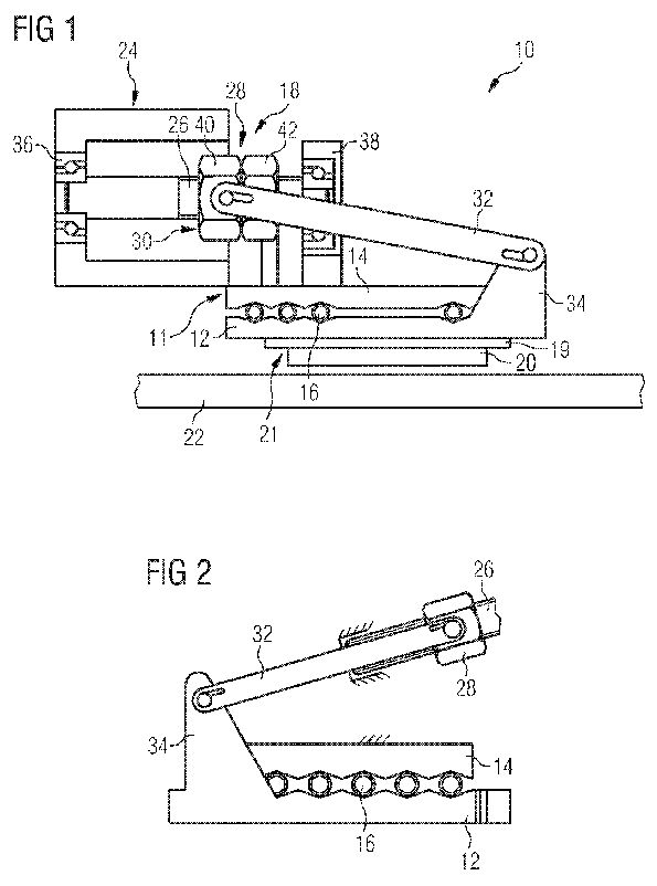
[0015] FIG. 1 shows sections of a first exemplary embodiment of an electromechanical brake 10 which are detailed here as a disk brake for a motor vehicle and which are of particular interest within the scope of the present invention. The brake 10 includes an integrated self-energizing system, as is known for instance from the already cited WO 02/095257, to which reference is made in detail. Such a self-energizing system has a wedge arrangement 11 with two wedge plates 12, 14, between which rollers 16 are arranged for friction reduction purposes. In order to actuate the vehicle brake 10, the one wedge plate 12 is moved relative to the other wedge plate 14 by means of an actuator 18, as a result of which the distance between the two wedge plates 12, 14 increases. The stroke thus occurring as standard in one direction in respect of the main planes of the two wedge plates 12, 14 is used to bring a friction member 21 consisting of a lining support plate 19 and a friction lining 20 affixed thereto into contact with a brake disk 22. If the brake disk 22 rotates, it exerts a drive force on the friction lining 20 by way of the frictional force occurring between the friction lining 20 and the brake disk 22, said drive force effecting an additional “spreading” i.e. a larger stroke of the wedge arrangement 11 and thus a corresponding increase in the force, with which the friction lining 20 is pressed against the brake disk 22, back to the wedge plates 12, 14, without the force generated by the actuator 18 itself needing to be increased for this purpose.
[0016] The actuator 18 includes a single electric motor 24, which may set a rotationally received, axially stationary spindle 26 to rotate. A nut 28 is arranged on the spindle 26 in a rotationally fixed fashion, said nut 28 being able to travel axially on the spindle by rotating said spindle 26. As an alternative, the nut can be received in a stationary and rotational fashion and the spindle can travel axially in a rotationally fixed fashion (not shown). The spindle 26 and the nut 28 together form a spindle/nut arrangement 30.
[0017] A coupling rod 32 is used to transmit the axial movement of the nut 28 effected by rotating the spindle 26 onto the wedge plate 12, said coupling rod 32 being pivotably coupled with its one end to the outside of the nut 28 and with its other end to an appendage 34 of the wedge plate 12.
[0018] The electric motor 24 of the actuator 18 is activated in order to actuate the brake 10 so as to set the spindle 26 to rotate in the one or the other direction. The desired rotational direction of the spindle 26 depends on the direction in which the brake disk 22 to be slowed down rotates. So that the self-energizing system is able to fulfill its function, the actuator 18 must move the wedge plate 12 in respect of the wedge plate 14 in the direction in which the brake disk 22 also rotates. It is only then that the rollers 16 between the two wedge plates 12 and 14 run to those wedge bevels, which, following contact of the friction lining 20 with the brake disk 22, effect a further spreading of the wedge arrangement 11 and thus the desired self-boost. The spindle 26 is rotated in the opposite direction in order to terminate the braking action, as a result of which the two wedge plates 12, 14 approach one another again and the friction lining 20 disengages from the brake disk 20.
[0019] For the reasons illustrated in the introduction (possible change between a traction wedge arrangement and a compressive wedge arrangement as a function of the frictional value prevailing between the friction lining and the brake), any backlash in the actuator 18 is unwanted. To avoid such backlash, the brake 10, in more precise terms the actuator 18 thereof, has a series of measures. The spindle 26 is thus rotationally received by means of two axially prestressed ball bearings 36, 38. In the exemplary embodiment shown, the two ball bearings 36, 38 are oblique ball bearings, which axially prestress the spindle 26, i.e. apply a force acting in the axial direction upon the spindle 26. The axial prestresses applied by the ball bearing 36 and/or 38 on the spindle 26 are aligned oppositely, so that any axial backlash in the spindle 26 is eliminated.
[0020] To eliminate backlash between the nut 28 and the spindle 26, the nut is attached to the spindle using axial prestress. In the exemplary embodiment shown, the nut 28 consists of two nut elements 40, 42, which are connected to one another by way of a screw thread (not shown) and can be moved axially towards and away from one another by means of screwing in the one and/or the other direction. The axial distance between the two nut elements 40, 42 can thus be adjusted. In order to eliminate backlash, the axial distance of the two nut elements 40, 42 is thus changed until there is no backlash still present in the spindle 26. The established position of the nut elements 40, 42 is fixed by means of a counter nut (not shown).
[0021] The coupling rod 32 can have backlash on its linking points. To eliminate such backlash, the linking and/or bearing points of the coupling rod 32 are prestressed in one direction, the available backlash can no longer have an effect.
[0022] The said measures ensure that each actuation movement of the actuator 18 is transmitted with zero backlash onto the wedge plate 12 of the self-energizing system. The control of the brake 10 thus proves to be considerably easier.
[0023] FIG. 2 shows a second exemplary embodiment of a brake 10, which only differs from the first exemplary embodiment illustrated in FIG. 1 in that the spindle 26 extends in parallel to that wedge bevel of the wedge arrangement 11, which is used to self-boost braking actions in the main braking direction. With one actuation of the brake 10 for braking in the main braking direction, no relative movement occurs between the moved wedge plate 12 and the nut 28 in the case of a spindle 26 which is arranged in parallel to the said wedge bevel. No shear forces are then also transmitted onto the spindle 26.
ELECTROMECHANICAL VEHICLE BRAKE COMPRISING A FRICTION LINING WEAR COMPENSATING DEVICE
WO2007057464
Wedge brake
SI1972822
Method for supplying electrical supply current to electronic wedge brake...
DE102009007796
Movable device e.g. motor vehicle stopping method...
DE102007061940
WEDGE BRAKE HAVING WEDGE ELEMENTS WHICH ARE MOVED IN OPPOSITE DIRECTIONS
WO2007051818
Wedge brake for a rotatable body.
EP0066134
http://www.siemens.com/innovation/en/publikationen/publications_pof/pof_fall_2005/auto_electronics/braking_systems.htm
Wonder
Wedge
by
Norbert Aschenbrenner
by
Norbert Aschenbrenner
A
revolution in braking technology is in the making. A new
electronic wedge brake currently being developed for market
launch by Siemens can be used for any type of vehicle. But
that’s not all. The new brake is also faster, less expensive
and more efficient than conventional hydraulic systems.
Bernd Gombert cranks up the metal disk until it rotates at speed. "Now, press here and make it stop," he says. It requires strong pressure applied with the palm of the hand before the plastic brake pad brings the disk gradually to a halt. "Friction," says Gombert in his dry engineer’s manner. "That’s how today’s cars brake. Now try the wedge." Once again, he cranks the disk up, only this time harder. The small wedge is mounted at the side, between a metal pin, which sits parallel to the disk, and a guide mechanism. Although the metal disk is rotating very quickly, a prod of the index finger is all it takes for the wedge to be literally dragged onto the disk, which snaps to a halt immediately. "That’s how they used to brake horse-drawn vehicles," says Gombert with a grin. "And, in principle, that’s how brakes will function in the future. A lowenergy, low-cost system with a simple mechanical design!" Not that Gombert is advocating a return to the horse-drawn era, when wedge brakes were used to provide a highly effective but very abrupt means of bringing the wheels of a cart or carriage to a halt. Instead, he’s referring to the Electronic Wedge Brake (EWB), a development project that Gombert heads at Siemens VDO Automotive (SV). "The difference is that we stop the wedge from completely locking the wheel by preventing it from being fully dragged in between the mounting and the brake disk," he explains. The trick here is to allow the wedge to be pulled in until the desired braking moment has been achieved, but no further. This in turn requires sophisticated sensors and a precisely controllable electric motor.
For each wheel, the electronic wedge brake has a control unit (see diagram above) consisting of a brake pad, a mechanical transfer system, two electric motors for precision control, and sensors to measure movements and forces. Around 100 times a second, a total of four sensors measure wheel rotation and therefore the speed of the vehicle, the forces on the brake and the position of the wedge. Whenever the driver presses the brake pedal, the system transmits the force electromechanically to the wheels, which are electronically networked with one another. Depending on the sensor readings and the braking signal coming from the driver, the two electric motors move the brake pad over a series of rollers along a slanted surface—the actual wedge. The position of the rollers on the inclined surface determines the pressure point of the brake pad. When the pad presses against the disk, the latter is immediately braked. As soon as a high braking moment is generated by increasingly powerful frictional forces, the electric motors either hold the brake pad in position or move it back over the roller bearing and into an optimum position. The distances involved are a matter of micrometers, and the response times are measured in milliseconds. The vehicle’s onboard 12-V network is perfectly suited to driving the electric motors. In fact, a flashlight battery would also be powerful enough.
"The intelligently controlled wedge converts the vehicle’s kinetic energy directly into braking energy," explains Gombert. As a result of this self-reinforcement, the EWB only requires one tenth of the actuating energy required by today’s hydraulic braking systems. What’s more, it also responds substantially quicker. Given this significantly enhanced efficiency, the EWB will also have smaller dimensions and therefore reduce total vehicle weight. At the same time, there will no longer be any need for brake lines, a power brake unit or a brake fluid reservoir, which will free up a volume of around 22 l in the engine compartment and thereby give vehicle designers added scope. "And you won’t need a hand brake any more," adds Karsten Hofmann, head of Chassis Product Marketing at SV.
Likewise, the well-nigh ubiquitous ABS anti-lock braking system and the less prevalent electronic stability program (ESP) will be replaced by the integrated software in the EWB system. "We’ve developed our own algorithm that reproduces these functions," explains Hofmann. "But our system is much quicker." All in all, it takes 140 to 170 ms for a conventional ABS to generate full braking power. The EWB only needs around 100nbsp;ms, an advantage which, according to Siemens engineers, should make a difference on uneven and icy roads. "Our system can control each individual wheel faster than any hydraulic system and thus keep them on course better," says Hofmann.
With the EWB project, Siemens VDO is also preparing for the time when electric vehicles will claim a much greater market share. In fact, successful hybrid cars can already be seen on our roads today, including the Toyota Prius, which enjoys cult status in California and has been voted Car of the Year 2005 by European auto magazines. Future electric cars may well be equipped with an individual motor for each wheel. This would generate substantially higher torque directly at the wheel and therefore liberate more power to accelerate the vehicle. Another possibility would be to recover kinetic energy during braking. Here, the electric motor fitted to the wheel would also function as a generator and produce electricity to recharge the battery.
Brake by wire. The EWB would be a perfect complement here, as it would be able to supply whatever additional and emergency braking capacity is required. It could also be used in conventionally powered vehicles to provide a range of electronic "brake-by-wire" features. These might include a "soft-stop" function, whereby the system brings the vehicle to a smooth halt by automatically reducing the braking force just before it stops, or an antistall assistant controlled by software, which would prevent the vehicle from rolling back when pulling away on a gradient. Such a feature would certainly be welcomed by student drivers. Although the EWB requires a constant electrical current, it is immune to problems associated with the onboard power supply. "If the current to one of the wheels were disrupted, the system would automatically compensate by distributing the braking power to the others," says Hofmann. And if the vehicle’s entire power supply system failed, an emergency battery would ensure that all vital functions were maintained until the fault was remedied.
However, Gombert isn’t too worried about problems related to the new system. He’s much more interested in its potential. Gombert was a top researcher at the German Aerospace Center (DLR) before leaving to devote more time to the EWB project. In 2000 he set up his own company, eStop, which was taken over by Siemens VDO in 2005. Gombert holds almost 120 patents, 40 of them with eStop, for various aspects of the EWB system. In September of this year, his team demonstrated the principle at the International Motor Show in Frankfurt, Germany, and are currently testing the system in a vehicle that will be made available to automakers at the end of the year for further tests. The pilot customer is a major European automobile manufacturer. If everything goes according to plan, the first vehicles fitted with the EWB as standard should hit the roads in 2009. Before then, however, this completely new technology will have to prove that it can compete both technically and economically with a braking system that has been successfully employed for more than 70 years. Aside from passenger cars, Gombert also sees big potential for the new system in heavy-duty vehicles. Today’s trucks are fitted with air brakes, and it can take up to a second for the brake signal to reach a rear trailer. Using the EWB system, it would be possible to brake a trailer more quickly and in a more controlled way. In principle, any wheeled vehicle can be braked using this new system, including high-speed trains, which are currently equipped with maintenance-intensive and therefore expensive brakes. Gombert also has an eye on automation technology, which employs all sorts of motors. His vision is that his technology might one day be used to brake and regulate anything driven by a motor.
ELECTROMECHANICAL
ZERO BACKLASH BRAKE
WO2007057465
US2009101453
WO2007057465
US2009101453
Inventor: BAIER-WELT CHRISTIAN et al
The invention relates to an electromechanical brake (10), especially for vehicles, which comprises an electrical actuator (18) producing an actuation force and acting upon at least one friction member (21) in order to force said member against a component (21) of the brake to be slowed down, thereby eliciting a frictional force. The invention also comprises a self-energizing system arranged between the friction member (21) and the electrical actuator (18). Said system comprises a wedge arrangement (11) that serves to self-boost the actuation force produced by the electrical actuator (18). The aim of the invention is to simplify said system in terms of design and control technology. For this purpose, the actuator (18) has a single electric motor (24) and the actuation force produced by it is released via a spindle/nut arrangement (30) having a rotationally received, stationary spindle (26) and a rotationally fixed nut (28) that can axially travel on the spindle by rotating the spindle. Alternatively, the nut is received so as to be stationary and rotatable and the spindle is rotationally fixed and can axially travel. The spindle (26) is rotationally received by means of axially prestressed bearings (36, 38) and the nut (28) is mounted on the spindle (26) in a manner axially prestressed in relation to the spindle. The traveling movement of the nut (28) is transmitted onto the wedge arrangement (11) by means of a transmission element which is connected to the nut (28) and to the wedge arrangement (11) with zero backlash.
[0001] The invention relates to an electromechanical brake, especially for vehicles, which comprises an electrical actuator producing an actuation force and acting upon at least one friction member in order to force said member against a component of the brake to be slowed down, thereby eliciting a frictional force and a self-energizing system arranged between the friction member and the electrical actuator and comprising a wedge arrangement that serves to self-boost the actuation force produced by the electrical actuator. The wedge arrangement has at least one wedge with a gradient angle a, which is supported against an associated support. Such an electromechanical brake is known from WO 02/095257.
[0002] Another electromechanical brake with a self-energizing system is known from the German patent specification DE 198 19 564 C2. In the case of the brake described in this document, the problem arises that the extent of self-boosting, determined by the selection of the gradient angle a of the wedge or wedges of the wedge arrangement, can always only be dimensioned so large that irrespective of the friction coefficient p between the friction lining and the component to be slowed down, which changes depending on the operating state of the brake, either a compressive force or a tractive force is always exerted on the wedge of the self-energizing system. A change of sign of the actuator force is to be avoided, because otherwise the backlash existing in the actuator has to be passed through, which results in undefined states and thus in unwanted fluctuations in the control parameters (braking force). As a result of these restrictions, with the electromechanical brake known from the said document, the range of the optimum self-boost, namely the range in which the value of the friction coefficient u corresponds at least approximately to the value tan a, cannot be used, because the required actuation force, in other words the actuator force, changes its direction at the point of optimum self-boost, i.e. if the friction coefficient µ has the same value as the tangent of the gradient angle a.
[0003] In accordance with the aforementioned WO 02/095257, the problem of the actuator backlash is solved by means of an actuator, which has two electric motors, which operate against one another in a defined manner in order to eliminate actuator backlash which exists in most operating situations. Such a solution apparently defines an increased outlay in terms of design and control technology.
[0004] The object underlying the invention is to provide an improved electromechanical brake with self-boost, the working range of which can lie within the range of the optimum self-boost without resulting in negative effects in respect of its controllability and which is still configured in a simple fashion in terms of design and can be easily handled in terms of control technology.
[0005] Based on an electromechanical brake of the type mentioned in the introduction, this object is achieved in accordance with the invention by a brake having the features specified in claim 1 or 2. To simplify the design and control technology outlay, the actuator of the inventive brake accordingly has only one single electric motor, which releases the actuation force produced thereby via a spindle/nut arrangement either having a rotationally received, stationary spindle and a rotational fixed nut that can axially travel on the spindle by rotating the spindle or a rotationally received, stationary nut and a rotationally fixed spindle that can axially travel by rotating the nut. The rotational spindle is rotationally received by means of one or several axially prestressed bearings so that no unwanted backlash occurs in the actuator. The axial prestress of receiving the spindle eliminates any axial spindle backlash. The nut is also attached prestressed to the spindle in the axial direction in relation to the spindle in order to eliminate any backlash between the nut and the spindle. Finally, the traveling movement of the nut or of the spindle is transmitted onto the wedge arrangement by means of a transmission element which is connected on the one hand to the nut or the spindle and on the other hand to the wedge arrangement with zero backlash. In this way, each actuation movement produced by the electric motor of the actuator is transmitted with zero backlash onto the wedge arrangement of the self-energizing system, irrespective of whether the momentary operating state of the brake requires the exertion of a compressive force or a tractive force onto the wedge arrangement in order to maintain a desired brake force.
[0006] In accordance with a preferred embodiment of the electromechanical brake according to the invention, at least one axially prestressed oblique ball bearing receives the rotational spindle in a prestressed fashion in the axial direction. The oblique ball bearing is arranged in a known manner to persons skilled in the art within this field such that it exerts a certain amount of pressure in the axial direction and thus eliminates potentially existing axial backlash of the spindle received therewith. Advantageously in terms of design, two axially prestressed oblique ball bearings are used to rotationally receive the spindle with zero backlash, with the axial prestress of these two bearings then taking place in opposite directions in respect of this spindle. All other bearings enabling an axial prestress such as e.g. roller or needle bearings can likewise be used. Alternatively, the rotational spindle is received in a fixed/moveable bearing arrangement.
[0007] With preferred exemplary embodiments of the inventive electromechanical brake, the axial prestressing of the nut in respect of the spindle is realized here in that the nut includes two nut elements which are axially prestressed in respect of each other. The two nut elements have an adjustable and fixable axial distance from one another. The axial distance of the two nut elements is adjusted such that backlash no longer exists in respect of the spindle and this axial distance is then fixed in order to eliminate any backlash between the nut and the spindle. For instance, the two nut elements can be connected to one another by way of an axial thread, so that the axial distance between both nut elements can be adjusted and fixed by means of a counter nut by means of screwing the one nut element into and out of the other nut element.
[0008] With a preferred embodiment of the inventive electromechanical brake, the transmission element is a coupling bar which is pivotably coupled to the nut or the spindle and the wedge arrangement, the bearing points of which are prestressed with zero backlash. According to one embodiment, the bearing points are embodied as a polygonal profile so that a zero backlash position is achieved by means of rotation which is carried out relative to one another. The bearing points can also be embodied as solid body links, e.g. in the shape of a leaf spring. Alternatively, each other transmission element can be used, which is either with zero backlash or can be configured with zero backlash by suitably embodying its linkage points and/or bearing points. For instance, a two-piece rod which is pivotably coupled to the nut or spindle and the wedge arrangement can be used as a transmission element, the two parts of which are connected to one another by means of a thread engagement. By screwing the one part into and/or out of the other respectively, the length of such a rod can be adjusted such that backlash present on the linking and/or bearing points no longer has an effect.
[0009] With preferred embodiments of the inventive electromechanical brake, the spindle extends in parallel or in any case almost parallel to a wedge bevel of the wedge arrangement. The wedge bevel is preferably that which is used for braking in the direction in which the most braking processes are expected. In the case of a brake for a motor vehicle, this wedge bevel will be the wedge bevel responsible for braking while traveling forward. The spindle arranged at least essentially parallel to the wedge bevel provides for hardly any and/or no relative movement to still occur between the nut or the spindle of the spindle/nut arrangement and the component of the wedge arrangement moved by the actuator, if this is such a brake in which the wedge bevel of the wedge arrangement which is parallel to the spindle is used. The spindle which is arranged at least essentially parallel to the wedge bevel, which corresponds to the main braking direction, is also characterized in the case of braking actions in the main braking direction by the extensive or complete absence of shear forces, which would otherwise, i.e. in the event of an arrangement of the spindle selected at least essentially parallel to the wedge bevel, act upon the spindle.
[0010] With applications of the inventive electromechanical brake, in which the gear reduction of the rotary motion of the electric motor which is achieved by the spindle/nut arrangement is not sufficient, the electric motor can itself be embodied as a engine/transmission unit in order to provide a larger overall gear reduction.
[0011] On the whole, provision is made in accordance with the invention, as a result of only one spindle/nut arrangement and only one electric motor, for a more cost-effective electromechanical brake which is easier to control in terms of control technology and is of a simpler design.
[0012] Two exemplary embodiments of an inventive electromechanical brake are described in more detail below with reference to the appended schematic figures, in which;
[0013] FIG. 1 shows a partially cutout view of the most important components of a first exemplary embodiment of an inventive electromechanical brake having a self-energizing system, and
[0014] FIG. 2 shows a detailed view of a second exemplary embodiment of an inventive electromechanical brake having a self-energizing system which is modified by comparison with FIG. 1.
[0015] FIG. 1 shows sections of a first exemplary embodiment of an electromechanical brake 10 which are detailed here as a disk brake for a motor vehicle and which are of particular interest within the scope of the present invention. The brake 10 includes an integrated self-energizing system, as is known for instance from the already cited WO 02/095257, to which reference is made in detail. Such a self-energizing system has a wedge arrangement 11 with two wedge plates 12, 14, between which rollers 16 are arranged for friction reduction purposes. In order to actuate the vehicle brake 10, the one wedge plate 12 is moved relative to the other wedge plate 14 by means of an actuator 18, as a result of which the distance between the two wedge plates 12, 14 increases. The stroke thus occurring as standard in one direction in respect of the main planes of the two wedge plates 12, 14 is used to bring a friction member 21 consisting of a lining support plate 19 and a friction lining 20 affixed thereto into contact with a brake disk 22. If the brake disk 22 rotates, it exerts a drive force on the friction lining 20 by way of the frictional force occurring between the friction lining 20 and the brake disk 22, said drive force effecting an additional “spreading” i.e. a larger stroke of the wedge arrangement 11 and thus a corresponding increase in the force, with which the friction lining 20 is pressed against the brake disk 22, back to the wedge plates 12, 14, without the force generated by the actuator 18 itself needing to be increased for this purpose.
[0016] The actuator 18 includes a single electric motor 24, which may set a rotationally received, axially stationary spindle 26 to rotate. A nut 28 is arranged on the spindle 26 in a rotationally fixed fashion, said nut 28 being able to travel axially on the spindle by rotating said spindle 26. As an alternative, the nut can be received in a stationary and rotational fashion and the spindle can travel axially in a rotationally fixed fashion (not shown). The spindle 26 and the nut 28 together form a spindle/nut arrangement 30.
[0017] A coupling rod 32 is used to transmit the axial movement of the nut 28 effected by rotating the spindle 26 onto the wedge plate 12, said coupling rod 32 being pivotably coupled with its one end to the outside of the nut 28 and with its other end to an appendage 34 of the wedge plate 12.
[0018] The electric motor 24 of the actuator 18 is activated in order to actuate the brake 10 so as to set the spindle 26 to rotate in the one or the other direction. The desired rotational direction of the spindle 26 depends on the direction in which the brake disk 22 to be slowed down rotates. So that the self-energizing system is able to fulfill its function, the actuator 18 must move the wedge plate 12 in respect of the wedge plate 14 in the direction in which the brake disk 22 also rotates. It is only then that the rollers 16 between the two wedge plates 12 and 14 run to those wedge bevels, which, following contact of the friction lining 20 with the brake disk 22, effect a further spreading of the wedge arrangement 11 and thus the desired self-boost. The spindle 26 is rotated in the opposite direction in order to terminate the braking action, as a result of which the two wedge plates 12, 14 approach one another again and the friction lining 20 disengages from the brake disk 20.
[0019] For the reasons illustrated in the introduction (possible change between a traction wedge arrangement and a compressive wedge arrangement as a function of the frictional value prevailing between the friction lining and the brake), any backlash in the actuator 18 is unwanted. To avoid such backlash, the brake 10, in more precise terms the actuator 18 thereof, has a series of measures. The spindle 26 is thus rotationally received by means of two axially prestressed ball bearings 36, 38. In the exemplary embodiment shown, the two ball bearings 36, 38 are oblique ball bearings, which axially prestress the spindle 26, i.e. apply a force acting in the axial direction upon the spindle 26. The axial prestresses applied by the ball bearing 36 and/or 38 on the spindle 26 are aligned oppositely, so that any axial backlash in the spindle 26 is eliminated.
[0020] To eliminate backlash between the nut 28 and the spindle 26, the nut is attached to the spindle using axial prestress. In the exemplary embodiment shown, the nut 28 consists of two nut elements 40, 42, which are connected to one another by way of a screw thread (not shown) and can be moved axially towards and away from one another by means of screwing in the one and/or the other direction. The axial distance between the two nut elements 40, 42 can thus be adjusted. In order to eliminate backlash, the axial distance of the two nut elements 40, 42 is thus changed until there is no backlash still present in the spindle 26. The established position of the nut elements 40, 42 is fixed by means of a counter nut (not shown).
[0021] The coupling rod 32 can have backlash on its linking points. To eliminate such backlash, the linking and/or bearing points of the coupling rod 32 are prestressed in one direction, the available backlash can no longer have an effect.
[0022] The said measures ensure that each actuation movement of the actuator 18 is transmitted with zero backlash onto the wedge plate 12 of the self-energizing system. The control of the brake 10 thus proves to be considerably easier.
[0023] FIG. 2 shows a second exemplary embodiment of a brake 10, which only differs from the first exemplary embodiment illustrated in FIG. 1 in that the spindle 26 extends in parallel to that wedge bevel of the wedge arrangement 11, which is used to self-boost braking actions in the main braking direction. With one actuation of the brake 10 for braking in the main braking direction, no relative movement occurs between the moved wedge plate 12 and the nut 28 in the case of a spindle 26 which is arranged in parallel to the said wedge bevel. No shear forces are then also transmitted onto the spindle 26.
Related
PatentsAssigned to Siemens
ELECTROMECHANICAL VEHICLE BRAKE COMPRISING A FRICTION LINING WEAR COMPENSATING DEVICE
WO2007057464
Wedge brake
SI1972822
Method for supplying electrical supply current to electronic wedge brake...
DE102009007796
Movable device e.g. motor vehicle stopping method...
DE102007061940
WEDGE BRAKE HAVING WEDGE ELEMENTS WHICH ARE MOVED IN OPPOSITE DIRECTIONS
WO2007051818
Wedge brake for a rotatable body.
EP0066134