rexresearch
Maxwell WHISSON
Air Well
Max-Air
http://www.waterunlimited.com.au/
General
Enquires can be fowarded to WATER UNLIMITED.
Postal: PO Box 695
West Perth WA 6872
Australia
Em Telephone: +61 8 9381 2177
Fax +61 8 9486 4944
Introducing
the Max Water
Water
UN Limited was incorporated to acquire the technology and
intellectual property associated with water from ambient air
technology, also known as ‘the Max Water', from world renowned
Perth based inventor Dr Max Whisson.
This
breakthrough technology has the potential to produce water
from air using a turbine containing refrigerants. If
successful, this technology will be capable of supplying
commercial quantities of water for a wide variety of uses
powered by wind energy alone.
If
successful the technology developed by Dr Max Whisson may
represent the most important breakthrough in water production
in recent years. The commercialisation of Max Water may be by
license, direct sales, distributor networks or a combination
of these. Under any marketing strategy a percentage of units
produced will be donated via appropriate charitable
organizations to supply water to areas of extreme poverty in
developing economies.
Our
company mission is to now build the first complete prototype
and hopefully prove the concept.
Video
: http://www.waterunlimited.com.au/video.html
Learn
more about the Max Water : This short presentation
outlines how the Max Water may use only wind power to cool the
air and achieve condensation of the contained water. It
contains drawings, research and other relevant statistical
information. DOWNLOAD PDF (2.8 MB):
http://www.waterunlimited.com.au/images/presentation/WaterUNlimited-MAY.pdf
QuickTime
Movie :
http://www.waterunlimited.com.au/images/presentation/WaterUNlimited-MAY-big.mov
YouTube
:
http://www.youtube.com/watch?v=Gf0krn99Y20
http://www.abc.net.au/science/news/stories/2007/1860729.htm
ABC
Science Online
( Friday,
2 March 2007 )
Making Water Out of Thin Air
Anna Salleh
Could a
wind turbine that sucks water out of the air supply enough
water for the whole world?
A
wind-driven device could provide an unlimited water supply by
harvesting water from the air, says its Australian inventor.
But
critics are asking if it's too good to be true.
Dr Max
Whisson, a retired medical specialist turned inventor, says he
has designed a highly efficient wind turbine that can run a
refrigeration system to cool air and condense moisture from
it.
"The
wind carries in the water and [provides] the power required to
separate that water from the wind," says Whisson, who is based
in Perth.
He says
there is a huge amount of water in the atmosphere that is
replaced every few hours. This means the whole world could
just use water from the air without disrupting the
environment.
Whisson
says the system would even harvest significant amounts of
water in areas with low humidity.
He says
a 4 metre square device could extract an average 7500 litres
of water a day.
In his
design, moisture-laden air enters the system and is cooled by
a drop in pressure behind the wind turbine blades, says
Whisson.
The air
then flows into a chamber containing refrigerated metal plates
covered by a non-wettable surface that causes water droplets
to run off immediately into a collection point.
Could
it work?
Full
technical details of the design are not available but at least
one mechanical engineer is sceptical.
"I have
found in general that inventors tend to enormously overstate
the capacities of their devices. They just have a very rosy
outlook on what their devices will do," says mechanical
engineer Professor John Reizes, an adjunct professor at the
University of New South Wales.
"It's
not until you've made one that you discover all the problems."
Reizes,
who specialises in heat transfer, says he is sceptical because
of the huge amount of energy that is needed to condense water.
Whisson
says he is well aware that a large amount of energy is
required to do the job.
"It's
like boiling a kettle in reverse," he says.
But he
is confident his wind turbine, still subject to patent
applications and yet to be independently tested, is efficient
enough.
"The
wind turbine is a surprisingly good development. I'm surprised
because it performs so well," says Whisson.
And he
says the power generating part of the wind turbine can simply
be increased to collect the wind power required for the
condensation process.
"We've
got unlimited power," he says.
But
Reizes says wind turbines are so far only about 30% efficient
at best and the energy arriving at them is very diffuse,
requiring large devices to collect the energy.
"It may
be a fantastic idea on paper and it looks as if it could
work," he says.
"However,
the thing may have to be so big to drive this device that it
becomes impractical."
Drawing
moisture from air
One
thing seems more certain. If the system does work, it is
unlikely to backfire on the environment, says Dr Michael
Coughlan, of Australia's Bureau of Meteorology.
He says
the amount of water that humans would use is trivial compared
with the amount available in the atmosphere.
"If you
can tap into it, then go for it, because you would do little
to upset the hydrological cycle," says Coughlan.
http://www.alternate-energy-sources.com/Whisson-windmill.html
The Whisson Windmill - Water From Air, Why
Not?
...Dr
Whisson himself describes his Whisson Windmill as follows:
"The essential principle is that more wind is used for power
than for water supply. In other words, the area of power
turbines is greater than the area of turbines leading to water
harvest. This is all made much easier by the invention of a
new kind of wind turbine or 'windmill'. The amount of water
available in the air is for all forseeable practical purposes
unlimited. The bottom 1 kilometre (in the atmosphere) alone
contains about 1.000,000,000,000,000 litres of water and that
is turned over every few hours. The "Whisson Windmill" or Max
Water From Air device will make it possible to get adequate
water anywhere at any time, drought or no drought."
http://www.abc.net.au/austory/specials/windmills/default.htm
Windmills of Your Mind
PROGRAM
TRANSCRIPT: Monday, 21 May , 2007
JAMES O'LOUGHLIN:
Hello, I'm James O'Loughlin from "The New Inventors".
Australia has a long tradition of innovation, from the Hills
Hoist to the black box flight recorder, and our home grown
ideas have often found international markets.
Well, Perth inventor Max Whisson believes he may have come
up with a solution to the world's water problems and he has
some influential supporters. This is Max Whisson's story.
MAX WHISSON: The
state of the world at the moment is, I think, the most
dangerous in the evolution of Homo sapiens, for two main
reasons. Power is almost entirely in the hands of those who
gained power by exercising commercial advantage, and at the
same time the ability of modern technology to destroy the
world is unprecedented. The destruction of vast ecosystems
is happening as we speak: forests being destroyed, catchment
areas being destroyed, rivers being destroyed. We are a
highly developed species, can fly to the moon and do all
sorts of clever things, and we destroy the rivers all over
the planet. I think it’s utterly absurd, outrageous.
Grassroots action is the only hope to get a healthy world
community.
PROFESSOR ROGER
DAWKINS, SCIENCE CENTRE DIRECTOR: I know that some people
think that Max is a crackpot but he’s a very engaging one
and he’s certainly a very productive one.
MARCUS WHISSON,
SON: He can be a bit of a handful, he’s an eccentric old
bugger, he’d probably say that himself.
PHILLIP ADAMS,
FRIEND: I think Max is a reincarnation of an ancient Roman,
the Romans were wonderful at water.
MAX WHISSON: It
took me a little while to realise that the expanding
population of the world cannot rely on surface water which
accumulates from rain. We have to find unlimited sources of
water and the sea seemed to me to be the obvious source of
vast quantities of water. Seventy-one per cent of the
Earth’s surface at an average depth of four or five
kilometres, and I thought, how can you purify that water
without fossil fuels or big machines or high technology? And
sunlight seemed to be the obvious way. I came up with the
idea of the Water Road in about 2002 in a sort of Eureka
moment. Most places in need of water are far inland and it
would seem so logical to just run the sea water inland over
a long distance, producing pure water as it goes. The Water
Road is a very simple design. It’s just a series of parallel
black pipes, preferably to a width of about 10 metres,
covered in a transparent cover such as perspex or
polycarbonate, and maybe a thousand kilometres long. The sea
water heats to 70 or 80 degrees, by my calculation, in about
three to four days, heated by the sun, and at intervals the
sea water is run into big swimming pools that I call
evaporation ponds. The hot, wet air in the evaporation ponds
is ducted up to a hilltop where it just condenses in a
special condensation shed. So you’ve got pure water produced
at a high point and that greatly assists the distribution to
irrigation or to households along the way. A pipeline of
that size would produce about 200,000 litres per kilometre
per day. The salt from the returning sea water goes back to
the sea where it’s diluted within minutes to normal sea
water. But it could be sent to a salt manufacturer.
COLIN BARBOUTIS,
BUSINESS PARTNER: When Max first mentioned the Water Road to
me, I thought, this could be an answer for the water problem
that we’re going to have in Perth in the very near future.
Max’s mind works very differently to most people. And Max
told me this himself, he said, “Colin all my life, I’ve seen
things differently to most people.” He said, “You see a
glass of water on the table, I see a mathematical
calculation for a vessel that holds liquid.”
ANNEMARIE WHISSON,
WIFE: When he comes to invention he’s very, very obsessive
and quite stubborn, but in a good way.
MAX WHISSON: I
graduated as a doctor in '55. I met Annemarie whilst I was
working on cancer research in London.
ANNEMARIE WHISSON:
I trained as a medical technologist in Switzerland and I was
his research assistant. Oh goodness me, after two weeks, I
just fell in love with this man and, and after a while, you
know, I could see, he said he liked me too and so we had a
little bit lunch together or coffee and, you know from then
on it started, you know, I was just completely besotted with
him.
MAX WHISSON:
Annemarie and I have two sons and there are four sons from
my first marriage.
ALEX WHISSON, SON:
I think in many ways my mum’s sacrificed her own life to
support my dad’s inventions and his scientific research
work. If it wasn’t for my mum, my dad would be a
disorganised brain in the ether somewhere. I mean she
actually roots him in the earth, she actually grounds him in
reality and he’d be completely lost without her.
MARCUS WHISSON,
SON: He is an eccentric, the quintessential nutty professor.
For a long time I know in the 1980s he had a fairly healthy
obsession with solar power from cooling someone’s head with
a solar-powered hat to allowing a bicycle to be used not by
pedal power but by solar power.
MAX WHISSON: I
worked for many years as a haematologist at the Red Cross
Blood Bank in Western Australia.
PHILLIP ADAMS,
FRIEND: By the late '80s the magnitude of the AIDS epidemic
was becoming well known and I was concerned about my
daughter, the doctor, getting needle stick injuries where
she was working in an ER hospital in New York. And I was
expressing these concerns to Max, who miraculously was
working on a retractable needle.
To any project he
examines Max brings a very fresh intelligence and so he
looked at the needle again and again and he then came up
with a Mark II, a completely different way of solving the
issue involving a sleeve rather than a retreating needle.
PROFESSOR ROGER
DAWKINS, SCIENCE CENTRE DIRECTOR: It was 1982 in the early
days of HIV that I really got to know Max Whisson. He does
have some weird and wonderful ideas, there’s no doubt about
it.
The Needlesleeve
seems to be a very good idea and it seems to work very well.
I’d like to see it in use.
Max has always
been very limited by funds. The country really needs to
support people like Max without pressing them to early
commercialisation because there are hazards in early
commercialisation and many a good project has really been
destroyed by the commercial partners.
ALEX WHISSON, SON:
There was a very nasty and prolonged court case involving my
dad’s Needlesleeve invention which basically involved some
of his former business associates laying claim to his
inventions. And even though he won that case actually on
three separate occasions, it has left him a bit bitter.
PHILLIP ADAMS,
FRIEND: The saddest thing for Max is that his needle, his
wonderful hypodermic that prevents needlestick injury, isn’t
being manufactured to this day because of the problems he’s
had in an out of courts. Great shame.
ANNEMARIE WHISSON,
WIFE: I think Max is actually a renaissance man. He’s so
interested in so many things. He’s interested in physics,
biology, cancer, politics nature, birds. He loves reading
poetry and he writes poetry himself and short stories. He
plays the violin in the Fremantle Symphony Orchestra. He
enjoys it immensely. Even when he’s very, very tired he
always goes to rehearsal.
MAX WHISSON: For
the last nine years Annemarie and I have lived in separate
places. I think at a certain stage of life there is some
sense in having a wife down the road. There were quite a lot
of conflicts.
ALEX WHISSON, SON:
My dad was always a workaholic and he’d often go on extended
trips to haematology conferences, medical conferences, and
never invite my mother on those trips. She felt excluded, I
think, from more and more aspects of his life. And as well,
truth be told, he had a wandering eye for other women. My
dad’s inventions have cost a fortune in patents and that’s
led to financial difficulties for the family, which has been
tough, especially on my mum.
MARCUS WHISSON,
SON: It has taken enormous emotional toll and it can be up
and down with my parents’ relationship, but at the end of
the day they’re most in love and really support one another.
ANNEMARIE WHISSON,
WIFE: We see each other every day. He actually has got less
difficult now. I think it makes all sense now in hindsight.
’94, ’95 he started to get sometimes quite aggressive,
verbally, and short-tempered and then it developed even in a
kind of paranoia as well. I was really very puzzled about it
and I thought, what is going on? And sometimes you know he
accused us of things which was completely irrational which
he never had done before. And Marcus just said, “I think dad
is going senile.”
ALEX WHISSON, SON:
Strange things started happening with my dad’s brain. He’d
be able to read the start of a paragraph but not the end of
it. He couldn’t distinguish left from right, he’d get lost
driving from Subiaco to Nedlands on a route that he’d
travelled a thousand times before.
ANNEMARIE WHISSON,
WIFE: And then again we said, “Please go to the doctor. We
can’t do anything.” And he said very aggressively, “I don’t
need your advice.”
MARCUS WHISSON,
SON: It was August the 17th 2000, the day after my mother’s
birthday. It was a blessing in disguise for him. My father
was involved in an accident where he hit a parked ute and he
was given a scan and they found a tumour the size of my
fist, a huge tumour in the back of his head, pressing
against his visual cortex.
ALEX WHISSON, SON:
And suddenly it was like a revelation for all of us because
we all realised sort of what had been happening with his
brain over these past few years.
MARCUS WHISSON,
SON: It was a benign tumour but they realised that they had
to operate immediately because there was every chance that
it would break through his skull.
MAX WHISSON: An
incredibly, I tell you, extraordinarily skilful set of
surgeons, got this whole thing out intact. And my whole
brain kind of went, "Ah, now I can work again." It was quite
amazing.
ALEX WHISSON, SON:
The amount of energy my dad has is phenomenal. He’s 76 now,
he still works probably 12, 14 hours a day. I have
tremendous admiration for my dad’s inventions. It’s never
just something trivial. It's the fact that they’re
inventions that are all geared towards actually improving
human welfare, improving the standards of life, the
conditions of life. It’s never something like, I don’t know,
a faster car or something that is just economically viable.
MAX WHISSON: I
suppose it’s occurred to me a little bit that I haven’t got
much time to do all the things that I really want to do. Do
I feel like an old man in a hurry? Yeah. My grandfather was
an irrigation controller in the little town of Dingee, just
not far from Bendigo in Victoria. So that I suppose gave me
an interest in water.
(Outdoors, standing near a dried up lake)
This was quite a lovely lake, a little lake, and I used to
visit it quite a lot, lots of birds came here, walk around
and see these beautiful things. It’s really tragic to see it
like this. You can’t look at this without being dreadfully
upset, especially knowing that it’s not just a one off and
it’s not really accidental. It’s because we’ve not taken
care of these things. The water table has gone down so that
the lake is worse because of that because everyone’s sucking
up water to keep their lawns healthy. The bores have gone
down deeper in Perth as in almost every city in the world.
I don’t really
know where I get my ideas but I do read widely in scientific
books and in things like "New Scientist". I do look very
carefully at what has gone before. I’m not an expert on
anything, but I throw things around and I sometimes kind of
turn ideas upside down and you suddenly find you’ve got a
really interesting answer that’s been staring people in the
face for centuries, you know? After working on the Water
Road for some time, I did some calculations which showed
that there’s heaps of water in the air. And so I began to
think, why bother with the sea water? So why not just
collect water from the air and you can collect the water
anywhere, in any small community or out in the desert or on
the coast, wherever you want.
PHILLIP ADAMS,
FRIEND: The water that’s in the air goes up for about a
hundred miles, constantly replenished by evaporation from
the ocean. Water is constantly extracted from the air in the
form of dew. The technology of extracting it is known. The
American army, for example, uses great thundering diesel
machines to pull it out of the air, but that’s not very
appropriate technology for a world suffering climate change.
Max thinks, no, no, no, I can use the air to produce the
power to produce the water.
MAX WHISSON: The
key to the process is to refrigerate the air as quickly as
possible so that water separates from the air and condenses
as drops which will run down into a collection tank.
The best place to
remove heat quickly is as the air hits a windmill. Now
existing windmills did not work out at all well so I
invented a new one and I’ve arranged to have it refrigerated
so that as soon as the wind hits that windmill it gets
cooled.
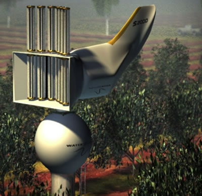
PHILLIP ADAMS,
FRIEND: The astonishing thing is if you even breathe near
one of Max’s windmills, the windmill starts spinning
furiously. And the theory is, the more air you can pass
through that windmill, the more air is available for cooling
and for dispensing the water within it. So it’s a very
elegant, very simple but tricky idea.
MAX WHISSON: There
was a point where I had a bit of a hitch. I could achieve
fairly rapid condensation of water on a cold plate but it
would just stick as little droplets and not run off the
plate quickly so that water could be collected. And then I
came across this little chap, the little beetle called
Stenocara. It’s quite amazing how creatures over millions of
years evolve clever techniques which are ahead of us.
COLIN BARBOUTIS,
BUSINESS PARTNER: I was at Max’s house one day, and Max
said, "Well, if I tell you, you’re going to think I’m
completely mad." And we had the discussion about the little
African beetle that pops out of the sand in the early
morning, does a headstand, faces his tummy into the breeze,
sits there most of the day and a little droplet of water
collects on the fibres on his tummy, runs down his nose and
into his mouth and he’s back into his burrow. So, he’s self
sufficient in water. And he said, “See, I told you you’d
think I was mad.” And I said, “Well I actually don’t know
that you’re mad, tell me a little bit more.” And he went
into more detail about how he’d been thinking about this for
a little while and that it was do-able. He said, "Often the
simplest things in this world are the hardest to invent."
MAX WHISSON:
Observing nature has taught me a lot. Now I have a surface
on the plates which is very like the surface on this little
beetle, the water touches the plates and just runs quickly
off. And so the little beetle has helped a great deal and
I’d like to thank him.
COLIN BARBOUTIS,
BUSINESS PARTNER: I believe it will take us another 12
months to fully develop this unit, to test it, to see if the
working prototypes do work. I guess Max is a bit of a
crackpot but then again, you'd have to be to come up with
some of these wonderful inventions. I’ve put my money on
that one out there. I think this water project is something
that's very unique. I absolutely believe in Max’s abilities
and have blind faith that he can do this and he'll get it
right. I may be wrong but that’s my thought.
PHILLIP ADAMS,
FRIEND: I’m a great enthusiast for the theory of the
windmill, and I write a newspaper column about my old
friend’s bright new idea. And in all my born days in over 50
years of writing columns, rarely seen a response like it - a
couple of thousand, a couple of thousand rapturous emails,
some sceptical, but mostly thrilled to the back teeth, from
every nook and cranny on the planet. From the Middle East,
from Venezuela, from Russia, from India, everyone thinks
this is it.
SEAN BLOCKSIDGE,
WINE COMPANY MANAGER: Sustainable farming’s something that
we’re looking at more and more. It’s an imperative,
particularly as a wine business. Certainly we do have some
fairly good, consistent rainfall but we’re certainly seeing
decreases. We’ve looked at the more traditional sources of
water in the past. One thing Margaret River doesn’t have a
shortage of is wind and certainly Max Whisson’s invention is
something worth investigating. We’re also regenerating large
tracts of land around the estate and we don’t necessarily
have the capacity to irrigate re-vegetation projects, so to
be able to put one of these windmills out there and have it
producing water would be fantastic.
PHILLIP ADAMS,
FRIEND: I’ve got a feeling there are many Max Whissons
around. At the moment of course he’s tilting at his
windmills, a bit like Don Quixote, because governments are
remarkably uninterested, but everyone else is.
MAX WHISSON: The
question whether the Water Road idea is now redundant
because of the Water Windmill is one that several people
have asked. I see the Water Road as a much more practical
national or large-scale water producing system.
PHILLIP ADAMS,
FRIEND: And provided Max can live another 10 years and work
out a few little minor details, it’s going to be fantastic.
A freeway, not just a Water Road, a freeway of fresh water -
wouldn’t that be fantastic? And Max wouldn’t even want to
charge toll, so it would be a freeway not a tollway.
ANNEMARIE WHISSON,
WIFE: I think I would quite like to live with Max again and
I think he probably would like to live with me. I still love
him. It’s just, it’s a different love, after, my goodness,
forty years. You know, we were incredibly passionately in
love but it’s, it has become a very comfortable love.
MAX WHISSON:
Certainly I feel bad that I haven’t provided a secure life.
I suppose, yeah, I probably haven’t been a perfect husband
or father. But I think it’s important to follow your geist,
your spirit, what you think you’re good at.
APPARATUS AND
METHOD FOR COOLING OF AIR
US2007204633
AU2005274673
// CN101014817 // BRPI0515188
Abstract
-- A wind turbine apparatus for cooling of air having a
wind turbine axially connected to a refrigeration compressor
arranged to compress refrigerant, at least one tube for
conducting compressed refrigerant centrifugally outwards, a
construction for causing the compressed refrigerant to lose
pressure so as to cool fades of the wind turbine, and a
conduit for returning spent refrigerant centripetally to the
compressor.
Correspondence Name and Address: BACHMAN & LAPOINTE,
P.C.-- 900 CHAPEL STREET -- SUITE 1201, NEW
HAVEN CT 06510 US
U.S. Current Class: 62/93; 62/401; 62/404; 62/426;
62/498
U.S. Class at Publication: 062/093; 062/404; 062/426;
062/401; 062/498
Intern'l Class: F25D 17/06 20060101 F25D017/06; F25D
9/00 20060101 F25D009/00;
Description
FIELD
OF THE INVENTION
[0001]
The present invention relates to an apparatus and method for
cooling air.
SUMMARY
OF THE INVENTION
[0002]
In accordance with one aspect of the present invention there
is provided a wind turbine apparatus for cooling of air
characterised by comprising a wind turbine axially connected
to a refrigeration compressor arranged to compress
refrigerant, means for conducting compressed refrigerant
centrifugally outwards, means for causing the compressed
refrigerant to lose pressure so as to cool blades of the wind
turbine, and means for returning spent refrigerant
centripetally to the compressor.
[0003]
In accordance with a further aspect of the present invention
there is provided a method of condensing water from ambient
air, which comprises driving, by means of ambient wind, a wind
turbine apparatus in accordance with the present invention
mounted in a duct by ambient wind so as to cause blades of the
wind turbine to be cooled and to thereby cool ambient wind air
passing through the duct and the wind turbine, and causing
water vapour in the ambient wind air to condense to form
liquid water, and collecting the liquid water.
[0004]
In accordance with a yet further aspect of the present
invention there is provided a wind turbine having at least one
blade mounted to a compressor housing mounted on a shaft for
axial rotation relative to the shaft, and means for conducting
compressed refrigerant outward centrifugally and means for
returning the refrigerant centripetally through the or each
blade with loss of pressure and change of phase from liquid to
gas so as to cool the or each blade.
DESCRIPTION
OF THE DRAWINGS
[0005]
The present invention will now be described, by way of
example, with reference to the accompanying drawings, in
which:
[0006]
FIG. 1 is a schematic plan view of a wind turbine of
the present invention showing a single turbine blade;
[0007]
FIG. 2 is a further schematic plan view similar to FIG.
1 showing a plurality of turbine blades;
[0008]
FIG. 3 is a schematic side elevation of a first
embodiment of an apparatus to convey air in accordance with
the present invention;

[0009] FIG. 4
is a view similar to FIG. 3 showing a second embodiment of an
apparatus of the present invention;

[0010]
FIG. 5 is a side elevation of a third embodiment of an
apparatus of the present invention;
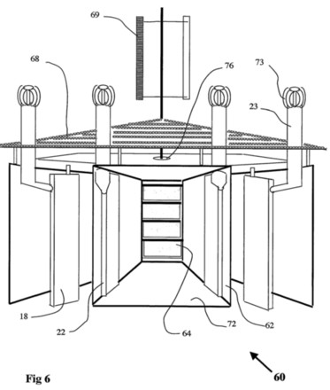
[0011]
FIG. 6 is a plan view of a further embodiment of a wind
turbine of the present invention as used in the third
embodiment of apparatus illustrated in FIG. 5;
[0012]
FIG. 7 is a side elevation of a fourth embodiment of an
apparatus of the present invention;
[0013]
FIG. 8 is a plan view of a yet further embodiment of a
wind turbine of the present invention used in the fourth
embodiment of apparatus illustrated in FIG. 7;
[0014]
FIG. 9 is a schematic side elevation of a compressor
used in the air cooling apparatus of the present invention;
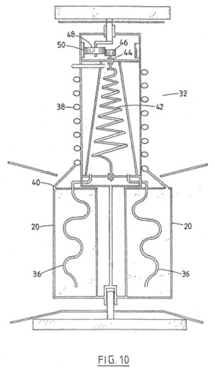
[0015]
FIG. 10 is a schematic side-elevation of a further
embodiment of a compressor used in the air cooling apparatus
of the present invention;
[0016]
FIGS. 11a, b, c and d are various views of the
compressor of FIG. 10;
[0017]
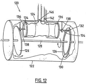
FIG. 12 is a schematic side elevation of a yet further
embodiment of a compressor used in the air cooling apparatus
of the present invention;
[0018]
FIG. 13 is a view similar to FIG. 3 showing a fifth
embodiment of an apparatus of the present invention;
[0019]
FIGS. 14A, 14B and 14C show schematically a scroll
refrigerant compressor useful in the present invention in
various positions;
[0020]
FIG. 15A is a plan view of an alternative form of
scroll compressor useful in the present invention; and
[0021]
FIG. 15B is a side view of the scroll compressor of
FIG. 15A.
DESCRIPTION
OF THE INVENTION
[0022]
In FIG. 1 of the accompanying drawings, there is shown a wind
turbine apparatus 10 comprising a central shaft 12 having a
compressor 13 comprising a housing 14 mounted thereabout. The
compressor housing 14 is arranged to rotate axially relative
to the shaft 12. Further, a plurality of turbine blades 16
(only one of which is shown) are mounted to the compressor
housing 14. As shown, a tube 18 extends outwardly from the
housing 14 to a peripheral cooling coil 20. A convoluted pipe
22 extends from the cooling coil 20 back to the housing 14.
There is a constriction 23 at a part in the pipe 22 adjacent
the cooling coil 20.
[0023]
In use, the turbine blade 16 is caused to rotate axially about
the shaft 12 by the kinetic energy of ambient wind air.
Rotation of the blade 16 causes rotation of the compressor
housing 14 and refrigerant in the compressor housing 14 to be
compressed so as to undergo a phase change from gas to liquid.
The compressed liquid refrigerant flows outwardly driven by
the compressor and assisted by centrifugal force along the
tube 18 to the cooling coil 20 which acts as a manifold.
[0024]
As shown, the refrigerant has to travel almost in a complete
circle to reach the pipe 22. This enables the compressed
refrigerant to be cooled during its residence in the cooling
coil 20.
[0025]
The refrigerant leaves the cooling coil 20 through the
constriction 23 which leads into the pipe 22. At this point
the refrigerant undergoes a rapid loss of pressure and thus
evaporates back to the gaseous phase and causes the blade 16
to be cooled. The spent refrigerant then passes centripetally
back to the housing 14 on a low pressure line of the
compressor 13.
[0026]
The cooling of the blade 16 causes ambient wind air to be
cooled which has useful effects as will be described.
[0027]
In FIG. 2, there is shown an apparatus 30 similar to that in
FIG. 1. In FIG. 2 there can be seen a plurality of turbine
blades 16, a plurality of tubes 18, a cooling coil 20 and a
plurality of pipes 22. In this embodiment, the compressed
refrigerant passes along the tubes 18 to the cooling coil 20.
From the cooling coil 20 the compressed refrigerant passes
through a plurality of short tubes 28 to an inner manifold 26.
From the inner manifold 26 the compressed refrigerant passes
through the constrictions 23 into the tubes 22 as described
hereinabove. Thus the compressed refrigerant does not enter
the tubes 22 directly and therefore is cooled by its residence
in the cooling coil 20 and the tubes 28 and the inner manifold
26.
[0028]
In FIG. 3, there is shown an apparatus 40 which comprises a
wind turbine 10. There is also shown a respective inner
manifold 26 adjacent an outer end of each blade 16. The
compressed liquid refrigerant passes initially from the
cooling coil 20 to each inner manifold 26 through short tubes
28. The refrigerant then passes through constrictions 23 into
the pipes 22 as described hereinabove.
[0029]
Further, there is shown in FIG. 3, a wind collecting duct 42
and an outlet condensation chamber 44. The duct 42 includes an
outer wide portion 46 and an inner relatively narrow portion
48. The combination of the wide portion 46 and the narrow
portion 48 increases air velocity in the duct 42.
[0030]
Ambient wind air blowing in the direction of an arrow 50 flows
through the wind turbine 10 so as to cause the latter to
rotate such that the blades 16 are cooled. This causes the air
temperature to fall below the condensation point or dew point
and water vapour to condense from the ambient air to form
liquid water. This is enhanced by the presence of baffles 52
which impede the flow of air and induce liquid water to
collect thereon. The liquid water flows from the baffles 52
onto a sloping floor portion 54 from which the liquid water
flows into a collection trough 56. The cooled air from which
water has been removed is exhausted through an upper outlet
58. As can be seen in FIG. 3, the coil 20 is located
externally of the duct 42 so that heat lost from the
compressed refrigerant is dispersed into the ambient air
rather than inside the duct 42.
[0031]
In FIG. 4, there is shown an apparatus 60 similar to that in
FIG. 3, except that an inlet 62 is lowermost and is provided
with flaps 64. In this case, the flaps 64 are only opened, as
shown, on the windward side of the apparatus 60. Wind air
flows upwardly through the turbine 10 and then through a
condensation chamber 66 to exhaust through a top vent 68. Once
again liquid water collects on baffles 52 and then flows along
a sloping floor 54 to collect in a trough 56.
[0032]
In FIG. 5, there is shown an apparatus 70 similar to that in
FIG. 4, except that the exhaust vent 68 is provided with an
additional wind turbine 72 to reduce pressure in the exhaust
vent 68 and enhance removal of exhaust air. Power obtained
from the wind turbine is available for any useful purpose.
[0033]
In FIG. 6, there is shown a wind turbine 10 having wind guides
62 with flaps 64 between adjacent pairs of wind guides 62. The
flaps 64 are arranged to be opened as shown by the wider
oblong shape when the flaps face in the direction of the
ambient wind.
[0034]
In FIG. 7, there is shown an alternative form of the apparatus
of the present invention
[0035]
In this Figure there is shown an apparatus 80 having a funnel
82 at an intermediate level and a downwardly directed
deviation device 84. The device 84 is arranged to pivot about
a substantially vertical axis so as to orientate itself, in
use, into a position which is most effective in directing the
ambient wind air through a wind turbine 10. Cooled air can
then enter a condensation chamber 86 below the wind turbine 10
and deposit moisture on baffles 88. The deposited moisture can
then flow into a collection trough 90. The cooled air depleted
of moisture can then pass upwardly to an upper vent 92.
[0036]
In FIG. 8, there is shown a wind turbine 10 similar to that
shown in FIG. 7. As shown, the device 84 faces the incoming
ambient wind. The wind air is directed into the wind turbine
10.
[0037]
In FIG. 9, there is shown a preferred form of compressor 90 of
the present invention. The compressor 90 has a central
rotating cylindrical hub or housing 92 on which is mounted the
blades 16 and refrigerant carrying tubes of the wind turbine
10 as described herein. The compressor 90 includes compressor
blades 94 mounted on a drive shaft 96. The blades 94 are
arranged to be driven at high speed by a gear train 98 fitted
to an inner wall of the hub 92. Used refrigerant returning
centripetally to the compressor 90 as described above is
recompressed and sent out centrifugally as described above.
[0038]
In FIG. 10 there is shown an alternative form of compressor
100 mounted within a cylindrical hub or housing 102. In this
embodiment refrigerant is displaced by a roller 104 mounted
eccentrically on a shaft 106 relative to a main shaft 108 of
the compressor 100.
[0039]
As shown in FIGS. 11a, 11b, 11c and 11d, the compressor 100
operates as follows. The compressor 100 comprises a central
shaft 101 having an eccentric 102 mounted thereon. A rotatable
housing 103 is mounted about the eccentric 102. A tube 104
leads away from the housing 103 and a pipe 105 leads into the
housing 103. A spring biased vane 106 extends through a wall
of the housing 103 and contacts an outer surface of the
eccentric 102. Rotation of the housing 103 causes refrigerant
contained therein to be compressed and exited through the tube
104. Similarly, used refrigerant returns to the housing 103
through the pipe 105. This is facilitated by the vane 106
which is spring biased into engagement with the outer surface
of the eccentric 102.
[0040]
In FIG. 12 there is shown a further alternative form of
compressor 120 mounted within a cylindrical hub 122. In this
embodiment refrigerant is contained in an elastic chamber 124.
The chamber 124 is alternately contracted and expanded. This
is done by eccentric discs 126 fixedly mounted on a central
shaft 128. Each disc 126 has a circular channel 130 formed on
an inner side thereof A slidable bearing 132 is mounted in
each channel 130. A respective rod 134 extends from each
bearing 132 to a respective end plate 136 of the chamber 124.
Each rod 134 is constrained by a circular guide member 138.
[0041]
In use, a hub 122 rotates axially about the shaft 128 and the
chamber 124 rotates with the hub 122. This movement causes the
bearings 132 to slide in the channels 130 and the rods 134 to
reciprocate correspondingly in the guide member 138. In this
way the chamber 124 is expanded and retracted so alternately
compressing and driving out compressed refrigerant through a
one way valve 140 and allowing ingress of used refrigerant
through a one way valve 142.
[0042]
In FIG. 13, there is shown a wind turbine apparatus 130 which
is similar to that shown in FIGS. 4 and 5. In this embodiment,
wind funnels 132 are arranged to direct ambient wind air over
a water surface 134. The water may be brackish or fresh water.
The wind air then passes upwardly through an upright tube 136
(or a sloping duct on a hillside) to pass through a wind
turbine 10 and thence a condensation chamber 138 having
baffles 52 and a sloping floor 54 from which water flows into
a collection trough 56. Exhaust air is vented through an
outlet 58. Absolute humidity of air entering the apparatus 130
increases and the density of the air is therefore lowered.
Thus, flow of air due to the wind is augmented by convection
as the wet air rises to the wind turbine 10.
[0043]
It is also envisaged that the refrigeration compressor used in
the apparatus of the present inventions could be in the form
of a scroll compressor.
[0044]
This embodiment of the present invention is illustrated in
FIGS. 14A, 14B and 14C of the accompanying drawings.
[0045]
In FIG. 14 there is shown a scroll compressor 150 having a
housing 151 having mounted therein a circular plate 152.
Further, an internal ring gear 154 mounted on a wind turbine
axial shaft (not shown) extends around the internal periphery
of the housing 151. Turbine blades 16 are mounted to the
housing 151 and cause wind to effect axial rotation of the
housing 151 on a fixed shaft (not shown).
[0046]
The housing 151 is rotated, in use, by rotation of blades of a
wind turbine as described hereinabove.
[0047]
As indicated above, the scroll compressor 150 is mounted on a
bearing on the fixed axial shaft (not shown). One scroll 156
is attached to the housing 151 whilst another 158 is driven by
three planetary gears 160 mounted on the housing 151 disposed
at the apex of an equilateral triangle. The gears 160 are
driven by the ring gear 154. The scroll 158 maybe described as
a wobbling scroll.
[0048]
The gears 160 are asymmetrically connected to the plate 152 by
means of respective pivotal connections 162. In use the
housing 151 is axially rotated by the wind turbine. This
causes the planetary gears to be turned by engagement with the
fixed ring gear 154. This causes the ring gear 154 to rotate
and thereby cause rotation of the planetary gears 160.
Rotation of the planetary gears 160 causes the plate 152 to
move in a wobbling motion which causes the scroll 158 to move
correspondingly.
[0049]
As shown in FIGS. 14A to 14C this causes gaps between the two
scrolls 156 and 158 to be alternately opened up and closed in
a progressive manner. This action leads to compression of
refrigerant vapour contained between the scrolls such that the
vapour is subjected to increased pressure and is converted-to
liquid form.
[0050]
As described hereinabove, the compressed liquid refrigerant is
thus urged outwardly of the compressor housing 151 through a
tube (not shown) by centrifugal-force. Further, as described
hereinabove, the spent refrigerant returns through pipes (not
shown) to the interior of housing 151 where it enters the gap
between the scrolls 156 and 158.
[0051]
In FIGS. 15A and 15B there is shown an alternative arrangement
of scroll compressor 180 useful in the present invention
compared to the scroll compressor of FIG. 14. Like reference
numerals denote like parts. It should be noted in FIG. 15A
that only the scroll 158 is shown.
[0052]
In this embodiment there is a central shaft 182 having mounted
thereon a housing 184. The housing is mounted on a bearing on
the shaft 182. The shaft 182 may or may not be continuous. A
central gear wheel 186 is fixedly mounted about the shaft 182.
The gear wheel 186 is connected to three planetary gears 188.
[0053]
Further, as can be seen in FIG. 15B one scroll 156 is fixed to
the housing 184 by any suitable means such as an end plate
(not shown). The other scroll 158 is mounted on an end plate
190 and is connected to the planetary gears 188 through
eccentric pins 192.
[0054]
The shaft 182 and the gear wheel 186 are fixed in position.
The housing 184 is arranged to rotate about the shaft 182 as
described hereinabove. The planetary gears 188 engage with the
gear wheel 186 and are thereby caused to rotate as the housing
184 rotates. This rotation of the planetary gears 188 causes
the scroll 158 to move on the plates 190 by means of the pins
192 such that the scroll 158 undergoes a wobbly motion as
described hereinabove.
[0055]
Modifications and variations as would be apparent to a skilled
addressee are deemed to be within the scope of the present
invention.
http://v3.espacenet.com/textdoc?DB=EPODOC&IDX=EP1907637&F=0
GUST
WATER TRAP APPARATUS
EP1907637
2008-04-09
Also published as: WO2007009184 (A1) // EP1907637 (A0)
// AU2006272459
http://v3.espacenet.com/textdoc?DB=EPODOC&IDX=WO2007098534&F=0
APPARATUS
FOR PURIFICATION OF WATER
WO2007098534
2007-09-07
Apparatus for purification or water having an evaporation
chamber (3), a roof (5) and a condensation chamber (8) and
wind air inlet means (14, 15). The evaporation chamber (3)
contains a body of impure water (2) and the roof (5) can
transmit solar radiation. The solar radiation heats the impure
water, increases evaporation and wind air from the wind air
inlet (14, 15) moves the water laden air into the condensation
chamber (8) where water condenses.
CROSS-AXIS WIND TURBINE ENERGY CONVERTER
WO2007068054
2007-06-21
The invention relates to a wind energy converter apparatus
(10) which comprises an incoming wind guide (12), a cross-axis
wind turbine (18), a wind containing region (16) and a wind
outlet (24). Preferably, means is provided for cooling the
wind air to enhance precipitation of moisture from the wind
air in the apparatus.
Apparatus
and method for cooling of air
AU2005274673
CN101014817