Considering the
history of Russian electrical engineering, let's remember the
great Russian scientist Pavel Nikolaevich Yablochkov.
Pavel Nikolaevich was born on September 14, 1847 in the
Saratov province. He was trained as a military engineer and
served as an officer from 1866 to 1872. In 1875 Yablochkov
went to the World's Fair of Inventors in Philadelphia to show
the world his new unusually powerful electromagnet. However,
he stayed to work in the famous Breguet watch workshop in
Paris. In France, Yablochkov patented his inventions and
became one of the founders of the French Electrotechnical
Society.
Yablochkov's first patent No. 110479, dated November 29, 1875,
was issued by the French government for an "electromagnet". A
distinctive feature of the Yablochkov electromagnet was that
its winding consisted of a flat copper tape wound on one edge
so that the plane of the tape was perpendicular to the core.
Such an electromagnet was unusually strong compared to other
electromagnets of the time.
The fact is that winding flat copper tape "edge on core"
allows for a large number of ampere-turns per unit length of
core, which provides a high magnetic field strength. To get
more ampere turns, the electromagnetic coil is usually wound
with a small diameter round wire, but this increases the ohmic
resistance and heat loss of the winding. The Yablochkov
transformer provides a small electric resistance (low ohmic
losses) and a large number of ampere-turns per unit length of
the core in the winding.
Note that flat wires increase the efficiency of transformers
and can be used in designs with asymmetrical mutual induction.
A flat conductor can be wind as the secondary winding of a
transformer. In Fig. 36 shows how the field of a flat turn of
the secondary winding B2 interacts with the field B1 of the
primary coil of the transformer. In this transformer,
conditions are created for the asymmetry of magnetic fields.
The secondary field has no effect on the primary source, so
the load in this transformer has no effect on the primary
source. In fact, we can put more power into the load but the
consumption power from the primary source will be much less.
Fig. 36. Asymmetry of fields in flat coils
Yablochkov's second patent No. 111535, dated February 17,
1876, also mentions the use of a flat tape winding. Note that
Tesla and other inventors later also used flat wires in the
windings of transformers and electric motors, including the
Mobius scheme.
On March 23, 1876, Yablochkov received a patent for a lighting
lamp, the so-called "Yablochkov candle".
In 1877 he received a French patent for a magnetic
dynamo-electric alternating current machine in which the coils
of wires are stationary. The rotation of the toothed iron disk
caused changes in the magnetic flux. In fact, it is one of the
first high performance generator designs (today we name it as
alternators). This device generates the electromotive force
but it does not decelerate the rotor. So, it can be high
efficient and overunity. After 1877, Yablochkov's scheme was
repeated by many inventors in their designs of free energy
generators. Today we call such devices "generators without
back EMF". In such generators, a low power motor can drive a
much higher power generator. So, this motor-generator system
can be autonomous and work without an external power source.
We also have to mention his priorities in the invention of the
world's first electromagnetic energy transformer for
industrial use, French patent No. 115793 dated November 30,
1876. In addition to the French patent, Yablochkov received
Russian and German patents on April 6, 1878 for the world's
first electromagnetic energy transformer. In the German
history of transformers, Uppenborn writes: “In 1878 we
encounter the first industrial use of induction coils for
lighting; that year Yablochkov accepted the German patent No.
1630, which he used to power his lamps. "
It is important for developers of free energy generators to
know that Yablochkov found a way to use air (ionization of the
environment) as a "source of free electrons" to increase the
power in the circuit of lighting lamps.
On September 13, 1877, Professor Egorov published a report in
the Russian Physicochemical Society on Yablochkov's
inventions, including the question of "introducing large
capacitors in the generator circuit to increase the power of
the lamps".Fig. 37 shows a diagram of the distribution of
alternating current with capacitors according to the French
patent No. 120684 of October 11, 1877 for "A system for
distributing and amplifying currents by atmospheric
electricity coming from one power source for the simultaneous
supply of several Lamps ".
Fig. 37. Amplifying currents by atmospheric electricity
In the book "Electric Lighting" published in 1883, De Monsel
writes: "In order to increase the light output of electric
candles, Yablochkov came up with the idea of using capacitors
with a large surface area."
Note that in addition to flat plates, Yablochkov used special
"needle capacitors", so to speak "hedgehogs", similar to
brushes with metal needles. It is known that the tip of the
electrode improves air ionization conditions. The ionization
of air is necessary to introduce additional free electrons
into the circuit in order to increase the strength of the
current.
Yablochkov explained: “I force the dynamic electricity
supplied by the energy source to undergo a double conversion -
first into static electricity and then back into dynamic
electricity. The wire coming from the alternating current
machines must be connected to the inner electrode of the
Leiden capacitor or the capacitor of a special device and the
second wire to be connected to the lamp. The addition of the
capacitors not only allows energy to be distributed in
different directions, but also has the goal of creating
atmospheric electricity that accumulates in the capacitors...
Therefore, the sum of the amount of electricity sent to the
light sources is greater than the current drawn by the
original energy source is generated. "
A similar solution can be found in modern designs of high
voltage free energy generators. During their operation, air
ionization is detected (Swiss generator "Testatika" in
Methernitha) or the authors use the ground connection as a
source of free electrons (Kapanadze generators). The
perforated metal elements of the TESTATIKA generator arean
analogy of the Yablochkov needle "hedgehogs" capacitors.
Russian academician Nikolai Dmitrievich Papaleksi, dating back
to the 50s of the last century. He wrote about the possibility
of achieving the parametric generator efficiency "much more
than 99%".
The greatest French physicists of the time, for example
Mascard and Warren-Delarue, were present at Yablochkov's
experiments and found that the sum of the currents from the
capacitor plates into the ground was twice that of the primary
generator. Notice that they write of "currents coming from the
ground". A large number of free electrons, which are set in
motion by a change in electrical potential in a single-core
electrical line, can only be provided if the circuit is
grounded and a "large-area capacitor" is present which "stores
atmospheric electricity".
Grounding is a source of free electrons and a condition for
generating high currents in the payload circuit. This
principle is used in many free energy generators, for example
by Kapanadze. This principle also applies to single-wire power
lines developed by scientists from the Institute for
Electrofication of Agriculture in Moscow (authors Avramenko,
Strebkov, etc.).
It is interesting to note that the electrical lighting systems
of Yablochkov times were single-wire, meaning they only had
one wire and the other end of the wire was connected to
ground. Later we will look at a similar modern power line that
uses only one wire. In the days of Yablochkov there was no
electricity power meter, payment was made at a fixed price
(subscription fee).
The second factor to consider for Yablochkov’s inventions is
resonance. The presence of inductances and capacitors in the
circuits can increase voltage in resonance mode. In fact,
Yablochkov was the first to use resonance transformers in
Russia as a combination of inductors and powerful capacitors.
Yablochkov was the founder of the French Society of Electrical
Engineers, but he sold all of his shares and bought his
inventions from the French Society for one million francs to
get rights for development of these technologies in Russia.
Yablochkov came to St. Petersburg and founded a company there
called “Yablochkov-Inventor and Company. Association for
electrical lighting and the manufacture of electrical
appliances and machines in Russia”. Yablochkov built a factory
in St. Petersburg that manufactured transformers and lighting
systems. The Russian Navy actively took advantage of
Yablochkov's inventions. The English press wrote that the
success of the Russians in the naval wars was largely
determined by the use of electrical lighting and electrical
machines on Russian warships.
In 1887, Yablochkov received a patent for a galvanic cell that
uses hydrogen and oxygen to generate electricity. It was one
of the first fuel cells in the World to be widely used now in
21st century.
It is known that Yablochkov was interested in aviation and
methods of creating a driving force (traction) for cars. He
was granted a patent for an electric car, which modern
engineers are currently working on to produce.
Yablochkov's patents are extremely important for developers of
high-efficiency power generators. His idea that the current
intensity in the lamp circuit can be increased by "atmospheric
electricity" is implemented in many modern projects of energy
sources with an efficiency of more than 100%.
New Energy Technology, Vol. 1, p. 68
Power Output can be More than Power Input
by Alexander V. Frolov
Pavel N. Yablotchkov was born in 1847 near Saratov, Russia. He graduated as a Military Engineer in 1866 and spent several years in the Russian Army. In 1872 he came to Moscow and started his activities in the electrotechnical field. From 1875 he worked in Paris with well-known Louis Breget and his first patent in France # 110479 (29 November 1875) was about an electromagnetic transformer. Then he patented and developed a lighting system (the famous Yablotchkov’s electrical candle). In 1887 he patented a new electromagnetic transformer for industrial applications, France # 115793 (30 November 1876).

The most interesting patent claim for over-unity by Pavel Yablotchkov is known as France patent # 120684 (11 October 1877), The System of Distribution and Amplification of Electrical Currents by Means of Atmospheric Electricity. The patent describes special capacitors connected in series with the load, to increase output current by means of ionization. Experiments were produced together with well-known physicists (such as Dr Maskar, Dr Varren-Delaru and others) and they confirmed 200% efficiency of the circuit. Let’s try to explain the method. Figure 1 is a schematic drawing from Yablotchkov’s patent. The Leyden jar is not a symmetrical capacitor, i.e., it is different in principle from a two-plate flat capacitor. The inner electrode of the jar should be connected to a high voltage source and in this case the changes of [ … missing text in original… ].

In the opposite case it does not work and if you connect a high voltage source to the external cathode no potential changes will be detected on the inner electrode. Connection to ground or to a special plate (that is covered by many needles to increase air ionization) is necessary to collect the maximum electrons on the plate surface or to return the maximum electrons from the plate surface when changes of potential in the external electrode are produced by means of electrical induction in the Leyden jar.
As a conclusion I should note that one more supposition about the secrets of the well-known Swiss M-L converter (Methernitha). The main elements of the design are Leyden jar capacitors, which have the external surface made of perforated metal.
The other known fact is that great ionization of air is
observed when the converter is in operation. So, the
electrostatics machine can produce pulses of very high voltage
(potential difference) but it can’t be used as a source of
powerful current. We should use some method to increase the
current in the circuit and Yablotchkov’s technology is quite a
good idea for this. A large surface of external electrode of
the Leyden jar can solve the problem. Maximum strong
ionization allows us to get output current several times
stronger than the weak current from the electrostatic machine.
"M. Jablotchoff has proposed to use for the divisibility of light sources, the AC of the magneto-electric machine of the more intercalated light sources not directly between the poles, but by the capacitors or Leyden jars.
"In Figure 36-1 we see the assumption of interspersed light sources through the earth and in Figure 2 is taken as pole weary land and sources of light are intercalated between the outer frame of the Layden jarsand earth, or between the branch of the armatures of the bottle (Figure 3).
"In the latter two cases M. Jabochkoff intended to use atmospheric electricity to increase the action of the machine."
Paul
JABLOCHKOFF
A New
System of Distributing and Increasing with Atmospheric
Electricity Currents proceeding from a Single Source of
Electricity for the purpose of Supplying several Lighting
Centres
December
1877
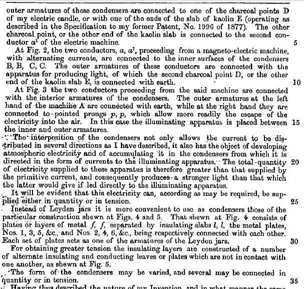
My Invention has for its object the distribution of electric
currents proceeding from a single source of electricity for
the purpose of supplying at the same time a number of
illuminating apparatus, and at the same time to strengthen
such currents by means of atmospheric electricity.
In order to obtain useful results from a current proceeding
from a source of dynamic electricity instead of operating
directly with the said currents as heretofore, I, according
to my present Invention, cause the same to undergo a double
transformation by firstly converting the dynamic electricity
into statical electricity, and then reconverting this
into dynamic electricity, and it is by means of the latter
current that I obtain useful results. For the above purpose,
instead of closing the circuit of a source of electricity by
means of a continuous conductor as heretofore, I unite the
conductor coming from one of the poles of the electrical
source with one of the armatures of a condenser, composed of
one or more Leyden jars of large surface, or constructed as
will be presently described.
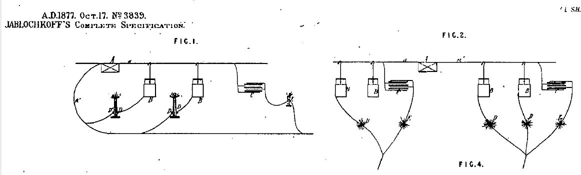
The other conductor is connected in various ways, of which
the principal ones are shown in the accompanying Drawings.
At Figure 1, the one conductor a, proceeding from a
magneto-electric machine A ( giving alternating currents )
is connected with the interior surfaces of several Leyden
jars B, B, or of the condenser C, which is of a particular
construction. The outer armatures of these condensers are
connected to one of the charcoal points D of my electric
candle, or with one of the ends of the slab of kaolin E (
operating as described in the Specification of my former
Patent, No. 1996 of 1877 ). The other charcoal point, or the
other end of the kaolin slab is connected to the second
conductor a1 of the electric machine.
At Figure 2, the two conductors, a, a1, proceeding from a
magneto-electric machine, with alternating currents, are
connected to the inner surfaces of the condensers B,B,C,C.
The outer armatures of these conductors are connected with
the apparatus for producing light, of which the second
charcoal point D. or the other end of the kaolin slab E, is
connected with earth.
At Figure 3 the two conductors proceeding from the said
machine are connected with the interior armatures of the
condensers. The outer armatures at the left hand of the
machine A are connected with earth, while at the right hand
they are connected to pointed prongs p, p, which allow more
readily the escape of the electricity into the air. In this
case the illuminating apparatus is placed between the inner
and outer armatures.
The interposition of the condensers not only allows the
current to be distributed in several directions as I have
described it, it also has the object of developing
atmospheric electricity and of accumulating it in the
condensers from which it is directed in the form of currents
to the illuminating apparatus. The total quantity of
electricity supplied to the apparatus is therefore greater
than that supplied by the primitive current, and
subsequently produces a stronger light that that which the
latter would give if led directly to the illuminating
apparatus.
It will be evident that this electricity can, according as
may be required, be supplied either in quantity or in
tension.
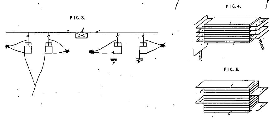
Instead of Leyden jars it is more convenient to use as
condensers those of the construction shown at Figures 4 and
5. That shown at Figure 4 consists of plates or layers of
metal f, f, separated by insulating slabs l,l, the metal
plates, Nos. 1, 3, 5, &c., and Nos. 2, 4, 6,
&c., being respectively connected with each other. Each
set of plates acts as one of the armatures of the Leyden
jars.
For obtaining greater tension the insulating layers are
constructed of a number of alternate insulating and
conducting leaves or plates which are not in contact with
one another, as shown at Figure 5.
The form of the condensers may be varied, and several may be
connected in quantity or in tension...