Xin An ZENG
Electric Field Sterilization & Chemical Acceleration
New Scientist
# 2687
17
December 2008
How to Make Cheap Wine Taste Like a Fine Vintage
How do you turn a bottle of cheap plonk into a fine vintage?
MOST people have got one lying around somewhere: a bottle of cheap, nasty wine left over from a dinner party just waiting to be offloaded on someone else - or quaffed late one night when the good stuff has run out. But what if you could turn that bargain-basement plonk into fine wine in minutes? In these straitened times it could be just the thing a wine lover needs.
Traditionalists, of course, would insist that nothing can replace genuine quality plus long, slow ageing in an oak barrel and years of storage in cool, cobwebby cellars. But could there be a short cut? Over the years, inventors have come up with dozens of widgets that they claim can transform the undrinkable or bring the finest wines to perfection without the long wait. Sadly, there's little scientific evidence that most of them work
Looks like you're stuck with the plonk.
Or are you? Fortunately, there is one technique that stands out from the rest. It is backed by a decade of research, the results have been published in a peer-reviewed journal and the end product has passed the ultimate test- blind tasting by a panel of wine experts. No fewer than five wineries have now invested in the technology.
The secret this time is an electric field. Pass an undrinkable, raw red wine between a set of high-voltage electrodes and it becomes pleasantly quaffable. "Using an electric field to accelerate ageing is a feasible way to shorten maturation times and improve the quality of young wine," says Hervé Alexandre, professor of oenology at the University of Burgundy, close to some of France's finest vineyards.
No matter how impatient or undiscriminating you may be, fresh wine is undrinkable and can have horrible after-effects. Expect an upset stomach, a raging thirst and the world's nastiest hangover. The youngest a wine can be drunk is six months. Most, especially reds, take longer to achieve the required balance and complexity. The finest can take 20 years to reach their peak.
During ageing, wine becomes less acid as the ethanol reacts with organic acids to produce a plethora of the fragrant compounds known as esters. Unpleasant components precipitate out and the wine becomes clearer and more stable. Red wines mellow as bitter, mouth-puckering tannin moleculescombine with each other and with pigment molecules to form larger polymers, at the same time releasing their grip on volatile molecules that contribute to the wine's aroma.
These reactions take time and need a small but steady supply of oxygen. In barrel-aged wines, oxygen leaks through the wood, while wine matured in steel tanks is often helped along by introducing microscopic oxygen bubbles.
There are good commercial reasons why winemakers would love get their hands on a speedier alternative, especially in places like China where the industry is young and booming. It would allow them to get their wines into the shops faster to meet ever-increasing demand, and cut the cost of storage.
The food industry
has experimented with electric fields as an alternative to
heat-treating since the 1980s, and 10 years ago
Xin An
Zeng , a chemist at the South China University of
Technology in Guangzhou, decided to see what he could do for
wine. Early results were promising enough for Zeng and his
colleagues to develop a prototype plant in which they could
treat wine with fields of different strengths for different
periods of time.
They pumped the wine
through a pipe that ran between two titanium electrodes, fed
with a mains-frequency alternating supply boosted to a higher
voltage. For the test wine, the team selected a 3-month-old
cabernet sauvignon from the
Suntime Winery, China's largest producer. Batches of wine
spent 1, 3 or 8 minutes in various electric fields. The
team then analysed the treated wine for chemical changes that
might alter its "mouth feel" and quality, and passed it to a
panel of 12 experienced wine tasters who assessed it in a
blind tasting (Innovative Food Science and Emerging
Technologies , vol 9, p 463 ).
The results were striking. With the gentlest treatment, the harsh, astringent wine grew softer. Longer exposure saw some of the hallmarks of ageing emerge- a more mature "nose", better balance and greater complexity. The improvements reached their peak after 3minutes at 600 volts per centimetre: this left the wine well balanced and harmonious, with a nose of an aged wine and, importantly, still recognisably a cabernet sauvignon.
Two other good things happened: the breakdown of proteins produced free amino acids that contribute to taste and there was a noticeable reduction in the levels of aldehydes, which are responsible for "off" flavours. You can have too much of a good thing, though. Upping the voltage and applying it for longer brought new and unwanted changes, including the generation of new undesirable aldehydes. Zap it too much and the result, the panel found, was worse than the untreated original.
Although Zeng cannot yet explain how exposure to an electric field alters the wine's chemistry, his results show that under the right conditions the technique can accelerate some aspects of the ageing process. "Not only can it shorten a wine's normal storage time, it can also improve some lower-quality wine," he says. "It works just as well with other grape varieties such as merlot and shiraz." Five Chinese wineries have begun trials.
A quick blast with an electric field can improve lower-quality wine and shorten storage time.
Sadly for wine drinkers feeling the pinch, there's no immediate prospect that you can try this for yourself. "I have thought of designing a set of equipment for use at home," admits Zheng "...but not yet."
Innovative Food Science & Emerging Technologies -- Volume 9, Issue 4, October 2008, Pages 463-468
The Effects of AC Electric Field on Wine Maturation
Xin An Zenga, Corresponding Author Contact Information, E-mail The Corresponding Author, Shu Juan Yua, Lu Zhangb and Xiao Dong Chenc
a College of Light Industry and Food Sciences, South China University of Technology, Guangzhou 510640, PR China
b Department of Chemical and Materials, Faculty of Engineering, The University of Auckland, New Zealand
c Departement of Chemical Engineering, Faculty of Engineering, Monash University, Clayton, VIC 3800, Australia
Abstract -- A
pilot plant scale innovative technique applying AC high
voltage electric field to accelerate wine aging of Young
Cabernet Sauvignon is reported in this paper. The design
principles, equipment configuration and its effect on wine
taste and flavour are presented. Results from a sensory
evaluation group demonstrated that there were various effects
on the wine quality under different conditions, some positive
while others negative. An optimum treatment, with electric
field 600 V/cm and treatment time 3 min, was identified to
accelerate wine aging, which made the harsh and pungent raw
wine become harmonious and dainty. HPLC and GC/MS combined
with routine chemical analysis methods were used to identify
the differences between the treated and untreated samples. It
was found that the contents of higher alcohols as well as
aldehydes in volatile compounds decreased to a large number,
meanwhile, the contents of esters and free amino acids
slightly increased while others remained unchanged through all
treatments. The results of this study show that the technology
of accelerating wine aging by high voltage electric field is a
feasible method to shorten wine maturing process times and to
improve the quality of a young wine, if favourable process
conditions are chosen.
Industrial relevance
The application of physical treatment methods other than heat, such as electric field, magnetic field, ultrasonic wave and microwave, etc., for green processing of foods, is becoming popular. AC electric current is of continuous wave form, thus being seldom used in food processing. However, numerous previous studies about the effect and mechanisms of accelerating wine aging with high voltage AC electric field have been conducted in the Laboratory of South China University of Technology. This manuscript presents the effect of high intensity AC electric field on young wine’s physicochemical properties and sensory quality. The results presented in this paper show that it is a promising and novel technology to shorten the young wine’s aging period. Recently, a few of the Chinese winery companies have already started to set up the plant scale equipment.
Corresponding Author
-- Contact Information :
Tel.: +86 20 87113668; fax: +86 20 87112668
XIN AN ( "ANDY" ) ZENG

Birth date: Oct.
1972
Birth place: Hu Nan province, China
Blood type: O
Tel: 0086-20-87113668 (o)
Address:
Room 13339,
Building 13
Campus of
South China University of Technology
No.381,
Wushan Road
Guangzhou
City
P.R.China,
510640
e-mail: xazengscut.edu.cn
CN1623448
Prepolarized Pulse Electric Field Disinfectant
Method and its Equipment
Inventor: ZENG
XINAN [CN] ; FU XIONG
Applicant: UNIV SOUTH CHINA TECH
2005-06-08
Inventor(s): ZENG XINAN [CN]; FU XIONG [CN]; YU SHUJUAN
[CN]
Applicant(s): UNIV SOUTH CHINA TECH [CN]
Classification: - international: A23L3/00;
A23L3/32; A23L3/00; A23L3/32; (IPC1-7): A23L3/32; A23L3/00
Also published as: CN1285291 (C)


Abstract -- A prepolaried pulsive electric field method for sterilizing material includes such steps as prepolarizing the raw material in an electrostatic field, and sterilizing in a high-voltage pulsive electric field. Its equipment is composed of raw material tank, pump, vacuum degassing unit, high-voltage electric pulse generator, electric pulse treating chamber, and prepolarizing unit. Its advantage is high effect to kill bacteria and deactivate enzyme.
CN1635100
Process for Accelerating Ageing of Brandy Oak
by Electromagnetic Field
Inventor: ZENG
XIN AN [CN] ; GENG YUHUAN
Applicant: UNIV SOUTH CHINA TECH
2005-07-06
Also published as: CN1303199 (C)

Abstract -- The invention discloses a method for accelerating ageing of brandy oak by electromagnetic field, which mainly consists of placing the brandy cask into 10-30KV/m electromagnetic fields for aging treatment, the apparatus comprises an electromagnetic field regulator assembly and an ageing treatment charber, wherein the electromagnetic field regulator assembly comprises an automatic alarm circuit breaking component, a voltage-stabilizer, a frequency regulator and a voltage adjusting magnifier, the ageing treatment chamber comprises an electrode plate, an insulating frame and a cask, the cask is arranged between the electrode plates.
[ Shades of Leon SPRINK : Space Activator ! ]
CN1411871
Processor of Pulse Electric Field Sterilizing
Equipment
Inventor: ZENG
XIN AN [CN] ; LI GUOJI
Applicant: HUA NAN UNIV OF SCIENCE & ENGI
2003-04-23
Also published as: CN1194765 (C)
Abstract -- The present invention relates to a treatment device of equipment for sterilizing liquid products in the fields of food, biological, pharmaceutical and chemical industries by adopting high-intensity pulse electric field. Said treatment device is formed from material-treating cavity, two electrodes mounted in the material-treating cavity, inlet and outlet, in which said material-treating cavity is vacuum cavity, and can obtain good sterilizing effect.
CN1354018
High-voltage pulse electric field
sterilization method and its equipment
Inventor: ZENG
XIN AN [CN] ; FU XIONG
Applicant: HUA NAN UNIV OF SCIENCE & ENGI
2002-06-19
Also published as: CN1174691 (C)

Abstract -- The present invention relates to a sterilization method by using high-voltage impulse electric field. The sterilization equipment designed according to said method is formed from high-voltage impulseelectricity generation device, parameter measurement, display and regulation and control device and high-voltage impulse electric field treatment chamber. In the course of sterilization it does not utilize thermal power to kill microbe, but makes the material to be sterilized pass through the high-voltage impulse electromagnetic field. The microbe can be acted by strong electromagnetic field force in a short time, its cell structure can be broken by potential difference between cell membranes so as to make thallus die.
CN2379480
Pipeline Type High Voltage Electro-Magnetic
Field Quick Aging-Promoting Equipment for Wine
Inventor: ZENG
XIN-AN [CN] ; LI GUOJI
Applicant: HUA NAN SCIENCE & ENGINEERING
2000-05-24

US5690978
HIGH VOLTAGE PULSED ELECTRIC FIELD TREATMENT CHAMBERS FOR THE PRESERVATION OF LIQUID FOOD PRODUCTS
1998-04-09
Inventor(s): YIN YONGGUANG; ZHANG QINGHUA HOWARD; SASTRY
SUDHIR KARTIKEYA
Applicant(s): OHIO STATE RES FOUND
Classification: - international: A23L3/00;
A23L3/26; A23L3/32; A23L3/00; A23L3/26; A23L3/32; (IPC1-7):
A23L3/00; A23L3/26; A23L3/32 - European: A23L3/00;
A23L3/26; A23L3/32
Also published as WO9814074 //
AU4605697 // EP1028635 // CA2267196
Cited documents: US4723483 (A) US4838154 (A)
US5235905 (A)
Abstract -- A pulsed electric field treatment device for the sterilization and preservation of pumpable food products having at least two electrodes (201, 203) and an insulator (202) and particularly suited for the inactivation of vegetative and bacterial spore micro-organisms. Each electrode includes an electrode flow chamber (207, 208) for making electrical contact with the pumpable food product and for allowing the pumpable food product to flow through the treatment devices. The insulator (202) is situated between the electrodes (201, 203) and includes an insulator flow chamber (206) positioned between the electrode flow chambers (207, 208) and provides for the flow of pumpable food product from one electrode flow chamber to the other. A high voltage pulse generator (107) applies a high voltage signal of variable voltage, frequency and pulse duration to the electrodes.; The electrode and insulator flow chambers may employ a variety of sectional and cross-sectional geometries including tubular, cylindrical, rectangular, elliptical and non-uniform design.
Current U.S.
Class: 426/237 ; 426/521; 99/451; 99/483;
99/DIG.14
Current International Class: A23L 3/00 (20060101); A23L
3/32 (20060101); A23L 3/26 (20060101); A23L 003/00 (); A23L
003/26 (); A23L 003/32 ()
Field of Search: 99/451,483,DIG.14,516,536,358
426/234,237,238,521,410,241,407,247,248 422/22-24 219/700,735
392/338,497
References Cited
[Referenced By]
U.S.
Patent Documents
3876373 April 1975
Glyptis
4524079 June 1985 Hofmann
4695472 September 1987 Dunn et al.
4838154 June 1989 Dunn et al.
5048404 September 1991 Bushnell et al.
5235905 August 1993 Bushnell et al.
5250160 October 1993 Oksman et al.
5282940 February 1994 Griffis et al.
5290583 March 1994 Reznik et al.
5393541 February 1995 Bushnell et al.
5415882 May 1995 Knipper et al.
5447733 September 1995 Bushnell et al.
5514391 May 1996 Bushnell et al.
5527105 June 1996 Riach, Jr.
5534278 July 1996 DeRuyter et al.
5549041 August 1996 Zhang et al.
5562024 October 1996 Polny, Jr.
5603972 February 1997 McFarland
5607710 March 1997 DeRuyter et al.
5630360 May 1997 Polny, Jr.
Foreign Patent Documents
2 513
087 Sep., 1981 FR
3-98565 Apr., 1991 JP
Other References
"Engineering Aspects
of Pulsed Electric Field Pasteurization," Zhang, Qinghua, et
al., Journal of Food Engineering, 25:261-281, 1994. .
"Inactivation of E. coli and S. cerevisiae by Pulsed Electric
Fields Under Controlled Temperature Conditions," Zhang, Q., et
al., 1994 American Society of Agricultural Engineers, vol.
37(2);581-587. .
"Inactivation of Microorganisms in a Semisolid Model Food
Using High Voltage Pulsed Electric Fields," Zhang, Qinghua, et
al., Food Science & Technology (lwt), 1994, 2(6):538..
Description
FIELD OF THE INVENTION
The present invention relates generally to food preservation systems and methods and, more specifically, to a pulse electric field treatment device for inactivating bacteria and microorganisms found in liquid food products.
BACKGROUND OF THE INVENTION
The preservation of food products is an important industrial and commercial activity and is primarily based on the inactivation, or destruction, of microorganisms in the food product. Existing methods of food preservation include the use of salts (i.e. sodium chloride), dehydration, heat pasteurization and freezing to inactivate microorganisms present in the food product. However, many of these processes affect the color, texture, flavor and taste of the foods preserved. For example, heat pasteurization can cause thermal damage to the food product and adversely affect its taste, flavor and nutrient content. As a result of this and other disadvantages, researchers have strived to develop non-thermal food sterilization techniques.
One such non-thermal food sterilization technique is known as Pulsed Electric Field (hereinafter PEF) treatment. Generally, in PEF treatment, an electric field voltage is applied across two electrodes where food material is between the electrodes. Because most liquid food products are primarily composed of water and nutrients such as proteins, vitamins, triglycerides and minerals, a corresponding electric field is induced in the food product and weakens the bacteria's cell structure. The bactericidal effect caused by PEF treatment is best explained by what is known as the Dielectric Rupture Theory.
According to the Dielectric Rupture Theory, PEF treatment reduces the activity of bacteria and other microorganisms by damaging the bacterial or microorganism cell structure. The applied electric field induces an electric potential across the membrane of a living cell. This electric potential, in turn causes an electrostatic charge separation in the cell membrane based on the polar nature of the cell membrane molecules. When this electric potential exceeds a critical value, pores form in weak areas of the cell membrane. When the critical value is exceeded by a large margin, the pore formation and cell membrane damage have a lethal effect on the bacteria or microorganism. However, the lethal effect of PEF treatment is dependent on many factors including, inter alia, the strength and length of time the electric field is applied, treatment temperature and the species of bacteria and/or microorganism to be inactivated. For further information on the engineering aspects of PEF treatment, see Zhang, Q., G. V. Barbosa-Canovas and B. G. Swanson, Engineering Aspects of Pulsed Electric Field Pasteurization, Journal of Food Engineering, Vol. 25 pp. 261-281 (1994).
In particular, the lethal effect of PEF treatment on bacterial spores has heretofore been limited. The limited results are due in part to the bacterial spore's rigid structure and ability to resist unfavorable environmental conditions. Therefore, current PEF treatment methods and devices for the inactivation of bacterial spores have met with only limited success.
SUMMARY OF THE INVENTION
According to the present invention, a pulse electric field (PEF) treatment device is provided for preserving and sterilizing a liquid food product. The PEF treatment device includes a first and second electrode for supplying an electric field to the liquid food product. Each electrode includes an electrode flow chamber for accepting the flow of the liquid food product and for making electrical contact with the liquid food product. The PEF treatment device also includes at least one insulator positioned between the first and second electrodes and for electrically insulating the first and second electrodes from each other. The electrical insulator includes an insulator flow chamber for accepting the flow of liquid food product from the electrode flow chamber of the first electrode and the electrode flow chamber of the second electrode. The electrode flow chamber of the first electrode includes an inlet aperture and an outlet aperture. Similarly, the electrode flow chamber of the second electrode includes an inlet aperture and an outlet aperture. The insulator flow chamber also includes an inlet aperture and an outlet aperture. The insulator flow chamber and the electrode flow chambers are configured to comprise a single tubular flow chamber for accepting the flow of the liquid food product through the PEF treatment device. The insulator flow chamber inlet aperture and the first electrode flow chamber outlet aperture are positioned adjacent to each other and have substantially similar cross-sectional geometry. Similarly, the insulator flow chamber outlet aperture and the second electrode flow chamber inlet aperture are positioned adjacent to each other and have substantially similar cross-sectional geometry.
The present invention also provides a PEF treatment system for preserving and sterilizing a liquid food product. The system includes a high voltage pulse generator for supplying a pulsed electric field, a PEF liquid product treatment device for subjecting the liquid product to the pulsed electric field, a balance tank for storing the liquid food product to be treated, a de-oxygenator device for removing oxygen and other gases from the liquid food product, a pulseless pump for providing a continuous flow of liquid food product in the treatment system, at least one heat exchanger for regulating the temperature of the liquid food product, and an aseptic packaging device for packaging the liquid food product. The PEF liquid product treatment device is in circuit communication with the high voltage pulse generator and includes first and second electrodes for supplying an electric field to the liquid food product and an insulator for electrically insulating the plurality of electrodes from each other. Each electrode includes an electrode flow chamber for accepting the flow of the liquid product and for making electrical contact with the liquid product. The insulator includes an insulator flow chamber for accepting the flow of liquid food product and is positioned between the electrode flow chambers. The insulator flow chamber and the electrode flow chambers are configured so that a single tubular flow chamber for accepting the flow of liquid food product is formed thereby and each have inlet and outlet apertures of substantially similar cross-sectional geometry and adjacent to each other.
The present invention further provides a PEF treatment device having first and second electrodes for supplying an electric field to a liquid product, at least one insulator for electrically insulating the first and second electrodes from each other and an insertion member for providing electrical contact to the liquid product. Each electrode includes an electrode flow chamber for accepting the flow of liquid product and each insulator includes an insulator flow chamber for allowing the liquid product to flow from and to the electrode flow chambers. The electrode flow chambers and the insulation flow chamber are configured and positioned so as to form a single flow chamber for accepting the flow of the liquid product. The flow chambers each have inlet and outlet apertures of substantially similar apertures and are adjacent to each other. The insertion member is positioned within the electrode and insulator flow chambers and includes a plurality of conducting members and at least one insulator member. The plurality of conducting members provide electrical contact to the liquid product and the at least one insulator member provides electrical insulation between the plurality of conducting members. The insertion member includes a cylindrical body that is concentrically located within the single flow chamber that is comprised by the electrode and insulator flow chambers.
The present invention further provides a method of inducing a pulsed electric field in a liquid product for the inactivation of bacterial spores. The method includes the steps of pumping the liquid product through a treatment device so as to create a liquid product flow in the treatment device, generating a plurality of pulsed electric fields, and inducing the plurality of pulsed electric fields in the liquid product wherein the induced, pulsed electric field vector direction is parallel to the liquid product flow. Furthermore, the step of generating a plurality of pulsed electric fields includes the step of generating a pulsed electric field with a frequency range of 500 Hz to 20 kHz and an electric field range of 15 kV/cm to 160 kV/cm. The method further includes the step of regulating the liquid product temperature in the range of 31.degree. to 36.degree. C. Additionally, the step of generating a pulsed electric field includes a step of generating a pulsed electric field with a pulse length of 1 to 20 microseconds.
It is therefore an advantage of the present invention to provide a PEF treatment device that includes at least one tubular flow treatment chamber.
It is a further advantage of this invention to provide a PEF system for the preservation of liquid food products that includes a pulseless pump for providing a constant velocity of liquid product to ensure uniform treatment dosage.
It is further another advantage of this invention to provide a PEF system, device and method for the inactivation of bacterial spores in addition to vegetative microorganisms, thereby making the system, device and method suitable for the sterilization of food, nutriceutic, cosmetic and pharmaceutical products.
BRIEF DESCRIPTION OF THE DRAWINGS
In the accompanying drawings which are incorporated in and constitute a part of the specification, embodiments of the invention are illustrated, which, together with a general description of the invention given above, and the detailed description given below, serve to example the principles of this invention.
FIG. 1 is a schematic illustration of the PEF system of the present invention for extending the shelf life of perishable, pumpable liquid products utilizing a pulsed electric field (PEF) treatment device.

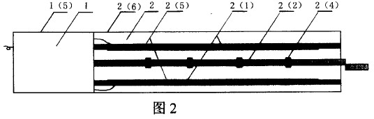
FIG. 2A is a cross-sectional side view of a first embodiment of a PEF treatment device having cylindrical electrodes and a cylindrical insulator.

FIG. 2B is a sectional view taken along section line 2B--2B of FIG. 2A.

FIG. 3A is a cross-sectional side view of a second embodiment of a PEF treatment device having non-cylindrical electrodes and a non-cylindrical insulator.

FIG. 3B is a sectional view taken along section line 3B--3B of FIG. 3A.

FIG. 4 is a cross-sectional side view of a third embodiment of a PEF treatment device having tapered electrode flow chambers.

FIG. 5 is a cross-sectional side view of a fourth embodiment of a PEF treatment device having three electrodes and two insulators.

FIG. 6 is a cross-sectional side view of a fifth embodiment of a PEF treatment device having two electrodes of different cross-sectional geometry.

FIG. 7 is a cross-sectional side view of a sixth embodiment of a PEF treatment device.

FIG. 8A is a cross-sectional side view of a seventh embodiment of a PEF treatment device having conducting and insulating members concentrically located within flow chambers.
FIG. 8B is a sectional view taken along section line 8B--8B of FIG. 8A,


FIG. 9 is a graph illustrating the effect of pulse duration time on the inactivation of bacterial spores at the same energy input.

FIG. 10 is a graph illustrating the effect of bacterial spore inactivation as the pulsed electric field frequency is varied,

FIG. 11 is a graph illustrating the effect of temperature variation on bacterial spore inactivation,

FIG. 12 is a graph illustrating the effect on bacterial spore inactivation in two treatment mediums as the treatment time is varied,

FIG. 13 is a bar graph illustrating the effect on bacterial spore inactivation at different electric field intensities as the treatment time is varied,

DETAILED DESCRIPTION OF ILLUSTRATED EMBODIMENT
PEF Treatment System Structure
A pulsed electric field (PEF) treatment system is illustrated in FIG. 1. The system includes a balance tank 101, a de-oxygenator 102, a pulseless pump 104, heat exchangers 105A, B and C, PEF treatment devices 106A, B and C, a high voltage pulse generator 107 and an aseptic packaging device 108. The balance tank 101 holds the liquid product to be treated by the PEF system. The liquid product may be a wide range of products, including edible food products having a viscosity or extrusion capacity such that the food product may be forced into a flow through a treatment chamber. Other liquid products include extrudible products such as doughs or meat emulsions, fluid products such as beverages, fluid dairy products, gravies, sauces and soups, and food particulate containing food slurries such as stews, and food particulate containing soups, and cooked or uncooked vegetable or grain slurries. Moreover, the liquid food product may include nutriceutic, cosmetics and pharmaceutical products. The balance tank 101 is in physical communication with the de-oxygenator 102. The de-oxygenator 102 serves to remove dissolved gasses and/or product bubbles which might adversely affect the development of a substantially uniform electric field in the liquid product as it is treated in PEF treatment devices 106A, B and C.
The pulseless pump 104 is in physical communication with the de-oxygenator unit 102. The pulseless pump 104 provides the PEF treatment system with a flow of liquid product at a constant velocity to ensure uniform treatment. The pulseless pump 104 is further in physical communication with heat exchanger 105A and PEF treatment device 106A.
The heat exchangers 105A, B and C are in physical communication with PEF treatment devices 106A, B and C as shown in FIG. 1. While FIG. 1 illustrates the use of three heat exchangers interdigitized between three PEF treatment devices, different combinations involving more or less heat exchangers and PEF treatment devices are possible. For example, the PEF treatment system may include only one heat exchanger and one PEF treatment device. Generally, the number of heat exchangers and the number of PEF treatment devices will depend on the system design and treatment objectives. The heat exchangers 105A, B and C primarily serve as temperature regulators for the PEF treatment system. As shown in FIG. 1, the liquid product's temperature is first regulated by a heat exchanger before entering a PEF treatment device for sterilization or bacterial inactivation.
Still referring to FIG. 1, the high voltage pulse generator 107 is in circuit communication with each PEF treatment device. The high voltage pulse generator 107 provides PEF treatment devices with a high voltage wave form having variable voltage levels, frequency ranges and pulse duration times.
The last PEF treatment device (106C) is in physical communication with the aseptic packaging device 108. The aseptic packaging device 108 serves to aseptically pack and seal the liquid product in a sterile environment. One such commercially available aseptic packaging device is the Benco LaborPack/2 Aseptic Packaging Machine.
PEF Treatment Device Structure
Referring now to FIG. 2A, a cross-sectional side view of an embodiment of a pulsed electric field treatment device 200 is shown. The PEF treatment device 200 includes a first electrode 201 and a second electrode 203 and an insulator 202. First electrode 201 includes an electrode flow chamber 207 for making electrical contact with the liquid product and for allowing the liquid product to flow through the PEF treatment device 200. Similarly, electrode 203 includes an electrode flow chamber 208 for making electrical contact with the food product and for allowing the food product to flow out of the PEF treatment device 200. The electrode flow chambers 207 and 208 each include inlet and outlet apertures at 213 and 209, and at 211 and 215 respectively.
The insulator 202 is in physical communication with the first electrode 201 and the second electrode 203. The insulator 202 includes an insulator flow chamber 206 for allowing the flow of liquid product from the first electrode 201 to the second electrode 203. The insulator flow chamber 206 is in physical communication with the first electrode flow chamber 207 and the second electrode flow chamber 208 and includes an inlet and outlet aperture at 209 and 211 respectively. As shown in FIG. 2A, the first electrode 201, second electrode 203, insulator 202, first electrode flow chamber 207, insulator flow chamber 206, and second electrode flow chamber 208 are formed and configured such that the electrode flow chambers 207 and 208 and the insulator flow chamber 206 form a single tubular flow chamber through the PEF treatment device. The insulator flow chamber inlet aperture and the first electrode flow chamber outlet aperture are positioned adjacent to each other and have substantially similar cross- sectional geometry. Similarly, the insulator flow chamber outlet aperture and the second electrode flow chamber inlet aperture are positioned adjacent to each other and have substantially similar cross-sectional geometry. The phrase "substantially similar" is hereinafter used to express the concept that one may depart from the overall inlet and outlet aperture dimensions and shape and still maintain an overall degree so similarity in geometry and/or functionality. For example, inlet and outlet physical dimensions and shapes need not be identical, that is, the insulator flow chamber inlet or outlet apertures may be slightly larger or smaller than the electrode flow chamber outlet or inlet apertures, or vice-versa. Moreover, the electrode flow chamber inlet or outlet aperture may be elliptical while the insulator flow chamber outlet or inlet aperture may be circular, or vice-versa. Therefore, it should be apparent that an electrode flow chamber's inlet and/or outlet apertures and the insulator flow chamber's inlet and/or outlet apertures may have different dimensions and shapes and still maintain substantially similar cross-sectional geometries.
Referring now to FIG. 2B, a sectional view taken along a section line 2B--2B of FIG. 2A of PEF treatment device 200 is shown. The insulator 202 further includes an outer cylindrical insulator surface 214 and an inner cylindrical insulator surface at boundary 210. The electrode 201 includes an outer cylindrical electrode surface at boundary 210 that is in physical communication with the inner cylindrical insulator surface, also located at boundary 210. The electrode 201 further includes an inner cylindrical electrode surface 212 that forms the electrode flow chamber 207.
Referring now to FIG. 3A, a cross-sectional side view of a second embodiment of a pulsed electric field treatment device 300 is shown. As evident from FIG. 2A, PEF treatment device 300 and PEF treatment device 200 have substantially similar cross-sectional side views. In particular, the PEF treatment device 300 includes a first electrode 301, a second electrode 303 and an insulator 302. First electrode 301 includes an electrode flow chamber 307 for making electrical contact with the liquid product and for allowing the liquid product to flow through the PEF treatment device 300. Similarly, the electrode 303 includes an electrode flow chamber 308 for making electrical contact with the food product and for allowing the food product to flow out of the PEF treatment device 300. The electrode flow chambers 307 and 308 each include inlet and outlet apertures.
The insulator 302 is in physical communication with the first electrode 301 and the second electrode 303. The insulator 302 includes an insulator flow chamber 306 for allowing the flow of liquid product from the first electrode 301 to the second electrode 303. The insulator flow chamber 306 is in physical communication with the first electrode flow chamber 307 and the second electrode flow chamber 308 and includes an inlet and an outlet aperture. As shown in FIG. 3A, the first electrode 301, second electrode 303, insulator 302, first electrode flow chamber 307, insulator flow chamber 306, and second electrode chamber 308 are formed and configured such that the electrode flow chambers 307 and 308 and the insulator flow chamber 306 form a single tubular flow chamber through the PEF treatment device 300. The insulator flow chamber inlet aperture and the first electrode flow chamber outlet aperture are positioned adjacent to each other and have substantially similar cross-sectional geometry. Similarly, the insulator flow chamber outlet aperture and the second electrode flow chamber inlet aperture are positioned adjacent to each other and have substantially similar cross-sectional geometry. In all embodiments hereinafter, the above insulator flow chamber inlet and outlet aperture configuration with electrode flow chamber inlet and outlet apertures shall be generally applicable.
Referring now to FIG. 3B, a sectional view taken along a section line 3B--3B of FIG. 3A of PEF treatment device 300 is shown. The insulator 302 further includes an outer rectangular surface 314 and an inner rectangular surface having rounded ends at boundary 310. The first electrode 301 also includes an outer rectangular surface with rounded ends at boundary 310 and further is in physical communication with the inner rectangular insulator surface, also located at boundary 310. The first electrode 301 further includes an inner rectangular surface 312 with rounded ends 316 and 318. The inner rectangular surface 312 forms the electrode flow chamber 307. It should be noted that from FIGS. 2B and 3B, the sectional geometry of a PEF treatment device may take on various geometries based on design factors such as the nature of the liquid product (viscosity, particulate, electrical resistivity, etc.), liquid product flow rate, applied electric field strength, etc. Therefore, the PEF treatment device cross-sectional geometries may range from tubular or cylindrical cross-sections with tubular or cylindrical flow chambers, as shown in FIG. 2B, to rectangular cross-sections with rectangular flow chambers, as shown in FIG. 3B. Other possible cross-sectional geometries for the PEF treatment device and the flow chambers include uniform and non-uniform geometries and various elliptical geometries.
Illustrated in FIG. 4 is a cross-sectional side view of a third embodiment of a pulsed electric field treatment device 400, having tapered electrode flow chambers 407 and 408. The PEF treatment device 400 includes a first electrode 401 and a second electrode 403, and an insulator 402. The first electrode 401 includes an electrode flow chamber 407 for making electrical contact with the liquid product and for allowing the liquid product to flow through the PEF treatment device 400. The electrode flow chamber 407 includes tapered surfaces 424 and 426 and inlet and outlet apertures. Similarly, electrode 403 includes an electrode flow chamber 408 for making electrical contact with the liquid product and for allowing the liquid product to flow out of the PEF treatment device 400. Moreover, electrode flow chamber 408 includes tapered surfaces 420 and 422 and inlet and outlet apertures. The tapered surfaces 424 and 426 may be elements of various cross-sectional designs of the electrode flow chamber 407. Similarly, tapered surfaces 420 and 422 may be elements of various cross-sectional designs of electrode flow chamber 408. For example, electrode flow chambers 407 and 408 may include conical sectional geometries which include the tapered surfaces 424, 426, 420 and 422. Furthermore, the electrode flow chambers 407 and 408 may have rectangular or elliptical sectional geometries with decreasing areas that include tapered surfaces 424, 426, 420 and 422. Consequently, electrode flow chambers 407 and 408 can have any geometrically tapered sectional or cross-sectional geometry that is suitable for the system design specifications.
Illustrated in FIG. 5 is a cross-sectional side view of a fourth embodiment of a pulsed electric field treatment device 500, having three electrodes and two insulators. The PEF treatment device 500 includes a first electrode 501, a second electrode 503, a third electrode 505, a first insulator 502 and a second insulator 504. The first electrode 501 includes an electrode flow chamber 507 for making electrical contact with the liquid product and for allowing the liquid product to flow through the PEF treatment device 500. Similarly, second and third electrodes 503 and 505 include electrode flow chambers 508 and 510 for making electrical contact with the liquid product and for allowing the liquid product to flow through and out of the PEF treatment device 500. The first insulator 502 is in physical communication with the first electrode 501 and second electrode 503. The first insulator 502 includes an insulator flow chamber 506 for allowing the flow of liquid product from the first electrode 501 to the second electrode 503. Similarly, the second insulator 504 is in physical communication with the second electrode 503 and the third electrode 505. The second insulator 504 also includes an insulator flow chamber 509 for allowing the flow of liquid product from the second electrode 503 to the third electrode 505. The insulator flow chamber 506 is in physical communication with the first electrode flow chamber 507 and the second electrode flow chamber 508 and is positioned therebetween. Similarly, insulator flow chamber 509 is in physical communication with the second electrode flow chamber 508 and the third electrode flow chamber 510, and is positioned therebetween. As shown in FIG. 5, the electrode flow chambers 507, 508 and 510, and insulator flow chambers 506 and 509 are formed and configured such that the electrode flow chambers and the insulator flow chambers form a single flow chamber through the PEF treatment device 500.
Illustrated in FIG. 6 is a cross-sectional side view of a fifth embodiment of a pulsed electrical field treatment device 600, having two electrodes of different cross-sectional geometries. The PEF treatment device 600 includes a first electrode 601 and a second electrode 603 and an insulator 602. The first electrode 601 includes a tapered electrode flow chamber 607 for making electrical contact with the liquid product and for allowing the liquid product to flow through the PEF treatment device 600. The tapered electrode flow chamber 607 includes tapered surfaces 624 and 626. As was described for electrode flow chamber 407 of FIG. 4, electrode flow chamber 607 can employ a variety of sectional and cross-sectional geometries based on the design specifications of the PEF treatment system.
The insulator 602 is in physical communication with the first electrode 601 and the second electrode 603. The insulator 602 includes an insulator flow chamber 606 for allowing the flow of liquid product from the first electrode 601 to the second electrode 603. The insulator flow chamber 606 is in physical communication with the first electrode flow chamber 607 and the second electrode flow chamber 608 and is positioned therebetween. As shown in FIG. 6, the electrode flow chambers 607 and 608 and the insulator flow chamber 606 are configured such that a single flow chamber is formed through the PEF treatment device 600.
Illustrated in FIG. 7 is a cross-sectional side view of a sixth embodiment of a pulsed electric field treatment device 700 having removable components. The PEF treatment device 700 includes a first and second electrode 701 and 703. The first electrode 701 includes an electrode flow chamber 707 for making electrical contact with the liquid product and for allowing the flow of liquid product into PEF treatment device 700. Similarly, the second electrode 703 includes an electrode flow chamber 708 for making electrical contact with the liquid product and from allowing the flow of liquid product to exit the PEF treatment device 700. The PEF treatment device 700 further includes a first insulator 702 and a second insulator 710. The first and second insulators 702 and 710 are in physical communication with each other and are connected via threading surfaces 718 and 720. The first insulator 702 includes inner threads, and the second insulator 710 includes outer threads such that the insulators 702 and 710 may be tightly threaded together.
Still referring to FIG. 7, the PEF treatment device 700 further includes an insulation cushion 712 and a first and second insulation washer 714 and 716. The insulation cushion 712 is in physical communication with the first and second electrodes 701 and 703, the first and second insulators 702 and 710, and the first and second insulation washers 714 and 716. Furthermore, insulation cushion 712 includes an insulator flow chamber 706 for allowing the flow of liquid product from the first electrode 701 to the second electrode 703. The configuration of the various components shown in FIG. 7 of PEF treatment device 700 are all concentric so that PEF treatment device 700 may be quickly assembled or disassembled via a twisting or turning motion due to the threaded interconnection of first insulator 702 and second insulator 710. This provides PEF treatment device 700 with the major advantages of low cost and easy maintenance. Additionally, PEF treatment device 700 has the advantage of allowing easy removal and replacement of the insulator cushion 712 and the insulator flow chamber 706.
Referring now to FIG. 8A, a cross-sectional side view of a seventh embodiment of a pulsed electric field treatment device 800 is shown. The PEF treatment device 800 includes a first electrode 801 and a second electrode 803 and a first insulator 802. First electrode 801 includes an electrode flow chamber 807 for making electrical contact with the liquid product and for allowing the liquid product to flow through the PEF treatment device 800. Similarly, electrode 803 includes an electrode flow chamber 808 for making electrical contact with the food product and for allowing the food product to flow out of the PEF treatment device 800. The first electrode 801 is in physical and/or circuit communication with a first conducting insert member 810 and the second electrode 803 is, similarly, in physical and/or circuit communication with a second conducting insert member 811. The first and second conducting members 810 and 811 are concentric with first and second electrodes 801 and 803 and are concentrically located within electrode flow chambers 807 and 808. Moreover, the first and second electrodes 801 and 803 may include an integrated construction that includes insert members 810 and 811 respectively. In the illustrated embodiment, the conducting insert members 810 and 811 have rod-like geometries.
The insulator 802 is in physical communication with the first electrode 801 and the second electrode 803. The insulator 802 includes an insulator flow chamber 806 for allowing the flow of liquid product from the first electrode 801 to the second electrode 803. The insulator flow chamber 806 is in physical communication with the first electrode flow chamber 807 and the second electrode flow chamber 808. An insulator insert member 809 is concentrically locted within insulator flow chamber 806 and is in physical communication with first and second conducting insert members 810 and 811. As shown in FIG. 8A, the first electrode flow chamber 807, insulator flow chamber 806, second electrode flow chamber 808, conducting insert members 810 and 811 and insulating insert member 809 are formed and configured such that the electrode flow chambers 807 and 808 and the insulator flow chamber 806 form a single tubular flow chamber through the PEF treatment device.
Referring now to FIG. 8B, a sectional view taken along a section line 8B--8B of FIG. 8A of PEF treatment device 800 is shown. The insulator 802 further includes an outer cylindrical insulator surface 814 and an inner cylindrical insulator surface at boundary 816. The electrode 801 includes an outer cylindrical electrode surface at boundary 816 that is in physical communication with the inner cylindrical insulator surface, also located at boundary 816. The electrode 801 further includes an inner cylindrical electrode surface 812 that forms the electrode flow chamber 807. The first conducting insert member 810 includes an outer cylindrical member 818 and is concentrically positioned within electrode flow chamber 807 to provide the flow chambers 807, 806, and 808 with improved liquid product flow characteristics (i.e. uniformity of liquid velocity), where such improved liquid flow characteristics are desirable.
In all of the illustrated embodiments, the electrodes comprise food-grade stainless steel. However, any other food-grade, electrically conducting material may be substituted in the above embodiments for the stainless steel. The various insulation components of the presently described embodiments are comprised of polycarbonate. However, the insulation components may be any electrically insulating material such as ceramics, glass or plastics.
Operation of The PEF Treatment Devices
To recall, the PEF treatment process applies an electric field voltage across two electrodes where a liquid product, such as a food product, exists between the electrodes. Because most liquid food products are primarily composed of water and nutrients, a corresponding electric field is induced in the food product. A bactericidal effect, commonly called the Dielectric Rupture Theory, arises due to this induced electric field in the liquid food product. According to the Dielectric Rupture Theory, PEF treatment reduces the activity of bacteria and other micro-organisms by damaging the bacterial or micro-organism cell structure. The applied electric field induces an electric potential across the membrane of a living cell, which, in turn, causes an electrostatic charge separation in the cell membrane and results in pore formation in weak areas of the cell membrane. The pore formation and cell membrane damage have a lethal effect on the bacteria or micro-organism. The operation of PEF treatment device 200 shown in FIGS. 2A and 2B will now be presently described in detail with respect to the inactivation of the Bacillus subtilis species of bacterial spore and with the understanding that the operational description is equally applicable to PEF treatment devices 300-800 shown in FIGS. 3A-8B.
Referring now to FIGS. 1, 2A and 2B, electrode 203 is in circuit communication with a high voltage terminal of the high voltage pulse generator 107 and electrode 201 is in circuit communication with a ground network. Therefore, when a high voltage pulse signal is applied across electrodes 203 and 201, an electric field is formed in electrode flow chambers 207 and 208, and insulator flow chamber 206. Furthermore, due to the physical configuration of electrodes 201 and 203 and insulator 202, the electric field strength will be strongest in insulator flow chamber 206, and will have a vector direction pointing from electrode 203 to electrode 201. Therefore, as liquid product passes through electrode flow chamber 207 to insulator flow chamber 206 and through electrode flow chamber 208, it is subjected to an applied electric field that is concentrated in insulator flow chamber 206. Accordingly, the liquid product in insulator flow chamber 206 is subjected to the concentrated applied electric field and because the liquid product is primarily composed of water and nutrients, the concentrated applied electric field will be present within the liquid product. Therefore, the bactericidal effect of the PEF treatment process of the present invention primarily occurs in the liquid product flowing through insulator flow chamber 206.
Illustrated in FIG. 9 is a graph showing the effect of pulse duration time on the inactivation of bacterial spores at a constant applied electric field. More particularly, FIG. 9 illustrates the inactivation of bacterial spores with pulse duration times of 1, 2, 4 and 6 microseconds and at frequencies of 3,000, 1,500, 750 and 500 Hz, respectively, and at an applied electric field strength of E=30 kV/cm and a temperature of T=36.degree. C. FIG. 9 indicates that, with the same energy input, when the pulse duration time is increased from 1 to 6 microseconds, the inactivation of spores increases. As shown in FIG. 8, ninety-two percent (92%) of the spores were inactivated with 6 microsecond pulse durations applied for 1,770 microseconds (i.e., 295 pulses). In FIG. 8, the frequency was decreased in correspondence to the increased pulse duration times so that a constant power input was maintained for comparison purposes. As evident from FIG. 8, the frequency of the applied electric field signal is a factor that affects the inactivation rate of the bacterial spores.
Illustrated in FIG. 10 is a graph showing the effect of bacterial spore inactivation as the pulsed electric field frequency is varied. More particularly, FIG. 10 illustrates the inactivation of bacterial spores at frequencies of 2,000, 3,000 and 4,000 Hz, with a pulse duration time of 3 microseconds and an applied electric field strength of E=30 kV/cm at a temperature of T=36.degree. C. Therefore, as the frequency increases, the number of pulses and total treatment time that the bacterial spores receive also increases. However, as shown in FIG. 10, the inactivation rate of bacterial spores decreases as the frequency increases. Since bacterial spores are hard, but structurally fragile, FIG. 10 indicates that there is an optimal PEF treatment frequency that may cause resonance of the bacterial spore structure. This resonance causes a loosening of the rigid bacterial spore structure such that the applied pulsed electric field can, in effect, punch through the spore structure and inactivate the spores.
Illustrated in FIG. 11 is a graph showing the effect of temperature variation on bacterial spore inactivation. Particularly, FIG. 11 illustrates the inactivation of bacterial spores at different treatment temperatures with an applied electric field strength of E=30 kV/cm at a frequency of f=1,500 Hz and a pulse duration time of .tau.=2 microseconds. The inactivation of bacterial spores was tested at 20.degree., 30.degree., 36.degree., 40 and 50.degree. C. The results shown in FIG. 11 illustrate that there is an optimum temperature of 36.degree. C. for inactivating bacterial spores by PEF treatment. FIG. 11 also illustrates that the inactivation rate of bacterial spores increases with the total PEF treatment time at 30.degree. and 36.degree. C. treatment temperatures, while the inactivation rate does not exhibit significant change after 540 microseconds of total treatment time at 20.degree., 40.degree. and 50.degree. C. treatment temperatures. These results indicate that at the optimum treatment temperature, more bacterial spores tend to germinate and to be inactivated as the treatment time is extended.
Referring now to FIG. 12, a graph illustrating the effect on bacterial spore inactivation in two treatment mediums as the treatment time is varied is shown. FIG. 12 shows the inactivation of bacterial spores in two treatment mediums: a 0.02% NaCl and a 0.02% NaCl+0.01% L-alanine. The PEF treatment parameters for FIG. 12 were an applied electric field strength of E=30 kV/cm, f=1,000 Hz, pulse duration time of .tau.=6 microseconds and a treatment temperature of T=36.degree. C., while two PEF treatment devices were used in series with an insulator flow chamber of 2 mm. L-alanine is considered as a germination agent for many strains of bacterial spores. As shown in FIG. 12, the inactivation rate of bacterial spores in the 0.02% NaCl treatment medium supplemented with the 0.01% L-alanine germination agent is higher than that of the 0.02% NaCl treatment medium without any germination agent. Also as shown in FIG. 12, for the first 120 microseconds of treatment time, there is very little difference between the inactivation rate of bacterial spores in the two treatment mediums. However, when the treatment time reaches 300 microseconds, the inactivation difference between the two mediums grows larger. These results indicate that more bacterial spores tend to germinate and be inactivated by PEF treatment as the treatment time is increased. Moreover, the results of FIG. 12 are consistent with the temperature results shown in FIG. 11.
Illustrated in FIG. 13 is a bar graph showing the effect on the inactivation of bacterial spores at different applied electric field intensities as the treatment time is varied. More particularly, FIG. 13 shows the effect on bacterial spore inactivation at three electric field levels: 30, 37 and 40 kV/cm, while maintaining the applied electric field frequency at 2,000 Hz and the pulse duration time at .tau.=3 microseconds and at a treatment temperature of T=36.degree. C. FIG. 13 indicates that as the electric field intensity increases, the inactivation of bacterial spores increases. More particularly, after the bacterial spores were exposed to an electric field strength of 40 kV/cm for 3.5 milliseconds, 98% of the bacterial spores were inactivated. Therefore, the results shown in FIG. 13 indicate that in order to obtain a greater inactivation of bacterial spores, higher electric field strengths may be applied.
Accordingly, more than 95% of Bacillus subtilis bacterial spores were inactivated by the continuous flow PEF treatment system of the present invention with frequency ranges from 500 Hz to 4,000 Hz and a pulse duration time from 1 microseconds to 6 microseconds. Moreover, the optimum PEF treatment temperature for Bacillus subtilis bacterial spores is 36.degree. C., and the presence of a germination agent, such as L-alanine, significantly enhances the PEF inactivation of the Bacillus subtilis bacterial spores. Furthermore, frequencies beyond 4000 Hz are possible. For example, frequencies from 4000 to 20,000 Hz may be employed depending on the system design parameters.
While the present invention has been illustrated by the description of embodiments thereof, and while the embodiments have been described in considerable detail, it is not the intention of application to restrict or in any way limit the scope of the appended claims to such detail. Additional advantages and modifications will readily appear to those skilled in the art. For example, the insulators, electrodes and liquid flow chambers may employ a variety of cross-sectional and sectional geometries, and the PEF treatment system operating parameters, such as applied electric field strength, treatment temperature and liquid product flow rates may be varied based on the nature of the liquid product to be treated, the micro-organism and/or bacterial to be inactivated. Therefore, the invention, in its broader aspects, is not limited to the specific details, the representative apparatus, and illustrative examples shown and described. Accordingly, departures may be made from such details without departing from the spirit or scope of the applicant's general inventive concept.
http://www.inventors-showcase.com/invention_of_the_week
Invention of the Week --
Quantum Wine Ager
The Quantum Ultrasonic wine and spirit ager is one of the most exciting inventions to come along in ages.
Anyone who enjoys wines and spirits will appreciate this amazing device.
Why pay hundreds for an aged single malt or vintage wine when, in the space of 30 minutes your drink will belie the price you paid...
Restaurants love this product for what it will do to their high profit margin house wines. Producers and distillers love it because their drinks taste vintage right out of the vat. And drinkers love it because the delicate aged taste is more accessible than ever before.
By changing the chemical balance of the alcohol esters, a few minutes in the wine ager can make a cheap bottle of wine taste like a mature vintage.
NON
INTRUSIVE: Your
bottle is not opened and nothing is added to the drink.
FAST TO
USE:
30-50 minutes is all thats needed.
ELEGANT STAINLESS STEEL DESIGN: Looks great in kitchens and
restaurants.
NO CONSUMABLES REQUIRED:
HANGOVERS GREATLY REDUCED:
LOW POWER CONSUMPTION:
Please send details to quantum@inventors-showcase.com for more info.
Quantum Wine Ager
Price: £349.95
AGING OF ALCOHOLIC BEVERAGE
JPS5668385
PURPOSE:An alcoholic beverage is irradiated with ultrasonic wave to accelerate the aging and maturing, thus producing good-quality alcoholic beverage. CONSTITUTION:An alcoholic baverage such as Japanese sake, whisky, wine, brandy or liquor is irradiated with ultrasonic wave of 16-60KHz. The aging by the irradiation with ultrasonic wave is though to be caused by accelerating reactions of oxidation, polymerization, condensation, etc., of alcohol, aldehydes, esters and olefins to form new complicated substances that develop good flavor and body.
JPH0380070
RIPENING APPARATUS
PURPOSE:To provide a ripening apparatus effective in accelerating the ripening of vinegar, etc., and composed of an electromagnetic wave antenna, an ultrasonic vibrator and a far infrared generation element placed on the inner wall of a tank or a pipe and a driving apparatus to drive the above devices in a continuous, intermittent or staggered mode. CONSTITUTION:Two or more devices selected from an electromagnetic wave antenna 3, an ultrasonic vibrator 4 and a far infrared generation element 5 are placed on the inner wall of a tank 1 and the devices are driven in continuous, intermittent or staggered mode with driving apparatuses 8, 9, 10. A ripening object such as rice wine or vinegar filled in the tank 1 is ripened in a short time by using the ripening apparatus having the above construction.
ULTRASONIC APPARATUS FOR MANUFACTURING GINSENG WINE
KR830000388
An ultrasonic appts. for manufg. Ginseng wine was described.A transducer(6) was installed in treating chamber(5) to be high density ultrasonic flux between A and B position. A mixing chamber(2) was adjacently positioned to a evaporating chamber(12) to circulate Ginseng wine by a pump(4). An exhaust pipe(13) and cooling chamber(14) were positioned in the upper part of the evaporating chamber, then sludges were removed in the storage chamber(15). Thus, 30 kg dried Ginseng and 157l 95% spirits were treated in 143 water for 6 hr to obtain Ginseng wine.
CN86200014
WINE-MAKING DEVICE BY MEANS OF ION-IMPLANTATION
The utility model discloses a wine making device by means of ion-implantation. Two hollow electrodes which are fixed by copper sheet and the end are mutual isolation are inserted the relative location of the sidewall of a treating groove. The other end of the copper sheet is connected with high voltage power supply through the switch of the sphere gap. When the utility model is used, the oxygen enters the centre hole through the electrodes, and the oxygen is ionized through high-pressure discharge when the aging wine flow through the treating groove, so the aging process of the wine is accelerated through the various effects, such as oxidation, liquid electricity, strong light and ultrasonic wave. The wine making device by means of ion-implantation has the advantage of compact structure. The speed and the effect of the aging wine is obviously better than the prior art.
JPH0795873
PRODUCTION OF WINE, BEER AND REFINED SAKE
PURPOSE:To provide a production method of wine, refined sake (japapese rice wine), etc., capable of promoting fermentation and production a fragrant product by irradiating weak ultrasonic wave on the fermentation material at a low temperature in a fermentation process. CONSTITUTION:Fermentation material is sealed in a jar-fermenter 1 and the material is fermented while the temperature of the material is controlled at <=15 deg.C by means of a temperature controlling device 6. Vibration energy is supplied to a piezoelectric transducer 3 from a vibration circuit 2 and weak ultrasonic wave is irradiated from the piezoelectric transducer 3 into the inside of the jar-fermenter 1 to accelerate the fermentation. In this process, owing to the irradiation of the weak ultrasonic wave to the fermentation material at a low temperature, the carbon dioxide is reduced to the saturated concentration of the temperature and the fermentation is stimulated. Fragrance components affecting favorable effect on the product are increased, and accordingly, a fragrant fermentation product can be produced.
JPS62269663
RIPENING APPARATUS
BG51814
Apparatus using ultrasound and replacing champagnisation of sparkling wine
FR2687409
HIGH EFFICIENCY ARTIFICIAL AGEING RIPENING DEVICE FOR WINE
Apparatus using ultrasound and replacing conventional apparatuses for champagnisation of sparkling wines. Hanging ramps on which the bottles are placed are loaded into the liquid in which the ultrasonic transducer or transducers is or are placed. An adjustable timer regulates the immersion time which is a few seconds in length. The lamps are driven by chains, discs, triangles or the like. The whole is connected to an electric geared motor. Loading takes place on one side, unloading on the other. Conventional champagnisation lasts several weeks. This apparatus reduces the time to less than 48 hours.
CN2116697
PRODUCTION OF WINE, BEER AND REFINED SAKE
The utility model relates to a high efficiency artificial ageing ripening device for wine. The utility model comprises a direct current electric source, an electrolyzing device for water and an ageing ripening appliance, wherein, the voltage of the direct current electric source is adjusted, the electrolyzing device for water is used for an electrolyzing groove which is provided with two groove chambers, and the ageing ripening appliance cause oxygen and hydrogen generated by the electrolysis of wine which is to be processed and water solution to play a role. Furthermore, the ageing ripening appliance comprises a housing and an air inlet pipe which are made of materials such as stainless steel, ceramic or glass, etc., the inner part of the ageing ripening appliance can also provided with an ultraviolet lamp, an adsorption material with a plurality of holes, a high-frequency coil, etc., and an ultrasonic device can also be arranged on the ageing ripening appliance.
SET FOR CONTINUOUS PRODUCTION OF CLEARED JUICES AND WINES
JPH078236
CN2183996
The utility model relates to a quickly wine brewing kettle, comprising a wine containing container. The utility model is characterized in that the utility model also has a set of supersonic wave and laser emitting circuits; an ultrasonic vibrator is arranged at the container wall; the emitting end of a laser emitting tube is connected with an optical fiber bundle, the tail end of the optical fiber bundle aims at the transparent dots or the pinholes of the container wall. The utility model has the advantages that the fermention and the catalysis of the wine can be accelerated, the brewing time can be shortened, and the wine can be made more palatable.
CN2213729
Ultra-sonic treating device for liquid
US5604297
Spirulina wine and preparing process thereof
CN1175632
CN2280716
IMPROVEMENT IN TASTE OF ALCOHOLIC BEVERAGE AND APPARATUS THEREFOR
The utility model relates to an explosion-proof multi-frequency-wave wine-ageing quickening device, which is provided with an explosion-isolated regulation and control box. A connection pipe is arranged on the explosion-isolated regulation and control box, and the other end of the connection pipe is provided with an explosion-isolated outer shell. An electronic circuit board, an ultrasonic transducer and a super high frequency coil are arranged in the explosion-isolated outer shell, and an electrical conducting wire is arranged in the connection pipe and connected with the explosion-isolated regulation and control box and the electronic circuit board in the explosion-isolated outer shell. The utility model can shorten the wine-ageing time, and has the advantages of compact structure, low manufacture cost, convenient use, etc.
JPH119257
PLANT FOR STABILIZATION OF JUICES AND WINES
CN2393883
WINE TREATMENT UNIT
JP2001186870
METHOD FOR PRODUCING RED WINE
PROBLEM TO BE SOLVED: To provide a wine treatment unit enabling wine flavor to be fully elicited in a short time at low cost. SOLUTION: This wine treatment unit is designed to continuously apply magnetism to a wine after vibrated, that is, has such a scheme that a wine in the tank 11 set on an ultrasonic vibrator 1 is subjected to ultrasonic vibration and then put to magnetism continuously using a magnetism application unit 3.
GB2365417
Portable wine device capable of removing harmful matter
CN2457163
Efficient wine-quality processing equipment
CN2522421
A clarification and fusion method for low degree distillation wine
An efficient wine-quality processing equipment uses comprehensive processing means of high- and low-frequency ultrasonic, ultraviolet light, constant magnetic magnetizer and so on to process wine (liquor, beer, colored wine; more than ten minutes are only needed to finish functions of eliminating impurities, increasing fragrance and catalyzing the brewing process; the brewing process is shortened to be between 1.5 years and 2 years. The equipment has quite wide applicability; according to needs of users, the equipment can be made into serial products of various specifications, which is suitable for large and small wineries; the equipment speeds up physical and chemical changes in the brewing process of a novel wine and has functions of ''eliminating impurities'', ''increasing fragrance'', and improving the taste of a novel wine; the equipment promotes the early maturity of a novel wine and greatly improves the quality of the novel wine.
JP2003289847
TREATMENT OF A PRODUCT TO REDUCE PHENOLIC BITTERNESS
WO03016459
Ultrasonic vibration magnetizing appliance for liquid
A process is disclosed for treating a product, which will usually be wine, which suffers from phenolic bitterness. The method consists of treating the product with an ultrasonic waveform, the waveform having a frequency of between 100 kHz and 1000 kHz and an intensity of between 1,2 W/cm squared and 100 W/cm sqared. Preferably the energy dose is between 1000 and 100000 Watt seconds per litre.
CN2597461
HYPERSONIC DEVICE
RU2298030
METHOD FOR PREPARING TRADITIONAL WINE USING PINE NEEDLES
NZ543156
An improved active wine barrel
NZ543157
Weak ultrasonic processor for liquid molecules
CN2747173
Wine aging method and system
US2006289350
Composite hastening aging equipment for wine
CN201167522
ultrasonic salt atomization method for accelerating spirit ageing
CN101223904
Supersonic wave apparatus for aged wine
CN101294129
Ultrasonic aging apparatus for wine
CN101422502
CN101760412
Wine comprehensive high-efficiency artificial strengthening physical aging method and manufacturing method of aging machine thereof
CN101760413
Cylindrical tube type acoustic liquid comprehensive function coprocessor
CN201380070
Device utilizing ultrasonic wave to promoting aging of white wine
CN101525572
An apparatus and method for the treatment of wine using ultrasonic cavitations
CN201445912
Fluid dynamic ultrasonic wine alcoholization device
CN101845379
Wine aging device
CN102051307
Fermented red date wine and brewing method thereof
CN102051312
Pipeline type ultrasonic treatment device for promoting ageing of wine
CN201901668
CN102059070
Hydraulic power/ ultrasonic coupling cavitation device
CN102181354
Method and apparatus for rapidly ageing wine
CN202343099
New technology for preparing ester spices by using fusel oil enzyme method and natural ester spices
CN102559784
Nano instant ripe wine maker
CN102433254
Novel technology for preparing natural ethyl-3-methyl-thiopropionate spice and ester spice prepared by novel technology
CN102787058
Method for brewing strawberry fruit wine by ultrasonic waves
CN103013735
Fermentation technology of honey wine
CN102994302
Preparation technology of cordyceps militaris grape wine
CN103053471
Ultrasonic treatment device and method for reducing ethyl carbamate in brewed wine
CN103103102
Brewing method for healthcare mulberry fruit wine
The invention discloses an ultrasonic treatment device for reducing ethyl carbamate (EC) in brewed wine. The ultrasonic treatment device comprises a rotational ultrasonic generator (11), wherein the lower part of the rotational ultrasonic generator has a structure which is in the shape of a Chinese character 'feng'; a motor (6) and a speed reducing box (7) are arranged above the rotational ultrasonic generator; the line incoming side of the motor is connected with a time controller (8); the whole device is vertically arranged in the center of a tank body (1); the tank body has a jacket-type two-layered wall structure; an interlayer between the two layers of walls is a water filling layer (10); a water outlet (12) with a valve is formed in the lower part of the outer wall; a water inlet (2) with a valve, a heating pipe jack (3) and a tank cover (5) are arranged on the upper part of the outer wall; a feeding port (9) with a valve is formed in the upper part of the tank cover; and a discharging port (13) with a valve is arranged on the lower part of the tank body. The reduction of EC is carried out in three steps: 1, preparation of pretreatment; 2, introduction of wine to be treated and adding of relevant materials; and 3, treatment of reducing the EC. By using the device and the method, 30-50 percent of EC in the wine can be reduced, and the health of drinkers is facilitated; and the device is low in energy consumption, low in cost and small in pollution.