Gennady SHIPOV
4-D Gyroscope Propulsion
4-D Gyroscope Propulsion
https://www.altpropulsion.com -
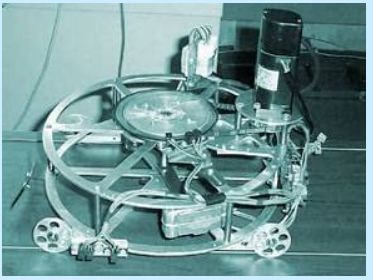
Dr. Gennady Shipov
demonstrates a model for a reactionless mechanical propulsion system developed by Russian engineer Vladimir Tolchin. The device, shown operating on a low-friction table covered with oil, clearly demonstrates directional thrust without ejecting reaction-mass based on a mechanism of gyroscopic precession.
Shipov writes, "For the experimental research of the 4-D gyroscope mechanics, its space-time precession, we created 11 models of the 4-D gyroscopes with the mechanical and electrical motor-breaks. Some of them have been operated by the computer software. We constructed the experimental bench-stand, consisting of the horizontal surface, the measuring system to register the translational coordinate and angular coordinate. The special software allowed us to calculate the linear and angular velocities in real time. The corresponding graphs have been monitored and observed during the experiments.
We have continued the experiments with Tolchin's mechanical devices and discovered that they deviated from Newton mechanics, when the center of mass had been affected by uncompensated forces of inertia, causing the phenomenon of space-time precession. We have observed that the phenomenon of space-time precession of four-dimensional gyroscope allows us to control its inertial mass. In the near future it will allow the creation of the Universal Propulsion System, which will be able to move in all forms of media: on earth, on water, under water, in air and in space. The 4-D Engine, with a hermetically sealed body, using space-time precession, will have quite a number of advantages and benefits, compared to any other engine: it will be ecologically clean, economic and universal. It should gradually replace the existing engines in many branches of contemporary technologies."

https://blog.go-here.nl/5550
Gennady Shipov Reactionless Drive
In this 20-second follow-up clip, Dr. Gennady Shipov elaborates on the concept of a "Universal Propulsion System" by demonstrating a device created by Russian engineer Vladimir Tolchin in a variety of mediums. The drive demonstrates thrust in a pendulum experiment, on a low-friction roller, and in a water environment...
Shipov writes, "This additional video clip consists of three parts: The first part shows a small inertial propulsor which is placed inside of a toy boat. The energy source is an electric capacitor. To exclude forces of friction, the boat is suspended on strings and slung beneath a rolling carriage. The carriage sits above on horizontal rails.
This experiment was proposed by a former pupil of Luis De Broglie, the French physicist J.P. Vigier at our meeting in San Francisco in 2000. Vigier noted that if the carriage moves, then it's necessary to rewrite the textbooks on basic mechanics. As it is possible to see from film the carriage does indeed move.
http://www.americanantigravity.com/articles/494/1/Shipov-Reactionless-Drive-Part-2/Page1.html
Shipov Reactionless Drive Part 2
http://shipov.com/
4D Warp Engine
Advantages of this type of propulsion include:
The ability to instantly change direction and speed
No breaks in the motion and no starter required
Movement is due to the control of the local properties of the space-time continuum
Movement occurs without reaction to friction or mass
Movement is more efficient than with conventional vehicles
Able to move in any media (on land or water, under water, in the air or space)
Less fuel is used, an important consideration for long distance space travel
Increase in energy efficiency (jet engine 2-10% vs. 4-D warp engine 40-60%)
Increased speed and traveling distance
Less harmful impact on the environment
Decreased overall weight of the transportation system
https://www.researchgate.net/profile/Shipov-Gennady
Shipov Gennady
Institute of Physical Vacuum Theory Department
http://einsteinandtesla.com/files/200506_news09.pdf
Dr. Gennady Shipov on Torsion Physics & Inertial Propulsion By Tim Ventura, April 18th, 2006
( PDF )
Last month, Dr. Gennady Shipov unveiled a new inertial propulsion drive developed by Russian inventor Vladimir Tolchin, adding to a growing body of Inertial Propulsion & Torsion-Physics research revisiting the basics of mechanical off-center rotators. He joins us to talk about several of the leading contenders in Russian inertial-drive technology, including a device by Valery Menshikov scheduled for testing this year by the Russian Space Agency
https://www.youtube.com/watch?v=u9-wdV32hos
Gennady Shipov's Inertial Propulsion Drive
http://video.google.com/videoplay?docid=7189261369558468761
Gennady Shipov Propulsion Demonstration (2) - Google Video
http://video.google.com/videoplay?docid=3061733767264623477
Gennady Shipov Propulsion Demonstration (1) - Google Video
https://www.youtube.com/watch?v=5UQKxRI_TiA
Dr. Gennady Shipov: New Scientific Paradigm and Breakthrough
( PDF )
Dr. Shipov is Director of the Science Center for Physics of Vacuum in Moscow State University and Director, Chief Researcher of UVITOR (Russia and Thailand), and honorary advisor to the Thai-Russian Association of Technology and Economic Development. In 1988 Gennady Shipov completed the challenging quest: Program of Universal Relativity and Theory of Physical Vacuum. Professor Shipov found the Vacuum Equations, representing a set of Geometrized Heisenberg, Einstein and Yang-Mills equations.
https://www.youtube.com/watch?v=-gnrI-VCcqg
Dr Gennady Shipov - Physical Vacuum, Torsion Fields, Quantum Mechanics and Tesla's Experiments
Communication Based on Quantum Entanglement
V. Zamsha, et al.
( PDF )
https://gennady-shipov.livejournal.com/2089.html?
G.I.Shipov Torsion Fields Fraud
(Taken from: Akimov-Shipov Torsion Fields Fraud)
In 1993, G.I. Shipov published a book "Theory of Physical Vacuum" wherein he described "Akimov's torsion generators and torsion technologies" (with pictures). Second edition of the book appeared in 1997, and in 1998 the third edition ("new and improved", "now in English") was published, whereafter the Russian Academy of Sciences organized the Commission Against Falsification of Scientific Research and conducted a scientific examination of the Shipov book. Results of the examination were published, in 2000, in the Russian Physics-Uspekhi Journal (vol. 3, 2000). Academician of RAS Dr. Valery Rubakov, who is a member of the RAS Commission, wrote a review on G.I. Shipov's book. In the review, Dr. V.A. Rubakov conclusively demonstrates that the Shipov book abounds with mathematical errors and false statements. In the end of his review, Dr. Valery Rubakov writes: "The book by G.I. Shipov might not have deserved a review in Physics-Uspekhi if it were not for the following circumstances. G.I. Shipov's "theory" is being actively propagandized by its author and his collaborators... And that is, undoubtedly, to the detriment of science and education... The possibility of existence of torsion fields have long been debated in scientific literature. But if such fields do exist, their interaction with matter must be extremely weak... Existing experimental and astrophysical data excludes the posibility to generate or register torsion fields with devices like "Akimov's torsion generators" described in the book by G.I. Shipov."
The device is a four-dimensional gyroscope with self-action, that demonstrates the controlled connection between translational and rotational inertia, which makes the center of masses to move translationally as a result of the preformed " internal impact". Such impact is achieved by the sharp change of the rotational energy of the system, meanwhile the device performs the principally new type of motion - shifting the center of masses effected by the internal non-compensated inertial forces. For the proof of the principally new type of motion in classical mechanics the device is equipped with a scientific research complex, which allows to observe the motion of the center of. masses effected by the inertial forces, as well as to compare the theoretical results with the experimental data.
BACKGROUND OF THE INVENTION
1. Field of the Invention
[0001] Herewith is claimed the invention of the device, the center of the masses of which is moved by the non-compensated inertial forces. The device is based on the principle of the four-dimensional gyroscope, which demonstrates the violation of the momentum conservation law during the absolute elastic collision. This violation happens due to the connection between the translational and rotational inertia. The self-action four-dimensional gyroscope is based on the device creating the guided change of the rotational inertia that moves its center of masses.
2. Description of the Prior Art
[0002] All the contemporary Field theory from Newton's gravitation theory and up to Einstein's general relativity theory was developing as a theory of the translational relativity. In such theories the spac is formed by the manifold of the translational coordinates, dealing with the translational motion of masses.
[0003] For the description of the translational motions of the free falling-lifts in the gravitational field A. Einstein has introduced the locally accelerated systems of the first kind, where the local gravitational force is compensated by the inertial force. That is why in Einstein's theory the inertial forces manifest themselves as real forces according to the 3<rd>law of Newton's mechanics. In the contemporary classic mechanics the inertial forces are not acting according to the 3<rd>law of New-ton's mechanics, because it is not possible to indicate the body which they are applied to.
[0004] In order to resolve the mentioned above contradiction the author had developed the torsion theory of the inertial forces ("The Theory of Physical Vacuum" Moscow, ST-Center, 1998). According to the new theory the complete description of the inertial forces requires the extension of the general relativity theory by adding the rotational relativity. The rotational relativity has required the introduction of the 10-dimensional coordinates space, where there are 4 translational coordinatesx, y, z, x<0>= ctand 6 rotational coordinates ?1, ?2,?3, ?1,?2, ?3. Besides that the angles ?1,?2,?3describe the space rotation of the matter and there are 3 "rotational" inertial forces connected with the changes of those coordinates, such as:
1) Centrifugal inertia force:
Image available on "Original document"
2) Coriolis force
3) Inertial force, caused by the rotational irregularity
as well as the angles ?1 , ?2 , ?3 denote the rotation of the matter in the space- time planesct - x ,ct - y andct - z, which cause the appearance of the translational inertial force
Unlike the Einstein's theory the new theory allows to investigate the free falling lifts rotating around a certain axis, where the inertial forces are acting locally, caused by rotation. Such forces are in action even though the gravitational field is absent and herewith we can discover the new class of the accelerated reference frames - the locally accelerated inertial reference frames of the second type. Such reference frames appear when the center of masses is effected by the inertial forces, which are compensating each other. The space of the events of the reference frames of the second kind has the structure of absolute parallelism, which has got both curvature and torsion. In general such space is not homogeneous and isotropic, that is why we observe the violation of the conservation laws, which are effective in the ordinary Euclidean dimension.
[0005] The four dimensional gyroscope is a typical sample of the accelerated local inertial reference systems of the second type and there are three inertial forces affecting its center of masses
and compensating each other. In this equation
- acceleration of the center of the masses of the gyroscope is equal to zero, that means that it moves with the uniformly or is at rest relatively to inertial reference frame. Nevertheless the reference frame, connected with its center of masses is accelerated because the inertial forces are acting though compensating each other. Thus we can state that in the above adduced equation the inertial forces satisfy the 3<rd>law of Newton mechanics and perform as real forces, by guiding of which we can change the velocity of the center of masses without using the external forces. The four-dimensional gyroscope with self-action is the device , which demonstrates the transportation of its own center of masses after the effect of the artificially created internal forces in it.
SUMMARY OF THE INVENTION
[0006] The invention of the four - dimensional gyroscope with self-action is claimed. The effect of self-action is achieved due to the utilization of the created and controlled inertial forces inside the device, which enables the motion of its center of the masses in spite of the absence of the action of the external forces.
In order to carry out the experimental research and to prove the correctness of this statement the four-dimensional gyroscope with self-action was constructed as well as the research center was established which allowed the following:
To prove experimentally the fact that the friction forces are not involved into the motion of the center of masses of the device.
To obtain the kinematical characteristics during the motion of the device as follows:
1) coordinatex (t ) of massesM ;
2) coordinatexc (t ) of the center of masses;
3) the angle of rotation? (t ).
With the help of the software to calculate:
1) velocity ?(t ) of massesM ;
2) velocity?c (t ) of the center of masses;
3) angular velocity? (t );
4) accelerationA (t ) of massesM ;
5) accelerationAc (t ) of the center of masses;
6) angular accelerationK (t ).
To demonstrate the movement of the device on the pendulum;
To demonstrate experiment Vijer, when the suspended device creates the draft and pools a cart.
BRIEF DESCRIPTION OF THE DRAWINGS
Ha FIG. 1 presents the view of the four-dimensional gyroscope, measuring blocks, motor-break, accelerating spring and supporting wheels.
Ha FIG.2 presents the top-view with small massesm positioned symmetrically along the longitudinal axis of symmetry x and accelerating spring
Ha FIG.3 presents the below view with the wheels, registering equipment and the elements of the motor-break.
DESCRIPTIONS OF THE PREFERED EMBODIMENTS
[0008] FIG.1 represents the general view of the device - the four - dimensional gyroscope with self-action The lower part 1 and the upper part 2 of its body are made from aluminum and connected with the steel studs 14. The central shaft 3 is equipped with a differential 5, which rotates synchronously small masses 4 in the different directions. The technological handle 12 starts the rotation. When the small masses arrive at the angle 300 ,the small spring 18 affects the cam 19 with the help of the lath 17, thus accelerating the rotation of the small masses 4. When the angle of the rotation arrives at 330 , the accelerating spring acts, increasing the angular velocity of rotation up to the angle of 360 . Beginning from the angle of 0 and up to the angle of 150 the small masses are in the free inertial rotation (self-action is absent). When the angular momentum will be 150 the cam 19 collides with the lath 17 , that stretches the spring 18 . As a result the angular momentum of the rotation of the small masses is decreasing.
[0009] The parameters of the angular of the rotation ?(t) during the motion of the four - dimensional gyroscope with self-action are being registered with the help of the polar ruler 8 and the photo-elements 9. The photo-elements 10 are synchronously registering the parameters of coordinatesx(t). The data are sent from the photo-elements to the computer for the further investigation. The specially developed software allows to monitor the basic kinematical parameters of the device during its motion in real time.
The device is a four-dimensional gyroscope, demonstrating the connection between the translational and the rotational inertia, which leads to the violation of the Momentum Conservation Law of the center of masses during its absolute elastic collision with the wall. For the proof of the violation of one of the basic Laws of Classic Mechanics the device is equipped with the scientific-research complex, that allows to observe double, triple, etc collisions of the four-dimensional gyroscope, as well as to perform comparison of the theoretical calculations with the experimental data.
BACKGROUND OF THE INVENTION
1.Field of the invention.
[0001] Herewith it is stated the invention of the device, which demonstrates the violation of the momentum conservation law of the center of masses of the Mechanical system. This violation is happening due to the existing connection inside the device between the translational and rotational inertia. In four dimensional space of the theory of special relativity the translational acceleration is viewed as rotation in space-time planes, that is why the invented device was named as "four-dimensional gyroscope ".
2.Description of the Prior Art.
[0002] The classical mechanics knows two types of the inerti a of the object: translational inertia of Galileo-Newton's, the analytical expression of which is the first law of Newton's mechanicsma ?
= 0 (wherem- mass and a ?
- acceleration of the object) and the rotational inertia of Newton -Euler's the analytical expression of which is the first law of Newton -Euler's mechanicsJ?? ?
=0 (whereJ- moment of inertia and ?? ?
- angular velocity of the rotation of the object). In the classical mechanics it was accepted that these two types of inertia are exist additively and have no connection between them. The present invention provides four-dimensional gyroscope, which establishes such connection both in the theory and in the experiments.
[0003] The phenomenon of the inertia in mechanics is one of the most complex and not sufficiently researched problems-Experimentally in the accelerated frames we observe four types of inertia forces:
The centrifugal force F ?
Image available on "Original document"
1 =-m [ ? ?
r
The Coriolis force, F ?
2 = -2m [ ? ?
Inertia force, concerned whit rotational acceleration F ?
3 = -m [ ?? ?
as well as translational inertia force F ?
4 = -mW ?.
[0004] The first 3 forces are caused by the rotation of the object at 3 space angles, because they depend upon the vector of the angular velocity of the rotation ? ?
If we rely on the concept of the special theory of relativity, then the fourth inertia force is created by the rotation as well - the rotation in the three pseudo-euclidean angles. For example, if the object moves with the acceleration along the axis x, then its acceleration is defined through the pseudo-euclidean angle ? in thect-xplane according to the formulaW= ? =cd(tg?) /dt.
[0005] Such concept of the inertia forces allows creating a four-dimensional gyroscope, which rotates not only at the space angles but also at the space-time ones. The principle scheme of the simplest four-dimensional gyroscope is shown below on the FIG. 7
[0006] The base of the device is the massMin the center of which there is an axisO1. At the distancertwo small massesmare synchronously rotating in the different directions around the axis. In the present model these masses are rotating at the different heights in order to avoid a collision between them. If we start to rotate massesm, the central massMwill begin to oscillate with the fixed amplitude around the common center of masses. As a result we have got the simplest type of four-dimensional gyroscope with the rotation at one-dimensional angle ? (rotation of massesm) and the rotation at one space-time angle ? (translational acceleration of massesMalong axisx). The theoretical description of the proposed four-dimensional gyroscope is based on its translational ( M + 2 m )? c = ( M + 2 m )? - 2 mr ? sin ? - 2 mr ? 2 cos? = 0
and rotational J ? - Jk ? 1- k 2 sin 2 ? 2sin? cos? ? 2 = 0, J = 2 mr 2
equations of motion, where ?c- velocity of the center of the mass of the gyroscope, ? - velocity of massM, ? = ? - angular velocity of the rotation of massesm.
[0007] The solution of the translational equation proves that the center of the masses of the system is at rest or in uniform motion due to laboratory reference frame.
[0008] The four-dimensional gyroscope has got five energies:
1. Translational energyE = (M + 2m )?<2> /2 ;
2. Rotational energyW =J ?<2> /2;
3. The energy of the interaction between translational and rotational inertiaH = -2mr?? sin?;
4. Total energyT =E + W + H = const and
5. Energy of the center of the massesEc= (M + 2m )?<2>c / 2= const , which does not coincide with the total energy.
[0009] Besides it has got four momentum acting along its axis x:
1. Translational momentumP = (M + 2m )? ;
2. Rotational momentumL = -2mr? sin ? ;
3. Total momentumC =P +L = const and
4. Momentum of the center of the massesPc = (M + 2m )?c =const, corresponding with the complete momentum of the systemC =Pc .
[0010] During the elastic collision of the four-dimensional gyroscope with the wall the following Conservation Laws are taking place:
A. Total energy T = E + W + H = E' + W' + H' = T' = const
B. Linear momentum P = ( M + 2 m )? = ( M + 2 m )?' = P ' = const .
[0011] Besides, during the time of the collision there is one condition takes place: ?=?'
[0012] Here the hachures indicate the denotations of the values after the collision. Joint solution of three-equation system shows that the velocity of the center of the masses of the four-dimensional gyroscope changes after the collision in accordance with formula
Image available on "Original document"
whereB =2mr/(M +2m),k<2>=B/r. Simultaneously after the stroke the angular velocity of rotation is changing according to the formula ?' = ? [1 - 2( k sin ? ) 2 ] - 2 sin? ? c r
Image available on "Original document"
[0013] The formulas (1) and (2) show that during the absolute elastic stroke the four-dimensional gyroscope is able to transform the inner rotational energy into the translational energy of the center of the masses and vice versa. That is why after the collision the four-dimensional gyroscope can continue its motion backwards towards the wall and perform the second, third, etc. collisions with the wall. The multiple bounces will be occurring until the time when the velocity of the center of the masses changes its direction into opposite one and the mass M departs from the wall to a distance bigger thanB.
SUMMARY OF THE INVENTION
[0014] We claim the invention of the simplest type of four-dimensional gyroscope with the rotation at one space angle ? ( rotation of massesm) as well as at one space-time angle? = arctg(?/c), where ? - is the speed of the translational motion of massMwith the fixed axis; andc- is the speed of light. During the absolute elastic collision with the wall, in our case measured by 0.001 sec, the device is demonstrating the violation of one of the basic laws of mechanics - momentum conservation law of center of masses. In order to prove experimentally the evidence of this statement, besides four-dimensional gyroscope there was organized the scientific research center, which allowed the following:
To visually observe the double, triple, etc. absolutely elastic collisions of four-dimensional gyroscope with the wall;
Before and after the collision to register automatically such kinematic characteristics of four-dimensional gyroscope as:
1. Coordinatex (t ) massM ;
2. Coordinatexc (t ) of the center of masses;
3. The rotation angle ?.
With the help of computer programs to calculate before and after the collision the following:
1. Velocity ?(t ) of massM ;
2. Velocity?c (t ) of the center of masses;
3. Angular velocity? (t );
4. AccelerationA (t ) of massM ;
5. AccelerationAc (t ) of the center of masses;
6. Angular accelerationK (t ).
To prove the correctness of the formulas according to the obtained data.
BRIEF DESCRIPTION OF THE DRAWINGS
DESCRIPTIONS OF THE PREFERED EMBODIMENTS
The FIG.1 represents the general view of the four-dimensional gyroscope along the axis of symmetry, the colliding part, the measuring blocks and the supporting wheels.
The FIG.2 depicts the top view with the small massesm allocated symmetrically along the axis of symmetryx .
Thee FIG.3 depicts the view from the beneath. with the adjustments for the wheels and registration equipment.
The FIG.4 adduces the drawing of the whole complex, registrating the kinematic characteristics of the four-dimensional gyroscope.
The FIG.5 the block-scheme for the research center of the absolute elastic collision of the four-dimensional gyroscope.
The FIG 6. the same view, but from the top.
Thee FIG.7 depicts the principle scheme of the four-dimensional gyroscope.
THE DESCRIPTION OF THE PREFERED EMBODIMENTS.
[0016] The FIG. 1 represents the general view of the four-dimensional gyroscope. The lower part 1 and the upper part 2 of the gyroscope body are made from aluminum and connected together with help of the steel studs 14 . The central shaft 3 has got the differential mechanism 5 , which synchronously rotates small masses 4 in the different directions. The technological handle 12 starts the rotation. As soon as small masses begin rotation, the device 24 moves forward with a certain speed towards metal wall 26 (FIG. 5 and 6). The motion of gyroscope 24 (FIG. 5 , 6) is investigated on the horizontal surface 23 (FIG. 5 ), verified with precision. At the moment of the collision with the wall the spring stud 7 , secured by the hard stud 6, bounces. During the motion of four-dimensional gyroscope before and after the collision the measurements of the angles ? of the rotation are registered with the help of the polar ruler 8 and photo-elements 9. The notations of coordinatex(t) are registered synchronously with the help of the photo-elements 10 . The data from the photo-elements transferred to the reformatting block 13 (FIG. 2 ), schematically drafted on FIG 4. The signals from the photo-elements 16 and 17 are sent to the amplifiers 18 and 19 (FIG. 4) then to the Analog Digital Converters 20 and 21. After ADC the signal, transformed into 0 and 1, is sent to the transmitter 22, which the latter sends to the computer 25 (FIG. 5.6) for further calculations. The software program allows monitoring the kinematic parameters of the four-dimensional gyroscope before and after the collision in real time.
The device is a state-of-the-art universal 4-D Warp Engine, demonstrating simplest vacuum teleportation created by its own local curvature of the space-time. The 4-D Warp Engine is based upon the 4 dimensional gyroscope (4-D gyroscope), represented by a propulsion system of three solid bodies, interacting among themselves and rotating in one space plane and in one space-time plane. The local metric changes, creating Riemann's space curvature, occur due to servomotor's work, controlled by the software.
[0001] Einstein's idea about the possibility of the geometrization of all the physics theories, including mechanics, has been implemented by 4-D gyroscope.
The invention represents the device, allowing to control local space-time metrics as well as demonstrating the motion of the center of masses as a result of artificially created uncompensated inertial forces. The device is based upon 4-D gyroscope, the principle design of which is represented on Fig. 1. The 4-D gyroscope presents a specific combination of a rotator (synchronized rotation of 2 masses m around axis O 1 in different directions) and an oscillator (periodical translational motion of mass M along axis x )
[0002] This system had been named 4-D gyroscope due to its equations, that are invariant relatively its Galilee's local group, where the translational accelerated motion of mass M is viewed as a rotation in space-time XCT plane (boost), i.e. d v x d t = c ( 1 ? ? 2 ) d ? x d t ,
Image available on "Original document"
where c- speed of light, ? =v l cand?x- angle in planeXCT.
[0003] The Lagrange function of free 4-D gyroscope T = ( M + 2 m ) x 2 / 2 ? 2 m r x ? sin ( ? ) + m r 2 ? 2 = const
Image available on "Original document"
leads to the following equations of motion x ? B d d t ( ? sin ? ) = 0 ,Image available on "Original document"
r ? ? x sin ? = 0 ,Image available on "Original document"
whereM -body mass, x-coordinate of the center of the body,x=v- body's velocity,m -mass of the rotating masses,r-length of the rods,?=?-angular velocity of the rotation of masses. After solution of the equations (A) and (B) it follows, that in ideal case:
1) The total energy of free 4-D gyroscope is being conserved, although all its component masses are accelerating.
2) The center of masses is at rest or moves uniformerly and linearly.
3) Three compensated inertial forces are acting upon the center of masses according to the equation ( M + 2 m ) v c = ( M + 2 m ) v ? 2 m r ? sin ? ? 2 m r ? 2 cos ? = 0 ,
wherevc - velocity of the center of masses.
[0004] The accelerated motion due to inertia of masses could be described fundamentally, if we describe the dynamics of the system with the help of geodesic nonrelativistic equations d 2 x i d s 2 + ? j k i d x j d s d x k d s = 0 ? i , j , k = 1 , 2
configure space with local metrics, defined as d s 2 = g i j d x i d x j = 2 T ( M + 2 m ) d t 2Image available on "Original document"
where T - total energy of 4-D gyroscope while the metric tensor has to be defined as g i j = ( 1 0 0 g ? ) , ? g ? = k 2 ( 1 ? k 2 sin 2 ? ) , ? k 2 = 2 m ( M + 2 m )
[0005] The equations (1) could be represented as equations (A) and (B) and their solution coincides with the solution for equations (A) and (B).
From the correlation (2) one can see that local metrics could be controlled by changing of the total energy of 4-D gyroscope T. The energy of the gyroscope is changing under effect of the external forces F and the external forces momentumL=2mr<2>Naccording to formula d d t ( T ) = F v + L ? .
[0006] We could use L momentum to control metrics g i j = ( 1 ? 2 k 2 r 2 U ( ? ) / c 2 0 0 0 ? 1 0 ? k 2 ( 1 ? k 2 sin 2 ? ) ) , ? U ( ? ) = ? ? 0 ? N d ? = ? ? 0 ? L 2 m r 2
and to write the relativistic equations as d 2 x i d s 2 + ? j k i d x j d s d x k d s = ? 2 g i m ? m ( j k ) d x j d s d x k d s ? i , j , k = 0 , 1 , 2Image available on "Original document"
where ?ijk-Ricci rotation of the local space and F i n = ? ( M + 2 m ) ? jk .. i d x j d s d x k d s -
inertial force , created by L momentum of the external (related to the mechanical system of 4-D gyroscope) forces. In non relativistic limit we have from the equations (4) ( M + 2 m ) d d t ( v c ) = 2 ( M + 2 m ) r k 2 ? N sin ? cos ? 1 ? k 2 sin 2 ? + 1 k 2 N ? ,Image available on "Original document"
d ? d t ( 1 ? k 2 sin 2 ? ) ? k 2 sin ? cos ? ? 2 = N ? 2 N sin ? cos ? 1 ? k 2 sin 2 ? + 1 k 2 N ? v c ,Image available on "Original document"
whereN=L/2mr<2>- angular acceleration , created by the external (related to gyroscope) momentum L, and F i n = 2 ( M + 2 m ) r k 2 ? N sin ? cos ? 1 ? k 2 sin 2 ? + 1 k 2 N ? ,
- is a force, acting upon the center of masses. This force is created the Ricci rotation that is created by momentum L.
Metrics of the relativistic local space helped by equations (4) to obtain (A.1)
(B.1), occurs to be Riemann space metrics. Space-time metric tensor of the system depends of L, meanwhile the Riemann tensor componentsRijkmare not equal to zero. Thus in case if we can control L momentum, we shall be able to control local metrics as well as Riemann space curvature, by being able to move the center masses along our order.
2. Description of the Prior Art
[0007] The principle device has been proposed, demonstrating the motion of the center of masses by the control of local metrics and the local space curvature. The device is theoretically based upon the book "The theory of Physical Vacuum. A New Paradigm , Moscow, 1998, pp. 312 (English edition). This book had forecasted the new type of motion in vacuum (p.144). In order to demonstrate it we had to create artificial rotational fields, using 4-D rotations of element of masses of the system.
Vacuum teleportation by metric engineering of warp
(pictorial demonstration of the basic concept.)
[0008] The fundamental idea of vacuum teleportation presented on Fig.2. The upper drawing depicts gravitational hole (Riemann curvature), created in space (after Einstein's theory) by body mass M. The small mass m falls into this hole. It moves due to the space curvature around body mass M.
[0009] The lower drawing demonstrates gravitational hole, created by vacuum-torsion propulsion system. The reason and cause between its work and motion in vacuum is as follows:
1. Using the energy source vacuum-torsion propulsion system created the guided rotation of its masses in its body.
2. The rotation of masses creates guided (controllable) local torsion fields (inertia fields)
3. Local torsion fields create local gravitational hole, where vacuum-torsion propulsion system falls in.
4. Thus vacuum-torsion propulsion system possesses special type of self-action, due to its constructional characteristics as well as elastic properties of physical vacuum.
SUMMARY OF THE INVENTION
[0010] The invention is a device called vacuum-torsion propulsion system or universal 4-D warp engine, controlling local torsion Ricci fields, local Riemann curvature and thus creating self-action. The effect of self action is reached due to the artificially created and controllable inertial forces inside the device, that provided the motion of its center of masses as well as could be expresses geometrically as Ricci rotation and Riemann curvature of local space.
For the experimental research and proof of this statement the precision measuring stand for 4-D gyroscope had been created that allows
To prove experimentally the motion of the center of masses as a result artificial curvature and rotation of local space;
To register its kinematical characteristics such as:
1) coordinate x (t ) massM ;
2) coordinate xc (t ) of the center of masses;
3) rotation angle ?(t ).
To compute the following with the help of software program:
1) velocity v (t ) of massM ;
2) velocity vc (t ) of the center of masses;
3) angular velocity ?(t ) ;
4) acceleration A(t) of massesM ;
5) acceleration Ac (t ) of the center of masses;
6) angular acceleration K (t ).
BRIEF DESCRIPTION OF THE DRAWINGS
FIG.1 represents the principle scheme of 4-D gyroscope that served as a base for the construction of vacuum-torsion propulsion system with self-action or 4-D warp engine.
FIG.2. presents the principle concept of teleportation of 4-D vacuum-torsion propulsion system or 4-D warp engine.
FIG.3. presents the principle scheme of 4-D vacuum-torsion propulsion system or 4-D warp engine (side view).
FIG.4 shows the principle scheme of 4-D vacuum-torsion propulsion system or 4-D warp engine (top view).
FIG. 5 demonstrated block scheme of the research stand for 4-D vacuum-torsion propulsion system or 4-D warp engine.
DESCRIPTIONS OF THE PREFERED EMBODIMENTS
[0012] FIG.3 presents the principle device of 4-D vacuum-torsion propulsion system or 4-D warp engine. The lower body part 1 and upper body part 2 had been built from aluminum and connected by steel studs 3. The central shaft 4 is equipped with a differential mechanism 5, which rotates synchronously small masses 6 in different directions. The rotation performed by the servomotor 7, guided by software program. The servomotor rotation is transmitted to the shaft 4 rotation with the help belt 8. The belt tension had been regulated by the crew 9. The device body has been placed on the cartridge 11 with the wheels 10. Non balanced motion of small masses created the motion of the center of masses in one direction according to rule of the motor rotation.
[0013] FIG. 5 the device has been placed on the horizontal glass surface 13. The motion back and forth guided by the software, sent from the computer to the motor 15 via loop 17. The values of angular momentum?(t)have been registered during the motion of 4-D warp engine. The values of coordinatesx(t)have registered measured with the help of precision magnetic measuring system. The measurement data have been collected and sent via connection cable to another software program (at the computer 12), developed for the analyses of the experimental results.
[0014] Specially designed software allows to monitor and observe in real tine all the main kinematical parameters of 4-D device during its motion.
[0015] The stand includes a steel plate 14, allowing to investigate multiple impacts of 4-D gyroscope.