Email:
Andrew@InventorOne.com
Contact Phone: 518-632-9193
Contact Fax:
518-632-9192
The Andrew Abolafia Co.
PO Box 291
Granville, NY 12832

http://www.mmdnewswire.com/source-of-energy-2450.html
October 23, 2007 -- Hartford, NY -- The Andrew Abolafia Company, after more than four years of research on an intellectual property (Static Field Converter) in collaboration with the University at Buffalo, SUNY, produced results that suggest The Andrew Abolafia Company’s Static Field Converter taps a new source of energy. ANSYS Finite Element Analysis computer simulation yields the data that support that interpretation. It has helped enable The Static Field Converter to evolve and be refined in conjunction with experimentation at the University at Buffalo.
The Static Field Converter (patented and
patents pending) is an invention that converts the energy in
a static magnetic field into usable electrical energy. The
significance of the innovation is that the energy stored in
some permanent magnet materials can be tapped. The magnitude
of the energy is large enough to make a significant impact
in reducing the U.S. addiction to oil as well as mitigate
the destruction of the environment. Large amounts of
electricity generated by the invention can produce large
amounts of hydrogen. Hydrogen can be used as fuel in most
applications that now require fossil fuels. It can also be
used to power fuel cells. The exhaust is water.
Publications
1. A. Puppala, M. Soliman and M. Safiuddin, State University of New York at Buffalo, Amherst, NY, A. Abolafia, The Andrew Abolafia Co., Hartford, NY, "Feasibility Study of Rotating Shield Generator," AIAA-2005-5646. 3rd International Conversion Engineering Conference and Exhibit, San Francisco, California, August 15-18, 2005.
2. Puppala A K, Soliman M, Safiuddin M, Abolafia A, "Feasibility Study of Static Field Converter," 3rd International Industrial Simulation Conference 2005 ISC'2005, pp 210-13, Berlin, Germany June 9-11, 2005.
Background
A small business matching grant (March, 2003) between TCIE (The Center for Industrial Effectiveness-SUNY, Buffalo) and The Andrew Abolafia Company of Hartford, NY initiated research on the Abolafia Company's patented technology (published on this web site) at the University at Buffalo, SUNY, electrical engineering department. The patent (and patents pending) are based upon a High Temperature Superconductor energy conversion device termed a "Static Field Converter" that uses a hemispherical High Temperature Superconductor (HTS) element as a rotor. The invention converts the energy in a static magnetic field into useable electrical power. That energy can be significant, clean and abundant. We applied for and received the grant because we were interested in knowing the feasibility of construction of the device.
More than four years of research later an electrical engineering graduate student at UB who worked on the project used the research as the basis of his Master's and Doctoral dissertations and several scientific papers were produced. An analysis was done, using a Finite Element Analysis program, assuming perfect diamagnetic properties for the HTS superconductor.
"Because of the high flux density values of the Permanent Magnet (PM) used in the simulations, and the assumption that the superconductor behaves ideally as a perfect diamagnetic material, the voltage output observed in the simulation was appreciable.
To meet the counter torque when power is being taken out from the system, there must be power input from the prime mover, or the Permanent Magnet must constantly lose its magnetic energy."1
Conclusion: The New Source of Energy
The Andrew Abolafia Company's conclusion is that power is coming from the Permanent Magnet and that the energy contained in certain permanent magnetic materials is appreciable enough to be considered as a hitherto untapped, abundant, clean source of energy that can make fossil fuels obsolete. The substitution of an electromagnet for the permanent magnet would produce data that would support energy being consumed from the magnetic source. The University at Buffalo, SUNY, does not concur with this conclusion but concludes the invention is a promising new type of generator.
Abstract
If the wave form of the output power of the invention is symmetrical (which it is) a perfectly diamagnetic rotor will be repelled by the same magnitude of torque when it exits the magnetic fields of the magnet and output coil as when it enters them (Magnetostatic analysis is appropriate). No energy input is necessary upon exiting the magnetic fields (the rotor, a perfect diamagnet, is always repelled by a magnetic field). A prime mover is only necessary upon entering the combined magnetic fields of the magnet and coil (the rotor, a perfect diamagnet, is always repelled by a magnetic field). The torques acting on the rotor are equal and opposite resulting in zero net torque on the rotor. Therefore a net power of zero horsepower from the prime mover (minus losses) can drive the rotor. The energy to generate the electric power from the Static Field Converter can only come from the magnet. If there is doubt simply substitute an electromagnet. An FEA computer simulation of the invention can corroborate our observations and conclusions at any company, university or research facility in the world with the appropriate IT resources.
Summation
Some types of Permanent Magnetic materials can be used as a new source of energy.
1A. Puppala, State University of New York at Buffalo, Amherst, NY "Doctoral Dissertation, Dept. of Electrical Engineering," pp.2-3, September, 2007.
http://www.tabexperts.com/AbouttheAuthor.htm
Andrew Abolafia is the
founder and CEO of the Andrew Abolafia Company
(InventorOne.com) located in yjr Northeastern USA. He has
and continues to serve as consultant to Fortune 500
clients.. Mr. Abolafia holds a Summa Cum Laude Bachelors
degree from York College. He also holds a diploma in
computer programming from Chubb Institute. He has held
positions of trust and responsibility at Eagle Electric
Manufacturing Company, Inc., Trichem, Inc. and Pepsico, Inc.
He is available to serve as a consultant and expert witness
in computer related fields such as software, software
engineering, software liability, computer languages and
programming, the Internet, Internet related software,
infrastructure and computer security.
Static field converter
Abstract -- A device for the conversion of a static magnetic field into electrical energy comprising a permanent or electromagnet for establishing a stationary (static) magnetic field, one or more coils responsive to the magnetic field, a switch to periodically place a load across said responsive coils, and a hemispherical diamagnetic insulating element to periodically shield the coils from the magnetic field to produce electrical energy in the coils. The responsive coil may be cylindrical and totally surround one pole (half) of a magnetic dipole. The insulating element is rotatable around the magnet and is to alternately shield and expose the coil to the field of the magnet. The switch periodically opens and closes the coil circuit corresponding of the rotation of the shield.
1. Field of the Invention
The present invention relates to an apparatus for producing electrical energy and, more particularly, to an electrical device for efficiently transforming the energy of a stationary magnetic field into useful electrical energy for use as an electric generator, a dc/ac converter, dc transformer, or a high energy density battery through the use of the diamagnetic properties of superconductive materials.
2. Description of the related Art
Various attempts have been made to use the Meissner effect of superconductive materials to perform useful work. The Meissner effect occurs when a superconductive material is cooled to a temperature below its transition point. In a magnetic field, the lines of induction are then pushed out as if the superconductor exhibited perfect diamagnetism. Various devices have been developed which bring a superconductor in or out of the diamagnetic state or mechanically move a superconductive element in relation to a magnetic field and thereby produce or control mechanical, magnetic or electrical energy.
For example, U.S. Pat. No. 5,339,062 to Donaldson et al., issued on Aug. 16, 1994, discloses a system where electrical energy is transferred or switched to a secondary inductive element (a coil) through a path which contains a high temperature superconductive element which is capable of holding off the field when in its superconductive state. The superconductive element is driven in and out of the diamagnetic state by heating with a laser pulse. When in its normal state, the flux passes through the element and couples the field to the secondary, which may be connected to a load. When in a superconductive state, there is no coupling. A primary coil of superconductive material around the secondary coil can provide superconductive magnetic energy storage. The primary field is held off by its superconductive elements in the flux path to opposite ends of the secondary coil. These elements may be driven normal by laser pulses to transfer the stored magnetic energy to a load. A plurality of secondary coils, each with associated superconductive elements, may be selectively coupled to the load as programmed inductive elements. Similarly, Soviet Union Patent No. 1736016-A1 dated May 23, 1992 to Kuroedov Yu D, discloses a device for storing electromagnetic energy and generating pulsed currents using a superconductive screen between the windings.
Japanese Patent No. 1-24474 (A) dated Jan. 26, 1989 to Sharp Corp., discloses a disk 11 which is driven into rotation by the repulsion between a permanent magnet 15 and a layer of cooled superconductive material 13 at the edge of disk 11 thereby providing rotational force. Similarly, Japanese Patent No 1-273369 (A) dated Nov. 1, 1989 to Fuji electric Co., Ltd., also uses the Meissner effect to drive a rotating disk. Japanese Patent No. 5-268736 (A) dated Oct. 15, 1993 to Sanyo Electric Co., Ltd., discloses a motor driven by a dc source without energy loss. A disk is floated in position by means of the diamagnetic properties of superconductors. Thus, the function of the superconductive element is to suspend the rotor and eliminate friction.
Japanese Patent No. 1-149409 (A) dated Jun. 12, 1989 to Mitsubishi Electric Corp., shows a static superconducting generator where mechanical movement of a superconductive element in a magnetic field acts to generate power. Japanese Patent No. 1-138703 (A) dated May 31, 1989 to Toshio Takayama, discloses an electric generator using superconductive elements as a magnetic shield. German Patent No. DE 708986 dated Mar. 19, 1987 to Priebe, K.P., shows a field effected induction unit to convert magnetic to electric energy uses, by use of a superconducting material to form a screen of the induction coil.
U.S. Pat. No 4,237,391 to Schur and Abolafia, discloses an electrical generator comprising a stationary permanent magnet for establishing a magnetic field, one or more sensing coils responsive to the magnetic field and a diamagnetic blocking element moveable between the magnet and sensing coil for periodically interrupting the magnetic field to produce electrical energy in the coil. In that device, the blocking element is a rotatable disk interposed between a magnet and a coil. The rotatable disk has a semicircular portion of magnetically inert material to alternately block and pass the magnetic field to the coils upon rotation of the disk. It does not disclose the use of a hemispherical shielding member which rotates around the magnetic or electromagnetic element.
Most of these patents require bringing an element in and out of a superconductive state and as such, require the expenditure of substantial energy in making this transition. This prior art does not disclose a system in which a superconductive shielding element rotates around a magnetic field to alternately expose and shield a responsive electrical coil from the magnet.
SUMMARY OF THE INVENTION
In the present invention, a superconductive magnetic insulating/blocking device in the form of a hemisphere, rotates inside a responsive means such as a coil to periodically shield and unshield the responsive means from a magnetic field. The invention provides for the efficient transformation of the energy of the magnetic field into electrical energy and can thus be used as a dc transformer, a dc to ac converter, an electric generator or a very high energy density battery.
Faraday's Law states the the induced emf around a closed mathematical path in a magnetic field is equal to the rate of change of magnetic flux intercepted by the area within the path, or
emf = -dphi/dt
emf = Electromotive Force
phi = BA
B =
Magnetic Field
A =
Area Bounded By Conductor
Faraday's Law is unconcerned with how the change in magnetic flux occurs. Inefficient systems can use large amounts of energy to change the magnetic flux and produce the electromotive force while more efficient methods for changing the flux may be used to produce the same electromotive force for far less energy. Thus, the efficiency in the production of the emf is a product of the efficiency in changing the magnetic flux which passes through the closed circuit.
In the present invention, the Meissner effect of superconductive materials (i.e., the diamagnetic properties of a superconductive material operating at a temperature below its transition temperature) are exploited to provide a device for producing electrical energy from a fixed magnetic field. A superconductive element maintained at a temperature immediately below its transition temperature or colder periodically acts to shield a responsive means such as a coil from a magnetic field established by a permanent or electromagnet, to generate electrical energy.
A static field converter of the present invention comprises a magnetic dipole such as a permanent or electromagnet for establishing a magnetic field, a responsive means which generates electric current in response to the magnetic field established by the magnetic dipole, a shielding means interposed between the field of the magnetic dipole and a responsive means, a switching device to periodically open and close the circuit forming the responsive means, and a driving means to rotate the shielding means.
The magnetic dipole can be any source of magnetic field such as a permanent or electromagnet. The shielding means comprises a magnetic flux shielding device of diamagnetic material mounted for movement between the magnetic dipole and the responsive means, thereby alternately shielding and unshielding the magnet flux from the magnetic dipole to the responsive means. The shielding means of the preferred embodiment comprises a hemisphere of superconductive material mounted such that it rotates around the field of the magnetic dipole and the magnetic field, thereby shielding and unshielding the responsive means from the magnetic field. The shield may form part of a rotatable sphere composed of two hemispherical elements, the first of magnetically inert material and the second of superconductive material. This sphere may be mounted about a sphere of ferromagnetic material such as transformer steel or the like which would enclose and confine the field of the magnetic dipole.
The sensing means may comprise an electrical coil positioned around the shielding means and thus around the magnetic dipole. The coil forming the responsive means may be periodically opened and closed during the operating cycle of the present invention thereby eliminating magnetic resistance to rotation of the shielding means as it rotates around the magnetic dipole and in and out of the responsive means. An electric motor or other means can be used to rotate the shield.
BRIEF DESCRIPTION OF THE DRAWINGS
The foregoing and other objects, features and advantages of the present invention will become more apparent by the reading of the following description in connection with the accompanying drawings, in which:
FIG. 1 is a perspective view, with interior elements shown by dotted lines, of a static field converter constructed in accordance with the principles of the present invention;

FIG. 2 is a cross-sectional view of the apparatus of FIG.1, taken at 2-2, with lines added to show magnetic flux and other schematic elements;

FIG. 3 is a schematic diagram showing a first position of the shield member in an operating cycle with a representation of the corresponding flux pattern shown;

FIG. 4 is a schematic diagram showing a second position for the shielding member in an operating cycle as it rotates 180 degrees from the first position with the corresponding flux pattern shown; and
FIG. 5 is a schematic diagram showing the return position of the shield member to the first position in its operating cycle with the corresponding flux pattern shown;
FIG. 6 is a perspective view with interior elements shown by dotted lines of a second embodiment of the static field converter constructed in accordance with the principles of the present invention in which there are two sets of coils.

Referring to FIGS. 1 and 2, the superconductive static field converter unit 10 of the present invention is shown. It is adapted to be immersed in a low temperature vessel, e.g. a Dewar tank or refrigeration unit 14 diagrammatically shown in FIG. 2 to maintain the unit at temperatures below the transition temperature of the superconductive material. The static field converter 10 includes a circular base 11 provided with four support means 17, 18, 19 and 20 extending upward from the circular base.
A magnet 13 is mounted on support means 17 and 19 by rods 15 and 16 by conventional means such as collars 21 and 22 or alternatively a bonding method such as adhesives (not shown) may be used. Support means 17-20, rods 15 and 16, collar 21 and 22, and base 1 are made from non-conducting, non-ferromagnetic material such as plastic or graphite. Magnet 13 is shown in the diagrams as an electromagnet having coils 23 around a core 24 of transformer steel or the like. Alternatively, magnet 13 may be in the form of a permanent magnet. Rods 15 and 16 and magnet 13 are in a fixed position and do not rotate.
The coil 12 is mounted on supports 18 and 20 by conventional means (not shown). While responsive means 12 is shown as single coil, it may consist of several coils either on the same or opposite hemispheres. The coil forming responsive means 12 consists of a plurality of turns of insulated wire and includes a set of leads 26 electrically connective to the responsive means 12 to a switch 25. Leads 27 for attachment to a load (not shown) are connected to leads 26 through switch 25.
A shielding means 30 is rotatedly mounted on bearing 31 and 32 of a non-conducting, non-ferromagnetic material which are rotatively position around rod 15 and 16, respectively. The shielding means 30 consists of a hemisphere of superconductive material 35. It may be paired with a hemisphere 36 of magnetically inert material such as Teflon to form a complete sphere for easier rotation or may consist solely of the hemisphere of superconductive material. The field of magnet 13 is totally contained within shielding means 30, either by the air gap between the magnet 13 and the shielding means 30 or by a ferromagnetic flux guide 45. The flux guide 45 of ferromagnetic material, such as transformer steel, may be positioned immediately inside the shielding means 30 but not in contact with it. The flux guide 45 completely encloses the magnet 13.
The shield is so mounted that it is freely rotated on bearings 31 and 32 around rods 15 and 16 so that the hemisphere of superconductive material can be periodically placed between the magnet 13, its field and the responsive means 12, thereby shielding the responsive means 12. An electric motor 40 is attached to bearing 32 through gears 41 and 42. The electric motor, when activated, rotates the shielding means around magnet 13, alternately coming between and outside of the responsive means 12. While an electric motor 40 is shown, other means can be used to rotate the shielding means.
In starting the apparatus, the static field converter 10 is inserted in the refrigeration tank 14. The temperature is then reduced to below the transition temperature of the superconductive material 35. Rotation of the shielding means 30 is initiated by motor 40. When the switch 25 is in the open position, such that responsive means 12 does not form a complete circuit, there is nothing to resist the rotation of the shielding means 30 other than a normal friction encountered at bearings 31 and 32 and, accordingly, shielding means 30 freely rotates around rods 15 and 16 as it is driven by motor 40.
As seen in FIG. 3, at the beginning of a cycle, the superconducting hemisphere is totally outside the coils forming responsive means 12 and switch 25 is open circuited. Since switch 25 is open circuited, the hemisphere 35 freely rotates up into coil 12 when driven by motor 40. Accordingly, it can freely rotate to the position diagrammatically shown in FIG. 4 where the superconductive shielding material is positioned totally within the coil from the responsive means 12. At this point the responsive means 12 is completely shielded from the magnetic field and magnetic dipole 13, as diagrammatically shown in FIG. 4. At this point, switch means 25 is automatically closed and puts a load across responsive means 12. As the shielding means 30 continues rotation, the magnetic field generated by magnet 13 is exposed to the responsive means 12. This produces a current in the responsive means 12 and a corresponding magnetic field. This acts to further drive the superconductive portion of the shielding means 35 around rods 15 and 16 driving it to the position shown in FIG. 5 which corresponds to the initiating position of FIG. 3. Once it is in the position shown in FIG. 5, switch means 25 automatically opens the circuit once again so that the flux does not generate a magnetic field in coil 12 that would repel shielding means 30.
While the invention has been disclosed with the superconductive material being in the form of a hemisphere, it may equally be any other shape having a cavity in which the magnet 13 can be at least partially mounted.
While the invention has been described as having a preferred design, it is understood that it is capable of further modification, uses and/or adaptations of the invention following in general the principal of the invention and including such departures from the present disclosure as come with known or customary practice in the art to which the invention pertains, as may be applied to the central figures hereinabove set forth and fall within the scope of the invention of the limits of the appended claims.
Apparatus for producing electrical energy
Abstract -- An electrical generator comprises a stationary permanent magnet for establishing a magnetic field, one or more sensing coils responsive to the magnetic field, and a diamagnetic blocking element movable between the magnet and the sensing coils for periodically interrupting the magnetic field to produce electrical energy in the coils. A preferred embodiment includes a pair of semi-circular coils arranged side-by-side in the magnetic field and a rotatable blocking disc interposed between the magnet and the coils. The disc includes a semi-circular portion of superconductive material rendered impermeable to the magnetic field at temperatures near absolute zero and a semi-circular portion of magnetically inert material to alternately block and pass the magnetic field to the coils upon rotation of the disc.
Abstract
An electrical generator comprises a stationary permanent magnet for establishing a magnetic field, one or more sensing coils responsive to the magnetic field, and a diamagnetic blocking element movable between the magnet and the sensing coils for periodically interrupting the magnetic field to produce electrical energy in the coils. A preferred embodiment includes a pair of semi-circular coils arranged side-by-side in the magnetic field and a rotatable blocking disc interposed between the magnet and the coils. The disc includes a semi-circular portion of superconductive material rendered impermeable to the magnetic field at temperatures near absolute zero and a semi-circular portion of magnetically inert material to alternately block and pass the magnetic field to the coils upon rotation of the disc.
Current U.S. Class: 310/10 ; 310/68R; 322/49
Current International Class: H02K 55/00 (20060101); H02K 55/02
(20060101); H02K 011/00 ()
Field of Search:
310/10,40,52,168,169,170,171,191,209,154,157,113,68 322/49
References Cited [Referenced By]
U.S. Patent Documents -- 3336489 August 1967 Volger // 3393332 July 1968 Fakan // 3402307 September 1968 Pearl // 3427482 February 1969 Massar // 3443128 May 1969 Fakan // 3467481 September 1969 Migot // 3469121 September 1969 Smith // 3478232 November 1969 Eder // 3560773 February 1971 McFarlane // 3564307 February 1971 Kawabe // 3673444 June 1972 Kawabe
Other References
Buchold "Applications of Superconductivity",
Scientific American, vol. 202, No. 3, 1969, pp. 74-82. .
Volger "Dynamo for Generating Persistent
Current in a Superconducting Circuit", P.T.R., vol. 25,
1963-1964, No. 1, pp. 16-19. .
Appleton "Motors, Generators and Flux Pumps",
Cryogenics, 6/1969, pp. 147-157..
Primary Examiner: Skudy; R.
Attorney, Agent or Firm: Finnegan, Henderson,
Farabow, Garrett & Dunner
Parent Case Text
This is a continuation, of application Ser. No. 719,978, filed Sept. 2, 1976, now U.S. Pat. No. 4,237,391.
Description
The present invention relates to an apparatus for producing electrical energy and, more particularly, to an electrical generator for transforming a stationary magnetic field into useful electrical energy.
It has become increasingly important in recent years to develop sources of electrical energy which operate with increased efficiency. The rapidly inflating cost of fuel, e.g., oil and gasoline, has made the operation of generators utilizing these fuels increasingly expensive. In addition, energy consumers have become more conscious of the finite limits of our world-wide supply of energy. As a result, it has become imperative to find more efficient alternatives to the conventional sources of electrical energy previously used.
The present invention contemplates the use of a magnetic blocking device, e.g., an element which exhibits the property of diamagnetism, to periodically interrupt a magnetic field to generate electrical energy in a sensing device responsive to changes in the magnetic field. Blocking devices, such as superconductive material or plasma (ionized gas), both of which exhibit diamagnetism, are contemplated as suitable mechanisms for control of the magnetic field. The invention provides for efficient transformation of the energy of the magnetic field into an electrical output which can be used in place of conventional sources of electrical energy.
A preferred embodiment of the present invention relies on principles of magnetism and cryogenics to achieve an electrical generator of enhanced efficiency in comparison with prior art devices. It is well known that, at temperatures near absolute zero (0.degree. K.), certain materials, e.g., niobium, become superconductive and offer little or no resistance to the flow of electrical current. Two (2) types of superconductive materials have been recognized to exist. Type I or soft superconductors, usually very pure metals, e.g., niobium, mercury, lead, aluminum, vanadium, lanthanum and technetium, when maintained near absolute zero, have the property of perfect diamagnetism or negative susceptibility. This condition is represented by the following equation:
where X represents susceptibility, M is the magnetic moment per unit volume (dynes-cm/cm.sup.3), and B is the macroscopic field intensity (gauss or flux/cm.sup.2). In addition, Type I superconductive materials exhibit the Meissner effect, i.e., the tendency of magnetic flux lines to bounce off rather than penetrate the material. Further, Type I superconductors generally exhibit a low critical field. Type II or hard superconductors are alloys which exhibit superconductivity at temperatures near absolute zero but do not exhibit perfect diamagnetism or the Meissner effect. In addition, the Type II superconductive materials have a higher critical field than Type I superconductors.
With respect to the critical field property of superconductive materials, a Type I or soft superconductor generally has a critical field H.sub.c (transition panel) at which the material abruptly becomes a normal conductor. At field strengths below H.sub.c, the material exhibits the Meissner effect, which is essentially perfect diamagnetism, and exhibits no hysteresis. Type II or hard superconductors have a number of transition points, i.e., H.sub.1, H.sub.c, H.sub.2 and H.sub.3. Transition points H.sub.c and H.sub.3 are relatively unimportant for purposes of the present invention. At H.sub.1, which is very low (usually much lower than H.sub.c for niobium), the Type II material behaves as a soft superconductor. Between H.sub.1 and H.sub.2, the Type II material is in its vortex state. Although the Type II material is still superconductive, it is threaded by areas of normal conductivity. The Type II material exhibits a large amount of hysteresis and is not perfectly diamagnetic.
In the preferred embodiment of the present invention, the diamagnetic property and Meissner effect of soft (Type I) superconductive material are exploited to provide a generator for producing electrical energy from a magnetic field. A soft superconductive element maintained as a temperature near absolute zero is employed to periodically interrupt the magnetic field, e.g., a uniform field established by a stationary permanent magnet, to generate electrical energy in a device, e.g., a coil, responsive to changes in the magnetic field. The superconductive element is located at position in the magnetic field slightly below its critical field strength H.sub.c. Since, in contrast to a conventional conductor, no work is required to move the soft superconductive material across a uniform magnetic field less than the critical field H.sub.c due to the absence of hysteresis, the apparatus operates at a high level of efficiency.
In accordance with the principles of the invention, an apparatus for producing electrical energy comprises a permanent magnet for establishing a magnetic field, sensing means responsive to the magnetic field established by the permanent magnet for producing electrical energy in response to changes in the magnetic field, and blocking means interposed between the permanent magnet and the sensing means for periodically interrupting the magnetic field from the permanent magnet. For example, the blocking means comprises a magnetic flux blocking device of diamagnetic material mounted for movement between the permanent magnet and sensing means for alternately blocking and passing the magnetic flux from the permanent magnet to the sensing means. In a preferred embodiment, the sensing means comprises a coil located within the magnetic field established by the permanent magnet. The blocking means of the preferred embodiment comprises a rotatable blocking element of soft superconductive material rendered impermeable to the magnetic field at temperatures near absolute zero and adapted to alternately block and pass the magnetic field from the permanent magnet upon rotation of the blocking element to produce electrical energy in the coil.
The invention is specifically embodied in a generator unit adapted to be immersed in liquid helium or other low temperature medium. The generator unit includes a magnet and a pair of sensing coils mounted side-by-side within the magnetic flux of the magnet. A magnetic field control device in the form of a rotatable disc including a semi-circular portion of soft superconductive material rendered impermeable to the magnetic flux at temperatures near absolute zero and a semi-circular portion of magnetically inert material is interposed between the magnet and sensing coils. Upon rotation of the disc and superconductive blocking element, each coil is alternately shielded from and exposed to the magnetic flux to produce electrical signals in the coils.
The accompanying drawings illustrate a preferred embodiment of the invention and, together with the description, serve to explain the principles of the invention.
Of the drawing:
FIG. 1 is a perspective view, partially in section, of a superconductive electrical generator constructed in accordance with the principles of the present invention;

FIG. 2 is a vertical section of the apparatus of FIG. 1 illustrating the arrangement of a permanent magnet, a pair of sensing coils, and a rotatable, superconductive blocking element for interrupting the magnetic field from the magnet to the coils and a motor control arrangement to rotate the blocking element;

FIG. 3 is an enlarged side view, in section, of the superconductive blocking element;
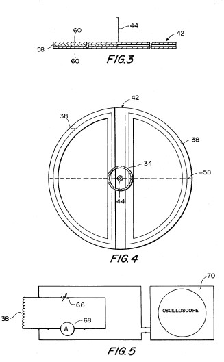
FIG. 4 is a plan view taken along line 4--4 of FIG. 2 illustrating the relationship of the sensing coils and superconductive blocking element; and
FIG. 5 illustrates an oscilloscope circuit used to measure the electrical power produced by the apparatus.
Referring to FIG. 1, the present invention is embodied as a superconductive electrical generator unit, generally 20, adapted to be immersed in a low temperature vessel, e.g., a Dewar tank 22, to maintain the generator unit at temperatures near absolute zero (0.degree. K.). Generator unit 20 includes a circular plate or cover 24 provided with a plurality of support rods 26 extending downwardly from the circular plate. Preferably, a set of three (3) equidistantly spaced support rods 26 is provided adjacent to the periphery of plate 24. Each support rod includes a threaded portion 28 at its lower end for receiving a pair of nuts 30 (FIG. 2). A platform 32, consisting of a circular base, is secured to support rod 26 by nuts 30. In the preferred embodiment, the base is provided with spaced holes (not shown) to reduce its mass. Circular plate 24 supports a rigid tube 34 located at the center of the plate and extending axially downward.
In the apparatus of the present invention, a permanent magnet is provided for generating a magnetic field. Referring to FIGS. 1 and 2, generator unit 20 includes a permanent magnet 36 mounted on platform 32 beneath the lower end of tube 34. The magnet preferably consists of a solid cylindrical piece of permanently magnetized material. Alternatively a magnet assembly consisting of a plurality of smaller permanent magnets is arranged in a circular configuration on platform 32. The purpose of the permanent magnet is to establish a stationary, uniform magnetic field for the generator.
In accordance with the present invention, the apparatus is provided with sensing means responsive to the magnetic field established by the permanent magnet for producing electrical energy in response to changes in the magnetic field. Preferably, the sensing means comprises one or more coils located within the magnetic field established by the permanent magnet. Referring to FIG. 1, a pair of coils 38 is mounted at the lower end of tube 34, e.g., by conventional bonding technique or other adhesive. Each coil consists of a plurality of turns of insulated wire and includes a set of leads 40 for electrical connection to an output circuit. The coils are arranged in a side-by-side configuration to respond to different portions of the magnetic flux from permanent magnet 36.
Further, in accordance with the invention, blocking means is interposed between the permanent magnet and the sensing means for periodically interrupting the magnetic field from the permanent magnet. Preferably, a magnetic field control device mounted for movement between the permanent magnet and sensing coil includes an element of diamagnetic material for shielding the sensing coil from the magnetic field upon interposition of the element between the magnet and the coil. In the preferred embodiment, the magnetic field control device comprises a rotatable blocking element of soft superconductive material rendered impermeable to the magnetic field at temperatures near absolute zero and adapted to alternately block and pass the magnetic field from the permanent magnet upon rotation of the blocking element to produce electrical energy in the coil.
Referring to FIGS. 1 and 2, a disc, generally 42, is rotatably mounted between permanent magnet 36 and sensing coils 38. The disc is attached at the lower end of a shaft 44 rotatably mounted within tube 34 by a plurality of sleeve bearings 45 provided at spaced locations in the tube. A magnetic control element 46, e.g., a piece of magnetized material such as alnico 8, is mounted on tube 34 to permit the demagnetizing effects of temperature and other conditions to be determined. The upper end of shaft 44 is connected through a coupling 47 to a motor 48 mounted on a circular platform 50 supported by a plurality of rods 52 extending upward from circular plate 24. Each rod 52 is provided with a threaded portion 54 at its upper end for receiving a pair of nuts 56 which are employed to clamp platform 50 to the rods.
Since tube 34 and shaft 44 provide a heat conductive path from the interior to the exterior of the low temperature vessel, it is contemplated that these components can be constructed to minimize the amount of heat transfer from the vessel. For example, the tube and shaft can be constructed of insulating material, e.g., a rigid plastic such as teflon, to minimize heat conduction. Further, it is contemplated that alternative pressure or magnetic coupling arrangements, which do not require mechanical connection between the motor and the disc, can be provided to eliminate the requirement of a continuous shaft extending from the interior to the exterior of the vessel.
Referring to FIGS. 3 and 4, the magnetic field control device consists of a thin, semi-circular element 58 of niobium placed between a pair of circular elements 60 of magnetically inert material. Alternatively, other soft superconductive material, e.g., mercury, lead, aluminum, vanadium, lanthanum, or technetium may be used in place of niobium, if desired. In addition, it is possible to employ hard superconductive materials with an appropriate adjustment in the magnetic field strength. Niobium element 58 and magnetically permeable elements 60 are held together by any suitable arrangement, e.g., bonding or adhesive tape. The resulting disc comprises a semi-circular portion of soft superconductive material (niobium) rendered impermeable to the magnetic flux at temperatures near absolute zero and a semi-circular portion of magnetically inert material. Disc 42 is located in a position relative to permanent magnet 36 to place superconductive element 58 at a magnetic field strength slightly below its critical field.
Alternatively, it is contemplated that mechanisms other than a superconductive blocking element can be used to provide a suitable magnetic field blocking device. For example, in the field of plasma physics, it is recognized that ionized gases known as plasmas exhibit the property of diamagnetism. Such materials, if confined in a suitable container, would be appropriate, in place of the soft superconductive material of the preferred embodiment, to provide a unit in which the magnetic field applied to the sensing coils is periodically interrupted. Of course, such a modified device would not require the low temperature medium of the preferred embodiment.
As shown in FIG. 2, a voltage supply circuit including a variable power supply 62 for converting conventional AC voltage to DC voltage provides a suitable DC voltage input for operating motor 48. A common current wattmeter 64 is connected across the AC input lines to the variable power supply to indicate the power consumption of the motor.
The circuit of FIG. 5 is used to determine the output power produced by the generator. This circuit includes a variable resistor 66 and an ammeter 68 which can be connected in series across either coil 38 of the generator. The resistance serves as a load and the ammeter measures the load current. In addition, an oscilloscope 70 is connected across the coil to measure the output voltage. The product of the load current and output voltage equals the output power.
In the operation of the apparatus, generator unit 20 is inserted into Dewar tank 22 with circular plate 24 resting on the upper edge of the tank. Liquid helium is applied to the interior of the tank up to the dashed line shown in FIG. 2 to cool the niobium element to a temperature near absolute zero. The position of disc 42 is set relative to magnet 36 by adjustment of platform 50 on rods 52 to locate niobium element 58 slightly above the position at which the flux density of the magnetic field renders the niobium element a normal conductor. At temperatures near absolute zero, niobium exhibits diamagnetism and the Meissner effect. Thus, when interposed between magnet 36 and either of the coils, niobium element 58 blocks the magnetic flux from the magnet to the coil.
When motor 48 is energized to rotate disc 42, niobium element 58 operates to alternately block and pass the magnetic flux from magnet 36 to coils 38. When niobium element 58 is located entirely below either coil, the coil is completely shielded from the magnetic flux. At the same time, the other coil is completely exposed to the magnetic flux. At all other times, each coil is partially shielded and partially exposed to the magnetic flux.
As a result of rotation of disc 42 and niobium element 58, each coil 38 is subjected to a continuously changing magnetic field. A voltage is induced in each coil which is proportional to the rate of change of the magnetic flux through the coil. When the coil is connected to an output circuit, such as the circuit of FIG. 5, the output power produced by the generator can be determined by measuring its output voltage and load current.
Example
In a specific example of a generator unit constructed according to the principles of the present invention, circular plate or cover 24 is made of aluminum six and three-quarter inches (63/4") in diameter and one inch (1") in thickness. It serves as a cover for Dewar tank 22 which has an inner diameter of five and three-quarter inches (53/4"). Support rods 26 comprise hollow stainless steel tubes with a wall thickness of 0.03 inch and an outer diameter of one-half inch (1/2"). Platform 32 is made of steel one-eight inch (1/8") in thickness and is provided with spaced holes (not shown) approximately one-half inch (1/2") in diameter to reduce its mass.
Tube 34 is made of stainless steel with an outer diameter of one and one-half inches (11/2") and an inner diameter of 1.435 inches. Magnet 36 comprises a substantially circular assembly of bar magnets of alnico 8 material. The magnet has a maximum field strength of approximately 4800 gauss.
Each coil 38 consists of AWG #18 wire and includes approximately one hundred (100) turns. Each coil is substantially semi-circular in configuration with a radius of 2.25 inches, a height of 0.7 inch, and a depth of 0.2 inch.
Shaft 44 is made of stainless steel one-eighth inch (1/8") in diameter. Disc 42 attached to the lower end of shaft 44 includes semi-circular element 58 of niobium, approximately 0.001 inch in thickness and 99.84% pure, and two (2) circular elements 60 composed of cardboard. The disc is approximately four and one-half inches (41/2") in diameter.
In a representative operation, the position of disc 42 was set by adjustment of the level of platform 50 to place the disc slightly above the flux density (approximately 2000 gauss) at which niobium element 58 behaves as a normal conductor. The disc was rotated at one thousand (1000) revolutions per minute and readings on each coil 38 were taken. The value of resistance 66 (FIG. 5) was varied. The wattage consumed by motor 48 was roughly 7 watt plus or minus 2.5 watts. The wattage output measured by the circuit of FIG. 5 was approximately 11.4 watts maximum. The V.sub.RMS of each coil was 1.14 volts plus or minus 0.5 volts. V.sub.MAX was 1.612 volts and I.sub.RMS was about 10 amps. Wattmeter readings were divided by the product of the oscilloscope and ammeter readings to determine the power factor which was very close to unity.
The generator unit of the present invention provides a highly efficient device for producing electrical energy from a magnetic field. It produces an enhanced electrical output in comparison with the input energy required to drive the unit. It is anticipated that a portion of the enhanced electrical output can be used for operation of the cooling apparatus to provide liquid helium and another portion of the electrical output can be used to provide input energy to drive the motor of the generator unit.
The invention in its broader aspects is not limited to the specific details shown and described, and modifications may be made in the details of the generator unit without departing from the principles of the present invention.
US4237391
Apparatus for producing electrical
energy
Abstract -- An electrical generator comprises a stationary permanent magnet for establishing a magnetic field, one or more sensing coils responsive to the magnetic field, and a diamagnetic blocking element movable between the magnet and the sensing coils for periodically interrupting the magnetic field to produce electrical energy in the coils. A preferred embodiment includes a pair of semi-circular coils arranged side-by-side in the magnetic field and a rotatable blocking disc interposed between the magnet and the coils. The disc includes a semi-circular portion of superconductive material rendered impermeable to the magnetic field at temeperatures near absolute zero and a semi-circular portion of magnetically inert material to alternately block and pass the magnetic field to the coils upon rotation of the disc.
USP App 20090082208
SUPERCONDUCTING GENERATOR
Abstract -- A generator that comprises at least one ferromagnetic core including a gap, a magnet capable of producing a normal magnetic field within said gap and at least one coil positioned within the normal magnetic field on the core. At least one diamagnet that is positioned to pass through said gap on said core, wherein the diamagnet momentarily blocks the normal magnetic field causing a voltage to be induced within said coil.
BACKGROUND OF THE INVENTION
[0001] The invention relates to generators.
BRIEF SUMMARY OF THE INVENTION
[0002] A first embodiment of the invention is a generator comprising at least one ferromagnetic core including a gap; a magnet positioned on said at least one ferromagnetic core producing a normal magnetic field within said gap; at least one coil positioned within the normal magnetic field on said at least one ferromagnetic core; at least one diamagnet rotatably positioned to pass through said gap on said at least one ferromagnetic core, wherein rotation of said at least one diamagnet that momentarily blocks the normal magnetic field causing a voltage to be produced withing said at least one coil.
[0003] A second embodiment of the invention is a superconducting generator comprising: at least one rotatable ferromagnetic core including a gap; a magnet positioned on said at least one ferromagnetic core producing a normal magnetic field; a coil positioned within the field on said at least one ferromagnetic core; and at least one fixed superconducting diamagnet positioned to pass through said gap on said at least one ferromagnetic core when said core is rotated.
[0004] A third embodiment of the invention is a superconducting generator comprising: a plurality of ferromagnetic cores arranged in a circle, wherein each core includes a gap; a magnet positioned on each of said plurality of ferromagnetic cores producing a normal magnetic field within each said core and said gap; at least one coil positioned within the normal magnetic field on each said plurality of ferromagnetic cores; a plurality of superconducting diamagnet positioned and configured to pass through each said gap on said plurality of ferromagnetic cores, wherein rotation of either said plurality of superconducting diamagnets or plurality of ferromagnetic cores with respect to each other momentarily blocks the normal magnetic field causing a voltage to be produced withing said at least one coil.
BRIEF DESCRIPTION OF THE DRAWINGS
[0005] Some of the embodiments of this invention will be described in detail, with reference to the following figures, wherein like designations denote like members, wherein:
[0006] FIG. 1 depicts a side view of the core;

[0007] FIG. 2 depicts a side view of a second embodiment of the core;

[0008] FIG. 3 depicts a diamagnetic superconductor that is optionally encased with a dewar;

[0009] FIG. 4 depicts a plurality of cores with a centrally facing gap and a plurality rotated superconductor;

[0010] FIG. 5 depicts a plurality of rotating cores with an externally facing gap and a plurality of externally mounted fixed diamagnets;

[0011] FIG. 6 depicts a top view of a plurality of cores arranged in a circular pattern that are rotated to move fixed diamagnets within that gap;

[0012] FIG. 7 depicts a top view of a plurality of diamagnets rotated within a circular formation of inwardly facing cores; and

[0013] FIG. 8 depicts a side view of a stacked circular arrangement of cores and diamagnets.

DETAILED DESCRIPTION OF THE INVENTION
[0014] Although certain preferred embodiments of the present invention will be shown and described in detail, it should be understood that various changes and modifications may be made without departing from the scope of the appended claims. The scope of the present invention will in no way be limited to the number of constituting components, the materials thereof, the shapes thereof, the relative arrangement thereof, etc., and are disclosed simply as an example of an embodiment. The features and advantages of the present invention are illustrated in detail in the accompanying drawings, wherein like reference numerals refer to like elements throughout the drawings.
[0015] As a preface to the detailed description, it should be noted that, as used in this specification and the appended claims, the singular forms "a", "an" and "the" include plural referents, unless the context clearly dictates otherwise. In the invention a diamagnet 200, which may be from a superconducting material, acts as a blocking device that moves with respect to a gap 115 in a core 110 having a magnetic field 130 that includes a coil 140, wherein the diamagnet 200 periodically shields and unshields the magnetic field 130 inducing an EMF (Electro Motive Force) generating a voltage or current 195 from the coil 140. The invention provides for the efficient transformation of the energy of the magnetic field 130 into electrical energy from movement of the diamagnet 200 with respect to the gap 115 in the core 110.
[0016] Faraday's Law states that the induced emf around a closed mathematical path in a magnetic field is equal to the rate of change of magnetic flux intercepted by the area within the path. Inefficient systems can use large amounts of energy to change the magnetic flux and produce the electromotive force while more efficient methods for changing the flux may be used to produce the same electromotive force for far less energy. Thus, the efficiency in the production of the emf is a product of the efficiency in changing the magnetic flux which passes through the closed circuit.
[0017] The blocking of the magnetic field 130 in the core 110 occurs when a diamagnetic object passes through the gap 115, where the diamagnetism is caused by the Meissner effect of superconductive materials (i.e., the diamagnetic properties of a superconductive material 200 may occur in specific materials when operating at a temperature below its transition temperature) that are exploited to provide a device 100 for producing electrical energy from a magnetic field 130. A superconductive element 200, either a high temperature or low temperature type, is maintained at a temperature immediately below its transition temperature or colder and periodically it acts to shield a coil 140 from a magnetic field established by a permanent or electromagnet 120 causing a changing flux within the coil 140 to induce and EMF.
[0018] A ferromagnetic core 110 is used that has suitable properties to establish a magnetic field 130 within its body with a magnet 20. The core 110 may be a circular or closed geometric shape, such as a square to allow a continuous magnetic field to be guided. The core 110 can also be made of electrical steel, also called lamination steel, silicon electrical steel, silicon steel or transformer steel, all of which are specialty steels tailored to produce certain magnetic properties, such as a small hysteresis area (small energy dissipation per cycle, or low core loss) and high permeability. The core material 110 may be manufactured in the form of cold-rolled strips less than 2 nm thick called laminations that may form a core 110 when stacked together. Laminations may be cut to their finished shape by a punch and die, or in smaller quantities may be cut by a laser. The core 110 of the instant invention may be shaped in any manner that allows a magnetic loop 130 to be formed within and across the gap 115.
[0019] A coil 140 induces an EMF in response to the magnetic field 130 that passes through a gap 115 within the core 110 that is temporarily blocked or disrupted when a diamagnet 200 is interposed between the field of the magnet 120 and the coil 140 by passing within the gap 115 of the core 110. The magnetic field 130 within the core 110 can be from either a permanent or electromagnet 120. The diamagnet 200 is a magnetic flux shielding device that moves with respect to the gap 115 in the core 110 to alternately shield and unshield the magnetic flux from the coil 140. The core 110 as discussed above may be made of a ferro-magnetic material such as transformer steel or the like which would enclose and confine the field of the magnet dipole 120 to ensure that it passes through the gap 115. The invention is not effected by the position of the coil 140 and magnet 120, which may be placed anywhere upon the core 110.
[0020] A superconducting generator 100 of the invention comprises at least one ferromagnetic core 110 including a gap 115 having a magnet 120 positioned on the ferromagnetic core 110 producing a normal magnetic field 130 within said gap 115 and at least one coil 140 positioned within the normal magnetic field 130 on said at least one ferromagnetic core 110 as shown in FIGS. 1 and 2. The superconductor generator 100 includes at least one superconducting diamagnet 200 that is rotatably positioned adjacent to said core 110 to allow the diamagnet 200 to pass through said gap 115 as shown in FIG. 4. An EMF is induced in the coil 140 on the ferromagnetic core 110 when rotation of said at least one superconducting diamagnet 200 momentarily blocks the normal magnetic field 130 causing a changing magnetic flux within at least one coil 140.
[0021] The blocking device 200 must be kept below the transition temperature of the specific superconducting material used, either type I or type II or the Meisner effect is temporarily destroyed removing the properties of diamagnetism and therefore preventing blocking of the magnetic field 130 passing through the gap 115. One solution to maintain diamagnetism properties of the superconductor is to cool the whole superconducting apparatus 100 including the core 110, magnet 120 and coil 140 along with the diamagnet 200 and all attached assemblies below the superconducting material's critical temperature used in the application. Another option is by having the superconducting generator 100 further comprise, as shown in FIG. 3, a dewar 225 surrounding said superconducting diamagnet 200, said dewar 225 is dimensioned to pass through the gap 115 on the core 110. The use of a dewar 225 dimensioned to pass within the gap 115 of the core 110 allows for cooling only of the diamagnetic material 200 and the remaining constituents of the generator 100 remain at a more economically desirable temperature above the critical temperature of the superconductor 200 that is desirable from the standpoint of cooling costs and storage requirements.
[0022] A superconductor placed in a weak external magnetic field H 130 permits the field 130 to penetrate the superconductor a short distance called the London penetration depth before it decays rapidly to zero (blocked), which is called the Meissner effect, and is a defining characteristic of superconductivity. The Meissner effect is different than the diamagnetism in a perfect electrical conductor that according to Lenz's law, when a changing magnetic field is applied to a conductor, it will induce an electrical current in the conductor that creates an opposing magnetic field. In a perfect conductor, an arbitrarily large current can be induced, and the resulting magnetic field exactly cancels the applied field.
[0023] The Meissner effect is distinct from this because a superconductor expels all magnetic fields, not just those that are changing. Suppose we have a material in its normal state, containing a constant internal magnetic field that when the material is cooled below the critical temperature (Tc), we would observe the abrupt expulsion of the internal magnetic field, which we would not expect based on Lenz's law.
[0024] The Meissner effect breaks down when the applied magnetic field 130 is too large and thus ceases to be able to function as a diamagnet. Type I superconductors may be abruptly destroyed (superconductivity) when the strength of the applied field rises above a critical value Hc. Depending on the defects and flux pinning of the sample, one may obtain an intermediate state consisting of regions of normal material carrying a magnetic field mixed with regions of superconducting material containing no field. In Type II superconductors, raising the applied field past a critical value H.sub.c1 leads to a mixed state in which an increasing amount of magnetic flux penetrates the material, but there remains no resistance to the flow of electrical current as long as the current is not too large. At a second critical field strength Hc2, superconductivity is destroyed because the mixed state is actually caused by vortices in the electronic superfluid, sometimes called fluxons because the flux carried by these vortices is quantized. Therefore, the magnetic field 130 in the core 110 of the generator 100 must use a magnetic source 120 weaker than Hc with Type 1 superconductors and weaker than H.sub.c1 for Type 2 superconductors.
[0025] The diamagnet of the invention may be a type 1 superconductors that may require the coldest temperatures to become superconductive and are elemental and very pure in nature. The type 1 superconductors listed below exhibit a very sharp transition to a superconducting state and a "perfect" diamagnetism the ability to repel a magnetic field completely. The instant invention may use the Type 1 superconductor Niobium (Nb) that below a temperature of 8K has an Hc of about 2,000 gauss, which has the highest Hc of the currently known type 1 and type 2 superconductors.
[0026] Below is a list of other known Type 1 superconductors along with their critical transition temperature (known as Tc) below which each superconducts. Lead (Pb) 7.196 K; Lanthanum (La) 4.88 K; Tantalum (Ta) 4.47 K; Mercury (Hg) 4.15 K; Tin (Sn) 3.72 K; Indium (In) 3.41 K; Palladium (Pd)* 3.3 K; Chromium (Cr)* 3 K; Thallium (Tl) 2.38 K; Rhenium (Re) 1.697 K; Protactinium (Pa) 1.40 K; Thorium (Th) 1.38 K; Aluminum (Al) 1.175 K; Gallium (Ga)1.083 K; Molybdenum (Mo) 0.915 K; Zinc (Zn) 0.85 K; Osmium (Os)0.66 K; Zirconium (Zr)0.61 K; Americium (Am) 0.60 K; Cadmium (Cd) 0.517 K; Ruthenium (Ru) 0.49 K; Titanium (Ti) 0.40 K; Uranium (U)0.20 K; Hafnium (Hf)0.128 K; Iridium (Ir) 0.1125 K; Beryllium (Be)0.023 K (SRM 768); Tungsten (W)0.0154 K; Platinum (Pt)* 0.0019 K; Lithium (Li)0.0004 K; Rhodium (Rh) 0.000325K
[0027] The next superconducter possible to use is a Type 2 category of superconductors that includes metallic compounds and alloys. The highest Tc attained at ambient pressure for a material that will form stoichiometrically (by formula) has been 138 K and a patent has been applied for a 150K material which does not form stoichiometrically (see below list). Type 2 superconductors differ from Type 1 in that their transition from a normal to a superconducting state is gradual across a region of "mixed state" behavior. A Type 2 will allow some penetration by an external magnetic field into its surface. While there are far too many known to one skilled in the art to list in totality, some of the more interesting Type 2 superconductors are listed below by similarity and with descending Tc's
[0028] One skilled in the art would naturally substitute a later discovered type 2 superconductor having superior properties and higher Tc and should be considered as an equivalent. While type 2 superconductors known currently have a much higher Tc than type 1 superconductors the critical magnetic field is an order of magnitude smaller at about 200 gauss than Niobium (Nb) having 2,000 gauss, which directly impacts the amount of current generated by each coil 140 on each core 110.
[0029] A partial list of suitable type 2 superconductors than may be used is as follows: InSnBa.sub.4Tm.sub.4Cu.sub.6O.sub.18+.about.150 K; (Hg.sub.0.8Tl.sub.0.2)Ba.sub.2Ca.sub.2Cu.sub.38.33138K; HgBa.sub.2Ca.sub.2Cu.sub.3O.sub.8 133-135K; HgBa.sub.2Ca.sub.3Cu.sub.4O.sub.10+ 125-126K; HgBa.sub.2(Ca.sub.1-xSr.sub.x)Cu.sub.2O.sub.6+ 123-125K; HgBa.sub.2CuO.sub.4+ 94-98K; Tl.sub.2Ba.sub.2Ca.sub.2Cu.sub.3O.sub.10 127-128K; (Tl.sub.1.6Hg.sub.0.4)Ba.sub.2Ca.sub.2Cu.sub.3O.sub.10+123K; TlBa.sub.2Ca.sub.2Cu.sub.3O.sub.9+ 118-120K; (Tl.sub.0.5Pb.sub.0.5)Sr.sub.2Ca.sub.2Cu.sub.3O.sub.9 118K; Tl.sub.2Ba.sub.2CaCu.sub.2O.sub.6 115K; (Tl.sub.0.5Sn.sub.0.5)Ba.sub.2(Ca.sub.0.5Tm.sub.0.5)Cu.sub.2O.sub.x 112K; TlBa.sub.2Ca.sub.3Cu.sub.4O.sub.11 103K; TlBa.sub.2CaCu.sub.2O.sub.7+ 95K; Sn.sub.2Ba.sub.2(Ca.sub.0.5Tm.sub.0.5)Cu.sub.3O.sub.8+ 115K; SnInBa.sub.4Tm.sub.3Cu.sub.5O.sub.x 113K; Sn.sub.3Ba.sub.4Tm.sub.3Cu.sub.6O.sub.x 109K; Sn.sub.3Ba.sub.8Ca.sub.4Cu.sub.11O.sub.x 109K; SnBa.sub.4Y.sub.2Cu.sub.5O.sub.x 105K; Sn.sub.4Ba.sub.4Tm.sub.2YCu.sub.7O.sub.x 104K; Sn.sub.4Ba.sub.4CaTmCu.sub.4O.sub.x 100K; Sn.sub.4Ba.sub.4Tm.sub.3Cu.sub.7O.sub.x 98K; Sn.sub.2Ba.sub.2(Y.sub.0.5Tm.sub.0.5)Cu.sub.3O.sub.8+ 96K; Sn.sub.3Ba.sub.4Y.sub.2Cu.sub.5O.sub.x 91K; SnInBa.sub.4Tm.sub.4Cu.sub.6O.sub.x 87K; Sn.sub.2Ba.sub.2(Sr.sub.0.5Y.sub.0.5)Cu.sub.3O.sub.8 80K; Sn.sub.4Ba.sub.4Y.sub.3Cu.sub.7O.sub.x 80K; Bi.sub.1.6Pb.sub.0.6Sr.sub.2Ca.sub.2Sb.sub.0.1Cu.sub.3O.sub.y 115K; Bi.sub.2Sr.sub.2Ca.sub.2Cu.sub.3O.sub.10 110K; Bi.sub.2Sr.sub.2CaCu.sub.2O.sub.9 110K; Bi.sub.2Sr.sub.2(Ca.sub.0.8Y.sub.0.2)Cu.sub.2O.sub.8 95-96K; Bi.sub.2Sr.sub.2CaCu.sub.2O.sub.8 91-92K; (Ca.sub.1-xSr.sub.x)CuO.sub.2 110K; YSrCa.sub.2Cu.sub.4O.sub.8+ 101K; (Ba,Sr)CuO.sub.2 90K; BaSr.sub.2CaCu.sub.4O.sub.8+ 90K; (La,Sr)CuO.sub.2 42K; Pb.sub.3Sr.sub.4Ca.sub.3Cu.sub.6O.sub.x 106K; Pb.sub.3Sr.sub.4Ca.sub.2Cu.sub.5O.sub.15+ 101K; (Pb.sub.1.5Sn.sub.1.5)Sr.sub.4Ca.sub.2Cu.sub.5O.sub.15+ 95K; Pb.sub.2Sr.sub.2(Ca, Y)Cu.sub.3O.sub.8 70K; AuBa.sub.2Ca.sub.3Cu.sub.4O.sub.11 99K; AuBa.sub.2(Y, Ca)Cu.sub.2O.sub.7 82K; AuBa.sub.2Ca.sub.2Cu.sub.3O.sub.9 30K; (Y.sub.0.5Lu.sub.0.5)Ba.sub.2Cu.sub.3O.sub.7 107K; (Y.sub.0.5Tm.sub.0.5)Ba.sub.2Cu.sub.3O.sub.7 105K; (Y.sub.0.5Gd.sub.0.5)Ba.sub.2Cu.sub.3O.sub.7 97K; Y.sub.2CaBa.sub.4Cu.sub.7O.sub.16 97K; Y.sub.3Ba.sub.4Cu.sub.7O.sub.16 96K; NdBa.sub.2Cu.sub.3O.sub.7 96K; Y.sub.2Ba4Cu.sub.7O.sub.15 95K; GdBa.sub.2Cu.sub.3O.sub.7 94K; YBa.sub.2Cu.sub.3O.sub.7 92K; TmBa.sub.2Cu.sub.307 90K; YbBa.sub.2Cu.sub.307 89K; YSr.sub.2Cu.sub.307 62K; GaSr.sub.2(Ca.sub.0.5Tm.sub.0.5)Cu.sub.2O.sub.7 99K; Ga.sub.2Sr.sub.4Y.sub.2CaCusO, 85K; Ga.sub.2Sr.sub.4.TM..sub.2CaCusO5 81K; La.sub.2Ba.sub.2CaCu.sub.5O.sub.9+79K; (Sr,Ca).sub.5Cu.sub.4Oi.sub.0 70K; GaSr.sub.2(Ca, Y)Cu.sub.2O.sub.7 70K; (In.sub.0.3Pb.sub.0.7)Sr.sub.2(Ca.sub.0.8Yo..sub.2)Cu.sub.2Ox 60K; (La,Sr,Ca).sub.3Cu.sub.2O.sub.6 58K; La.sub.2CaCu.sub.2O.sub.6+45K; (Eu,Ce).sub.2(Ba,Eu).sub.2Cu.sub.3O.sub.10+43K; (Lal 0.85Sro. .sub.5)CuO.sub.4 40K; SrNdCuO 40K; (La,Ba).sub.2CuO.sub.4 35-38K; (Nd,Sr,Ce).sub.2CuO.sub.4 35K; Pb.sub.2(Sr,La).sub.2Cu.sub.206 32K; (Lal..sub.85Ba..sub.15)CuO.sub.4 30K; MgB.sub.2 39K; Ba.sub.0.6K.sub.04BiO.sub.3 30K; Nb.sub.3Ge 23.2K; Nb.sub.3Si 19K; Nb.sub.3Sn 18.1K; Nb.sub.3Al 18K; V.sub.3Si17.1K; Ta.sub.3Pb 17K; V.sub.3Ga 16.8K; Nb.sub.3Ga 14.5K; V.sub.3In 13.9K; PuCoGa.sub.5 18.5K; NbN 16.1K; and many others.
[0030] The superconducting generator 100 of FIG. 7 may further comprise a rotatable carrier 300, wherein said at least one superconducting diamagnet 200 is mounted thereupon. A coolant 325 may be provided to the superconducting diamagnets 200 to prevent transition to the normal state through supports including circulating conduits 330. The superconducting generator 100 further comprises a rotatable shaft 310 connected to said rotatable carrier 300, wherein said rotatable shaft contains ducts 320 to circulate said coolant 325. In addition to the coolant circulation 325 an insulating member 225 may surround said at least one superconducting diamagnet 200 to maintain a temperature sufficient to maintain superconductivity through proving insulation.
[0031] The superconducting generator 100 includes a magnet 120 on each core 110 that may either be a permanent magnet or an electromagnet. The magnet 120 is selected to produce a field strength below the critical field strength (saturation point) of the selected superconductor, which is about 200 gauss for a Type 2 superconductor. The superconducting generator 400 of FIG. 7 shows an embodiment of a device 400 with an arrangement of a plurality of cores 111 that allows increased electrical higher output while using a higher temperature Type 2 superconductor 200 having an Hc of 200 gauss or less wherein a plurality of ferromagnetic cores 111 are arranged in a circle, wherein said gap 115 faces inwards. A plurality of rotatable carriers 330 each having at least one superconducting diamagnet 200 is mounted thereupon in a circularly spaced fashion to allow rotation. The amount of diamagnets 200 and cores 111 present are determined by the rotational force (torque) provided to a rotatable shaft 310 connected to said plurality of rotatable carriers 330. The plurality of ferromagnetic cores 111 are arranged in a circle forming a ring of magnetic fields 131, wherein each of said plurality of rotatable carriers 200 rotates within said ring of magnetic fields 131 by passing through the gap 115. The number of cores, and diamagnets are determined by the torque input, desired output, the strength of the diamagnet that determine individual field strength that directly correlates to individual coil outputs and required operating temperature.
[0032] Another embodiment of the superconducting generator 500 as shown in FIG. 6 comprises at least one rotatable ferromagnetic core 110, 710 including a gap 115 having a magnet 120 positioned on said ferromagnetic core 110 producing a normal magnetic field 130. A coil 140 is positioned within the field 130 on each ferromagnetic core 110, 710. The core 110 is rotated in relation to at least one fixed superconducting diamagnet 200 that is positioned to pass through said gap 115 on said at least one ferromagnetic core 110, 710 when said core 110 is rotated.
[0033] The superconducting generator 600 may further comprising a positioning member 410, wherein a plurality of superconducting diamagnets 420 are mounted thereupon in a circularly spaced fashion. A plurality of ferromagnetic cores 710 arranged in a circle forming a ring of parallel magnetic fields 720, wherein said ring of parallel magnetic fields 720 is rotated so that said plurality of superconducting diamagnets 420 on the positioning member blocks said ring of parallel magnetic fields 720 during rotation.
[0034] The superconducting generator 600 of FIG. 6 further comprises a vessel 520 having a wall 525 that may include insulation 528 and cryogen 530 therein circulating to cool the plurality of superconducting diamagnets 200 that are mounted to extend therefrom in a circularly spaced fashion on said wall 525 of said vessel 520. A rotatable shaft 550 is operably attached to a plurality of ferromagnetic cores 710 arranged in a circle. The plurality of cores 710 are not in physical or electrical contact so as to form a ring of parallel magnetic fields 730 that are mounted to said rotatable shaft 550. The plurality of ferromagnetic cores 710 have said gap 115 facing outwards and is positioned within said vessel 520 so that said diamagnets 200 on said vessel wall 525 momentarily blocks said fields 730 during rotation when passing within said gap 115. The superconducting generator 600 may include a cryogen or cryogenic refrigeration 530 within said vessel wall 525 to chill said attached, affixed or partially embedded superconducting diamagnets 200 to allow the plurality of ferromagnetic cores 710 to be maintained at a temperature above a critical superconducting temperature.
[0035] The dewar 225 as shown in FIG. 3 may be made of glass, stainless steel or any other material that does not have magnetic or electric properties at the low required temperatures below the Tc of the superconductor 200. The shape of the superconductor 200 within the dewar 225 can be modified to adjust the output waveform of the coil 140. The diamagnet shape 202 may be changed to a circular shape, square, rectangular, or rod like to create a square, triangular or sinusoidal wave pattern from said EMF output of said coil 140.
[0036] A superconducting generator 800 as shown in FIG. 8 comprises a plurality of ferromagnetic cores 810 arranged in a circle, wherein each core as shown in FIG. 1 includes a gap 115 and a magnet 120 that produces a normal magnetic field 130 within each core 110 and across the gap 115. There is at least one coil 140 positioned within the normal magnetic field 130 on each ferromagnetic core. The plurality of cores arranged in a circle 810 may be stacked upon each other and share a common rotation shaft 820 that can be configured to rotate either the plurality of cores arranged in a circle 810 or a plurality of superconducting diamagnets 220 positioned and configured to pass through each said gap 115 on said plurality of ferromagnetic cores 810. The rotation of the shaft 820 depending on the desired configuration allows movement of either said plurality of superconducting diamagnets 220 or plurality of ferromagnetic cores 810 with respect to each other to momentarily block the normal magnetic field 130 causing a voltage to be produced within said at least one coil 140.
[0037] Various modifications and variations of the described apparatus and methods of the invention will be apparent to those skilled in the art without departing from the scope and spirit of the invention. Although the invention has been described in connection with specific embodiments, outlined above, it should be understood that the invention should not be unduly limited to such specific embodiments. Various changes may be made without departing from the spirit and scope of the invention as defined in the following claims.
FR2422280
GENERATEUR ELECTRIQUE POUR
TRANSFORMER UN CHAMP MAGNETIQUE STATIONNAIRE EN ENERGIE
ELECTRIQUE UTILE
DE2813794
EINRICHTUNG ZUR ERZEUGUNG
VON ELEKTRISCHER ENERGIE
