USP #
5,782,225 -- Vaporization system
Caggiono,
Allen

Abstract
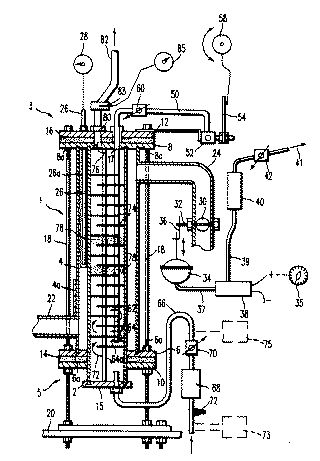
-- A fluid vaporization system comprises a first fluid
inlet for receiving a first fluid, a second fluid inlet for
receiving a second fluid, and a first discharge aperture for
discharging the first fluid and the second fluid. A first
connecting passage connects the first fluid inlet and the
second fluid inlet in fluid communication with the first
discharge aperture, mixes the first fluid and the second fluid
to define a fluid mixture, and delivers the fluid mixture to
the first discharge aperture. A third fluid inlet receives a
third fluid and a second discharge aperture discharges the
third fluid. A second connecting passage in heat transfer
relationship with the first connecting passage connects the
third fluid inlet in fluid communication with the second
discharge aperture and delivers the third fluid from the third
fluid inlet to the second discharge aperture to effect heat
transfer from the third fluid to the fluid mixture such that
the fluid mixture is discharged by the first discharge
aperture in a vaporized state.
USP # 5,606,956
-- Elongated fuel-air bypass for internal combustion engine
Wallace, William

Abstract
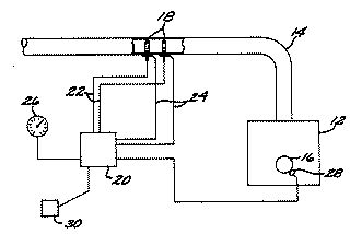
-- An elongated fuel-air bypass is connected between an
outlet port of a fuel-air mixing device and an inlet port of
an intake manifold of an internal combustion engine. The
elongated bypass apparatus includes an elongated bypass
conduit formed of a thermally conductive material and which
has sufficient length, exterior surface area and thermal
conductivity to enable it to cause liquid fuel introduced
through the fuel-air mixing device to change from a liquid
state to a gaseous state prior entry into the one or more
cylinders of the internal combustion engine. Turbulence
creating mechanisms, such as venturis or baffles, are provided
in the elongated bypass conduit for creating turbulence in the
fuel-air mixture flowing therethrough. An after-air supply
tube is provided to supply after-air near an upstream end of
the fuel-air bypass conduit, and is controlled by an after-air
valve to provide for a lean fuel-air mixture. Also provided is
a liquid additive system for supplying water and/or alcohol
into the fuel-air bypass conduit. A start-up fuel injection
system is provided to inject a burst of fuel into the fuel-air
bypass conduit at initial start-up of the internal combustion
engine. At least one reparticulation reservoir is provided in
the bottom of a portion of the fuel-air bypass conduit in
order to enable quick start-up of the engine after flooding.
USP # 5,598,826
-- Cold start fuel control system for an internal combustion
engine
Hunt, Frank &
Nogi, Toshiharu

Abstract
-- A cold start fuel control system provided for use
with an internal combustion engine of the type having at least
one combustion chamber, an air/fuel passageway fluidly
connected with the combustion chamber and the source of fuel.
The fuel control system includes an annular heater having an
interior annular wall disposed within the passageway. A cold
start fuel injector has its inlet fluidly connected to the
fuel source and an outlet open to the passageway such that
fuel from the outlet flows into the interior of the heater.
Whenever the operating temperature of the engine is below a
predetermined level, fuel is selectively provided to the cold
start fuel injector which injects fuel into the passageway.
The fuel discharge from the cold start fuel injector is
swirled so that at least a portion of the fuel from the cold
start fuel injector impinges upon the annular heater and is
thus vaporized.
USP # 5,555,855
-- Water circulation system for marine engine
Takahashi,
Masanori

Abstract
-- A water circulation system of a marine engine
improves the consistency of engine combustion by stabilizing
the temperature of water flowing through the engine water
jacket and by heating the intake manifold to a temperature
within a desired temperature range. The desired temperature
range is defined so as to optimize fuel vaporization without
significantly affecting the volumetric efficiency of the
engine. The water circulation system includes a control valve
which directs water flow through the circulation system
according to the water temperature exiting the engine water
jacket. The valve recirculates water between the engine water
jacket and a recirculation path until the water temperature
reaches a predetermined lower temperature limit. The control
valve then allows a portion of the water to flow through a
heating jacket around the intake manifold to heat the intake
manifold. If the temperature of the recirculating water
reaches a predetermined upper temperature limit, the control
valve directs all of the water through the heating jacket
until the temperature of the water exiting the engine water
jacket falls below the upper temperature limit. In this
manner, the water circulation system generally stabilizes the
water temperature in the engine water jacket and heats the
intake manifold to a temperature generally within the upper
and lower temperature limits.
USP # 5,396,866
-- Ram tube
Kuntz, Dennis

Abstract
-- The ram tube of this invention basically consists of
an intake bracket, inner tube, output bracket, outer tube,
input port and output port. The intake and output brackets are
attached to the ends of the inner tube for attaching the ram
tube to the base of a carburetor and the intake to an intake
manifold of an internal combustion engine. The outer tube is
installed over and surrounds the inner tube to create a
passage between the inner and outer tubes. Exhaust is directed
from the exhaust manifold of the engine to an input port on
the outer tube. The exhaust passes through the passage and
exits through the output port. The exhaust heats the inner
tube to in turn heat the air/fuel mixture passing through the
inner tube. The fuel is completely vaporized and placed in a
dry vapor condition as it passes through the heated inner
tube. The fuel entering the combustion chamber in a dry vapor
condition burns more completely, at a higher temperature and
at a faster rate to provide a higher efficiency engine. Due to
the high temperature achieved using the ram tube, water can be
injected into the ram tube or air stream for use as a fuel
supplement. The ram tube of this invention can also be used in
conjunction with a heat exchanger for initial vaporization of
fuel in cooler weather and/or a turbo charger, or other type
of device which increases volume efficiency, for pressurizing
the air/fuel mixture for additional engine performance.
USP # 5,353,772
-- Carburetor fuel charge heating apparatus
Wallace, W.

Abstract
-- An apparatus including a first chamber in operative
communication with a carburetor to receive carburetor fluid
flow therefrom, directing such fluid flow through a central
conduit into a second chamber in operative fluid communication
with an intake manifold of an associated internal combustion
engine, such that the central conduit is arranged for the
heating and associated gaseous flow from the carburetor to the
intake manifold.
USP # 5,335,639
-- Heat exchanger having close packed spheres
Siefkes; Donald

Abstract
-- An apparatus (16) for preheating combustion fluids
such as air, fuel or fuel-air mixtures upstream of the
combustion chamber in an internal combustion engine (10). The
apparatus (16) generally includes a heat exchanger (18) and an
assembly (46) for heating the heat exchanger. The improvement
involves constructing the heat exchanger (18) from a plurality
of closely-packed beads (20) each having a spherical shape and
each comprised of homogeneous aluminum filling the entire
space within the outer spherical shape to provide a high
surface area heat exchanger for heating the combustion fluid
as the fluid passes around the beads.
USP # 5,327,875
-- Vapor enhanced carburetion system
Hall; S. Franklin

Abstract
-- A carburetion system for an internal combustion
engine includes fuel vaporizing gun which operates as a heat
exchanger with heat from the engine exhaust manifold. The
system may be manually or automatically operative when hot
exhaust gases from the engine heat the gun to sufficient
temperatures for vaporizing the fuel. A vapor fuel shut-off
valve positioned on the vapor line to the engine intake ports
regulates the air to gas mixture to a ratio of between 15 and
16 to 1, for maximum combustion, increased fuel mileage and
reduced emissions.
USP # 5,327,874
-- Method and device for preparing fuel-air mixture for
internal combustion engine
Pugachev;
Alexandr V. & Shatalov; Vasiliy N

Abstract
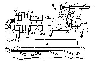
-- The present invention relates to the engine-building
industry and can find application in the fuel feed system of
internal combustion engines for preconditioning part of the
flow of a rich fuel-air mixture fed to the main flow to
decompose liquid fuel and convert it into a gas. A technical
aim of the present invention consists in an increased fuel
economy of the engine, reduced toxicity of exhaust gases, and
use of a cheaper low-octane fuel. A method for preparing
fuel-air mixture consists in that the flow of an overrich
fuel-air mixture is additionally heated, before mixing it with
the other flow of fuel-air mixture, by passing it through a
promoter heated above the mixture ignition temperature, thus
providing repeated contact of the flow with the promoter
surface. A device comprises a heat-exchanger 1 communicating,
via an intake piping 3, with the engine exhaust manifold, a
proportioner 5 of the components of the fuel-air mixture being
handled provided with an air piping 6, an exhaust gas piping
7, and a fuel piping 8. The proportioner 5 communicates, via a
control member 10 and a mixing nozzle 9, with the inlet
mixture-handling loop of the heat-exchanger 1. A promoter 12
is provided in the heat-exchanger outlet nozzle, arranged in a
spaceless relation thereto and being in fact a heating element
having a well-developed surface and may be variously embodied.
USP # 5,291,870
-- Fuel vaporizing system
Covey, Jr.; Ray M
Abstract
-- A system for providing an air-fuel vapor mixture to
an engine for improving completeness of combustion and also
reducing emissions. The system includes a vaporizer within
which a series of baffles are disposed such that air and fuel
pass along a tortuous passageway defined within the vaporizer.
Exhaust gases provide heat to the vaporizer, and as air and
fuel pass along the passageway of the vaporizer, a homogenous
air-fuel vapor mixture is produced, with the homogenous
mixture exiting the vaporizer being supplied to the engine by
way of an adapter plate assembly. When used with a carburetor,
the adapter plate is disposed between the carburetor and the
engine.
USP # 5,247,909
-- Combustion enhancement system
Simmons; William
R
Abstract
-- An apparatus and method for enhancing the efficiency
of a combustion process and thereby reducing undesirable
emissions in which a solid combustion enhancing substance is
converted into a highly dispersed, gas-transportable state at
a controlled rate and is subsequently conveyed into the zone
of combustion. The use of a substance in its solid state eases
handling and avails highly effective materials for combustion
and enhancement while the necessary conversion of the
substance from one state to another enables a high degree of
control as to its rate of addition to the combustion process.
The substance's highly dispersed state when it enters the
combustion process maximizes its effect.
USP # 5,218,944
-- Fuel preheating system for internal combustion engines
Leonard; Paul D.

Abstract
-- A fuel preheater for use with internal combustion
engines is disclosed. The preheater works on the principle
that by preheating the fuel, the fuel is more effectively
vaporized, resulting in more efficient combustion. This
preheating is accomplished using heat normally wasted via the
radiator. The preheater has a housing, through which heated
engine coolant on its way from the engine block to the
radiator is routed. A coiled steel gas line is routed through
the housing, and is connected between the regular fuel line
and the engine.
USP # 5,146,897
-- Intake manifold of intake system for multi-cylinder
internal combustion engine
Hattori;
Toshihiko, et al.

Abstract
-- An intake manifold for a multi cylinder internal
combustion engine has a common upstream passage and individual
downstream passages, leading individually to cylinders of the
engine, respectively. These individual downstream passages are
connected between a downstream end of the common upstream
passage and the cylinders. Upstream end portions of the
individual downstream passages are symmetrically located
around a fuel injector, disposed downstream relative to the
common upstream passage, and are joined together. At a center
of the symmetrically joined upstream end portions of the
individual downstream passages, fuel passages are provided to
open independently into the upstream end portions so as to
introduce fuel from the fuel injector into the individual
downstream passages.
USP # 5,154,154
-- Intake device for a mixture-compressing
internal-combustion engine
Henke; Jurgen, et
al.

Abstract
-- An intake device for a mixture-compressing
internal-combustion engine has a heating element for heating
the injected fuel downstream of an injection nozzle in the
intake channel in order to avoid formation of fuel condensate
which is harmful in the exhaust emission. The heating elements
are configured in plate form and directed at an angle towards
the injected fuel jet such that, on one hand, there is a good
heating and, on the other hand, there is a low flow resistance
by the heating elements. The plate heating element can be
integrated in a flush and heat-insulating manner in the wall
of the intake channel. By virtue of the low flow resistance
which a plate-like heating element arranged obliquely in the
fuel/air mixture flow produces, the heating surface can be
made larged and consequently a rapid fuel heating can be
achieved.
USP # 5,140,966
-- Carburetor for an internal combustion engine
Wong; Men L.

Abstract
-- Carburetors and fuel injection systems are used to
facilitate a combustile mixture of air and fuel for internal
combustion engines. Inherently, the fuel in this mixture is
mostly in liquid droplets. However, it is the vaporous fuel
which combines with the air gives an explosive mixture; and it
is this mixture that can be exploded during the short engine
power stroke time available. The rest of the fuel in liquid
form simply burns or exhausts to the environment, hence
impairing the efficiency of the engine and polluting the
environment. In this invention, liquid fuel is vaporized and
combined with air to form an explosive mixture before
introduction into the engine. In this design, ultrasonic
technology is employed to atomize the fuel in the form of fine
fuel mist. This mist is then injected into a specially
designed heat exchanger, in which hot engine exhaust gas is
brought in to cause this subspension of fuel mist to vaporize.
Subsequently, this vaporized fuel combines with the intake air
to form an explosive mixture. In this process, microcomputer
technology is employed to control the precise air to fuel
ratio of the mixture according to the degree of fuel
vaporization and the demand of the engine operation. The fuel
in this mixture is in a vaporous state; therefore utilization
of the fuel is maximized.
USP # 5,134,986
-- Internal combustion engine with fuel heater
Curhan; Jeffrey
A.

Abstract
-- An internal combustion engine has a channel member
such as a plenum chamber or cylinder head or the like with an
inlet receiving air and fuel to form an air-fuel mixture and
with a pair of outlets furnishing the air-fuel mixture to
respective cylinders or groups of cylinders or to respective
cylinder intake valve openings of two-intake engine cylinders
or the like. A heating device mounted on the channel member
has a heat-exchange surface which intercepts the air and fuel
from the inlet to heat and fully vaporize the fuel to form the
air-fuel mixture and also to divide the fuel mixture between
the two outlets for furnishing the fuel mixture to the
individual cylinders, groups of cylinders or intake valve
openings.
USP # 5,123,398
-- Carburetion system
Klaus; Rudolph W.
& Knowlton; James L.

Abstract
-- A fuel gasifier for an internal combustion engine
having a gasification chamber, a device for injecting fuel
into the chamber in droplets of about 30-50 microns or less in
diameter, an ambient air inlet to the chamber with a flow
control therefor, to admit a controlled amount of ambient air
to mix with the fuel, a heater in the chamber to elevate the
fuel temperature and convert the fuel to a gaseous state, a
fuel and air mixing and transfer impeller in the chamber for
increasing turbulence and propelling the mixture from the
chamber, an annular venturi flow passage for flow of
additional ambient air past the outside of the chamber, and a
plurality of radial passages between the chamber and the
venturi passage for flow of the turbulent mixture into the
venturi passage and entrainment of the fuel and air mixture
into the additional ambient air.
USP # 5,101,801
-- Method of heating an IC engine
Schatz; Oskar

Abstract
-- A method of heating an internal combustion engine
during cold start-up and also for maintaining an optimum
development of the temperature of the combustion gas during
other operational conditions is disclosed. Heat stored in a
heat storage means is released to the combustion air prior to
the entry of same into the combustion chamber of the engine.
USP # 5,086,748
-- Fuel supplying system for gas engine
Yokoyama;
Yoshiharu

Abstract
-- Several embodiments of gaseous fuel supplying systems
for an internal combustion engine used to power a portable
generator. In each embodiment, heat is supplied to the fuel so
as to maintain the fuel pressure if the fuel pressure falls
below a predetermined pressure. In some embodiments, the heat
supply is on-off and in other embodiments it is variable. In
certain embodiments, the heat is supplied electrically and in
another embodiment, the heat is extracted from the engine. In
addition, one embodiment incorporates a cold starting
arrangement wherein fuel is supplied to the engine for cold
starting at full container pressure.
USP # 5,086,747
-- Internal combustion engine with fuel heater
Curhan; Jeffrey
A.

Abstract
-- An internal combustion engine has a channel member
such as a plenum chamber or cylinder head or the like with an
inlet receiving air and fuel to form an air-fuel mixture and
with a pair of outlets furnishing the air-fuel mixture to
respective cylinders or groups of cylinders or to respective
cylinder intake valve openings of two-intake engine cylinders
or the like. A heating device mounted on the channel member
has a heat-exchange surface which intercepts the air and fuel
from the inlet to heat and fully vaporize the fuel to form the
air-fuel mixture and also to divide the fuel mixture between
the two outlets for furnishing the fuel mixture to the
individual cylinders, groups of cylinders or intake valve
openings.
USP # 5,048,501
-- Fuel economy system for internal combustion engines
Smith; Dale T.
& Amistadi; C. George

Abstract
-- A mechanical process for significantly improving the
octane rating performance of gasoline powered engines (either
conventional carburetion or fuel injection). An auxiliary
system fractionates a precise portion of the required fuel and
combines the fraction thus formed with a conventionally
produced air/fuel mixture in states and proportions which
optimize the combustion process. Different means of
implementing the process are described utilizing an additional
fuel controller which is connected to a fuel supply through an
existing fuel pump which delivers fuel to both the fuel
controller and an existing carburetion of fuel-injection
system. Air for both is drawn through a common air filter. A
proportioning system determines the proper amount of air and
fuel entering the controller where they are mixed. The vapor
fraction is enhanced and stabilized by passing the mixture
through a heat exchanger. This vapor-rich mixture is then
combined with the air/fuel mixture supplied by the existing
system, and introduced into the engine's manifold. Precise
control of the vapor fraction permits highly efficient
combustion heretofore attainable only with chemical additives,
such as tetraethyl lead.
USP # 5,042,447
-- Thermostatically controlled fuel heater and cooler
Stone; Walter H.

Abstract
-- A device for heating and cooling fuel to maintain the
temperature of fuel delivered to an engine within a desired
temperature range includes a body (10) having a fuel inlet
(12) and a fuel outlet (14). The body includes a middle
portion (16) and a first heat exchanger portion (18) in
connection with a heat source. The body also includes a second
heat exchanger portion (20) in connection with a heat sink. A
thermostatic actuator (86) positioned adjacent the outlet of
the device, includes a plunger rod (88) that extends
responsive to increased temperature of the fuel passing the
actuator. A movable member (74) is positioned by the plunger
rod to direct fuel to either a first opening (28) from which
the fuel passes through the first heat exchanger portion and
is heated, or to a second opening (30) from which the fuel
passes through the second heat exchanger portion and is
cooled. Fuel passing through the device is divided between the
first and second heat exchanger portions to maintain the fuel
delivered from the device within the desired temperature
range.
USP # 5,040,518
-- Fuel vaporizer manifold
Hamm; Myrle W.

Abstract
-- A fuel vaporizer manifold to be mechanically
interconnected between the carburetor and intake manifold of
an internal combustion engine of a motor vehicle. The
vaporizer manifold comprises a plurality of parallel aligned
and longitudinally extending heating tubes and a plurality of
parallel aligned and laterally extending heat conducting fins
that are arranged in thermal contact with said tubes. A
portion the hot exhaust gases being emitted from the engine is
recycled from the exhaust manifold to the carburetor by way of
the heating tubes of the vaporizer manifold to thereby heat
the tubes and the fins in contact therewith. Liquid fuel (e.g.
gasoline), which is mixed with air and supplied to the
vaporizer manifold from the carburetor, flows over the heat
conducting fins, whereby said liquid fuel is vaporized. The
vaporized fuel is supplied from the vaporizer manifold to the
intake manifold to be efficiently combusted within the
cylinders of the engine. Accordingly, the exhaust emitted into
the atmosphere by the engine will be characterized by a
relatively low temperature and less potentially harmful
pollutants.
USP # 5,040,517
-- Carburetor preheater
Cox; Carl C.

Abstract
-- A continuous hot air intake for carburetor and fuel
injection supplied engines that regulates the temperature of
air mixing with fuel that is mixed in the carburetor or fuel
injector prior to introduction to the cylinders of the engine.
The invention includes preferably a heater and associated
filter located at the air intake side of the carburetor that
is activated by circulating heated fluid contained within the
engine cooling system. The heater, in preferred form, is
conveniently sized and circular in configuration so as to
encircle the filter positioned at the air intake side of the
carburetor, however, a circular filter can be used to encircle
the heater. The heater and filter are encompassed by a
releasably securable cover to hold these components together
and in place and to block the entry of dust, dirt or other
invading elements.
USP # 5,038,742
-- Vaporizer nozzle
Uddin; Mustafa A.

Abstract
-- A vaporizing nozzle which comprises a wall (16) of
porous material through which a liquid to be evaporated
percolates from one side thereof into a gas stream at the
other side thereof and a thermoelectric device (30) located at
or adjacent the wall of porous material whereby to regulate
the temperature thereof. A computer is provided, with a read
only memory (ROM) or equivalent containing a "map" of the air
to fuel ratio required for given values of the various
parameters and compares the sensed values with the map held in
memory and sends an appropriate signal to thermoelectric
device controller which responds by sending a current of the
correct magnitude and polarity to the device such that the
device, which is in close proximity to the wall heats or cools
the surface of the wall to a desired level thus regulating the
flow or fuel therethrough.
USP # 5,027,759
-- Fuel injection and gasifying system for two-stroke engine
Luo; Jih-Tzang

Abstract
-- A fuel injection and gasifying system for an internal
combustion engine is disclosed. The combustion system includes
a piston assembly with a piston furnished with a gasifying
chamber, a cylinder which contains the combustion apparatus, a
crank assembly with a crankcase, an injection apparatus, and a
control apparatus. The crank assembly manipulates the piston
assembly between a first position and a second position. The
injection apparatus delivers a fuel mixture to the combustion
system, and is positioned such that, when the piston assembly
is in the first position, the injection apparatus opens into
the gasifying chamber, and when the piston assembly is in the
second position, the injection apparatus opens into the
crankcase. The control apparatus controls the operation of
injection apparatus. When the temperature of the gasifying
chamber is below the vaporizing temperature of the fuel the
fuel is injected into the crankcase. Once the gasifying
chamber has reached the vaporizing temperature, the fuel is
injected into the gasifying chamber.
USP # 5,019,120
-- Vapor-accelerated combustion fuel system
Lewis; Alfred M.
& Cox; James W

Abstract
-- The invention produces and meters a constant supply
of volatile gasoline vapors into the cylinders of an internal
combustion gasoline engine. The vapors are produced by
releasing them from liquid gasoline through pressure
differential inside a closed vaporizer container. Vapor is
transferred from the container to the fuel delivery mechanism
by introducing the vapor into one or more constant vacuum
inlet ports of the fuel delivery mechanism. A variable gascock
valve regulates the flow of vapor. These constant vacuum inlet
ports, and lines thereto, are standard components of all
modern automobile engines and require no modification for
installation of the invention. All gasoline burned by the
engine first passes through the system's vaporizer container
where a portion of the available vapor (free vapor) is
released and transferred to the fuel delivery mechanism.
Unvaporized liquid gasoline within the container is
concurrently pumped to the fuel delivery mechanism by an
auxiliary fuel pump.
USP # 5,012,788
-- Fuel-air mixture-forming device for internal combustion
engines
Feldinger, Martin

Abstract
-- The present invention proposes a fuel-air
mixture-forming device for internal combustion engines, having
a rotationally symmetric nozzle body (2) which, together with
a rotationally symmetric throttle body (8) displaceable in it,
forms a convergent-divergent nozzle which discharges into a
radial diffusor (6). In the vicinity of the narrowest cross
section (5) of the nozzle there is provided a fuel slot (11)
extending around it and discharging into it, at least one fuel
feed line (9, 10) discharging into the fuel slot. The radial
diffusor is formed by a region of the nozzle body which is
curved outward in the direction of flow of the mixture and by
a wall (15) of a structural member (17) which forms a
structural unit (18) with an intake manifold (7) of the
internal combustion engine, the wall (15) lying opposite the
nozzle body and being rotationally symmetric to the
longitudinal axis (1) of the throttle member and having a
bulge (16) pointing toward the throttle member. Due to its
development, the radial diffusor makes it possible that a film
of fuel which necessarily adheres to the diffusor wall upon
injection of the fuel detaches itself, whereby an improved
mixture is formed.
USP # 4,984,555
-- Diesel engine fuel pipeline heating device
Huang, Kuo-Liang

Abstract
-- The present invention is related to a diesel engine
fuel pipeline heating device and particularly to a diesel
engine fuel pipeline heating device consisting of an electric
heating device and a water (or air) temperature heating device
provided to the exterior of diesel engine fuel pipe. A diesel
engine equipped with such a heating device can be easily
started through the electric heating device to heat the fuel
in the fuel pipe up to a suitable starting temperature around
40.degree. C. (or 104.degree. F.) before starting the engine;
and after starting the engine for some time, namely, when the
temperature in the heating cylinder of water (or air) heating
device has risen to the said suitable combustion temperature
around 40.degree. C. (or 104.degree. F.), the power source of
electric heating device is automatically turned off to stop
the heating action. Then the hot water from the water return
pipe of radiator or the hot air from the exhaust pipeline of
exhaust pipe keeps continued preheating of fuel pipe for a
constant temperature through the water (or air) heating device
so as to continuously keep the full fuel combustion, easily
and smoothyl start and run the engine, save fuel and enhance
the horse power of engine.
USP # 4,979,483
-- Diesel fuel heater
Ray, Dennis A.

Abstract
-- A diesel fuel heater for heating diesel fuel prior to
its introduction into the diesel engine wherein said fuel
heater comprises top and bottom covers and an elongate annular
section. The fuel heater of the present invention heats the
fuel by passing engine coolant across fuel carrying fuel tubes
located in the heat transfer chamber.
USP # 4,971,018
-- Diesel fuel heater
Ray, Dennis A.

Abstract
-- A diesel fuel heater for heating diesel fuel prior to
its introduction into the diesel engine wherein said fuel
heater comprises top and bottom covers and an elongate annular
section. The fuel heater of the present invention heats the
fuel by passing engine coolant across fuel carrying fuel tubes
located in the heat transfer chamber.
USP # 4,955,351
-- Vapor-accelerated combustion fuel system
Lewis, Alfred M.
& Cox, James W.

Abstract
-- The invention produces and meters a constant supply
of volatile gasoline vapors into the cylinders of an internal
combustion gasoline engine. The vapors are produced by
releasing them from liquid gasoline through pressure
differential inside a closed vaporizer container. Vapor is
transferred from the container to the fuel delivery mechanism
by introducing the vapor into one or more constant vacuum
inlet ports of the fuel delivery mechanism. A variable gascock
valve regulates the flow of vapor. These constant vacuum inlet
ports, and lines thereto, are standard components of all
modern automobile engines and require no modification for
installation of the invention. All gasoline burned by the
engine first passes through the system's vaporizer container
where a portion of the available vapor (free vapor) is
released and transferred to the fuel delivery mechanism.
Unvaporized liquid gasoline within the container is
concurrently pumped to the fuel delivery mechanism by an
auxiliary fuel pump.
USP # 4,883,616
-- Vaporizer/carburetor and method
Covey, Jr., Ray
M.

Abstract --
A vaporizer unit has an enclosing casing including a plurality
of tubes therein, defining a fuel passage therethrough,
including the tubes. The tubes have coiled wire screen
therein. An auxiliary carburetor is positioned at the inlet
end of the fuel passage, and an outlet passage leads to the
main carburetor of the automobile. The casing also defines an
exhaust passage therethrough, transversely of the fuel
passage, providing heat transfer between the exhaust gases and
the tubes. The temperature of the resulting vaporized fuel is
sensed for varying the flow of the exhaust gases and thereby
controlling the temperature of the vaporized fuel, which is
maintained at 250.degree. F. to 260.degree. F. An electric
crystal is used for breaking down the heavy ends of the fuel.
The rate of flow of air to the main carburetor is varied for
correspondingly varying the rate of intake of vaporized fuel
from the vaporizer unit. Automatic and manual controls are
both utilized selectively, each without interfering with the
other.
USP # 4,883,040
-- Fuel vaporizer
Rocky, William C.

Abstract --
The invention relates to a method and system for increasing
the output in terms of miles per gallon attainable by a
conventional internal combustion engine. The improvement in
m.p.g. is the result of a fuel vaporizer unit which utilizes
engine collant and exhaust gases in heat exchange relationship
to vaporize raw fuel. The gas vapors are collected within the
vaporizer unit and then directed to the carburetor wherein it
is united with air prior to entering the intake manifold. It
has been found that running an engine on a mixture of gas
vapors and air produces significantly improved mileage over
that otherwise attainable. An additional advantage of the
vaporizer unit is the resulting reduction of the amount of
pollutants released into the atmosphere due to the complete
and total combustion of all the vapors entering the combustion
chambers.
USP # 4,862,859
-- Apparatus and operating method for an internal combustion
engine
Yunick, Henry

Abstract
-- A method and apparatus for operating an electric
ignition, internal combustion engine that substantially
improves the fuel efficiency by utilizing heat normally
discharged to the ambient to condition and prepare the fuel
mixture prior to entry into the combustion chambers. The
apparatus comprises a fuel vaporizer that transfers heat from
the engine coolant system to the fuel mixture as it leaves a
fuel introducing device such as a carburetor; a fuel mixture
heater for heating the mixture above the vaporization
temperature of the liquid fuel; and, a mixture homogenizer for
thoroughly stirring the fuel mixture that is located in the
fuel mixture flow path intermediate the vaporizer and heater.
The homogenizer is operative to compress the fuel mixture
under certain engine operating conditions and the heater forms
the intake manifold for the engine and includes branch flow
paths and associated conduits that communicate directly with
each combustion chamber through a valve controlled port. The
fuel mixture flow path from the homogenizer is constructed to
minimize energy losses to the ambient.
USP # 4,829,969
-- Spiral distributor fuel heater
Ray, Dennis A.

Abstract
-- A fuel heating device for internal combustion engines
using engine coolant to heat the fuel prior to the
introduction of the fuel into the carburetor and utilizing a
spiral distributor to evenly heat the fuel and eliminate vapor
lock. The spiral distributor provides a means for spiraling
the fuel through a heat transfer chamber to evenly heat the
fuel and decrease the amount of vaporized fuel created by
heating the fuel.
USP # 4,768,493 --
Blow-by gas heating system for internal combustion engines
Ohtaka, Shoichi

Abstract
-- An arrangement for heating the blow-by gas system of
a water cooled type internal combustion engine by providing
engine coolant conduits in heat exchange relationship with the
blow-by gas hoses and PCV valve. In one embodiment a water
jacket surrounds the PCV valve. The heat exchangers between
the blow-by gas system hoses and the coolant hoses are
parallel adjacent conduits in one embodiment and concentric
conduits in another embodiment.
USP # 4,718,393
-- Air-fuel homogenizer
Bakish, Richard
J.

Abstract
-- A device for increasing the homogenity of the
air-fuel stream between the carburetor and the intake manifold
of an internal combustion engine. A first cylindrical member
is connected between the carburetor and intake manifold, said
first cylindrical member having within it multiple sets of
vanes for mixing the gaseous stream flowing within. Means for
controlled heating of the gaseous stream moving through the
first cylindrical member is provided. Means for driving the
gaseous stream through the first cylindrical member is also
provided.
USP # 4,708,100
-- Two-stroke engine with injected fuel gasifying chamber in
piston
Luo, Jih-Tzang

Abstract
-- It is a reciprocating type of internal combustion
engine, of which the inside of piston is furnished with a
gasifying chamber; the outlet of the gasifying chamber can,
during the piston moving reciprocatingly, be in alignment with
the spraying nozzle on the cylinder and the third scavenging
passage in sequence so as to let the spraying nozzle directly
spray fuel into the gasifying chamber, and to let the fuel
absorb the high temperature heat of the piston top to cause
the fuel to be gasified completely. The gasified fuel flows
into the third scavenging passage during the piston moving
downwards and is to be stored therein temporarily; then, the
gasified fuel is compressed into the cylinder by means of the
compressed air in the crankcase so as to mix with the fresh
air entered into the cylinder via other scavenging passages.
The gas mixture is to be compressed with the upward moving
piston, and to be exploded to generate a mechanical power.
USP # 4,671,245
-- Throttle valve pipe
Knapp, Heinrich

Abstract
-- A throttle valve pipe is proposed, which is used for
fuel mixture formation for mixture-compressing internal
combustion engines with externally supplied ignition. The
throttle valve pipe includes an intake conduit and a throttle
valve is disposed therein and to control fuel flow. From
upstream of the throttle valve fuel can be ejected by an
injection valve in the direction toward the throttle valve.
The throttle valve is made of ceramic and on its surface which
faces the injection valve this valve is provided with an
electric heating resistor film. In the pivoting region of the
throttle valve, a liner of ceramic is inserted into the intake
conduit and the additionally liner surface which forms part of
the intake conduit is provided with an electric heating
resistor film.
USP # 4,667,643
-- Heated fuel vapourizer and slidable throttle valve
Arnold, Bruce M.

Abstract
-- Apparatus for supplying a gaseous fuel mixture to a
combustion chamber. A fuel vaporizer vaporizes liquid fuel
which is then mixed with air. The vaporizer and mixing chamber
are heated to maintain the temperature of the vaporized
fuel/air mixture. The vaporizer and mixing chamber are also
interconnected so that vaporized fuel is discharged directly
from the vaporizer into the mixing chamber. A simplified valve
for controlling the quantity of vaporized fuel discharged into
the mixing chamber is provided.
USP # 4,651,702
-- Air-fuel mixture heating device for internal combustion
engine
Nara, Akio, et
al.

Abstract
-- A heating device for heating air-fuel mixture to be
fed to an internal combustion engine has a PTC heat generator
having a flat ring-like form with a portion of the inner
peripheral surface thereof directly exposed to the passage for
the mixture. The heating device also has a heat radiating
member having an inner peripheral heat radiating surface
confronting the mixture passage and jointed to the PTC heat
generator in heat conducting relation therewith.
USP # 4,637,365
-- Fuel conditioning apparatus and method
Yunick, Henry

Abstract
-- A method and apparatus for operating an internal
combustion engine that substantially improves the fuel
efficiency by utilizing heat normally discharged to the
ambient to condition and prepare the fuel mixture prior to
entry into the combustion chambers. The apparatus comprises a
fuel vaporizer, a fuel mixture heater and a mixture
homogenizer located in a fuel mixture flow path intermediate
the vaporizer and the heater. The fuel vaporizer includes
structure defining an inner heat exchange chamber which
receives air and entrained fuel discharged by a fuel
introducing device such as a carburetor. The fuel mixture is
heated and at least partially vaporized by engine waste heat
derived from the engine cooling system or alternately the
engine exhaust system. To facilitate the transfer of heat to
the fuel mixture, a pair of heat exchange members are disposed
in the chamber and include a supply tube defining a flow path
for fluid carrying engine waste heat and a plurality of
bristle-like heat exchange surfaces radiating outwardly from
the supply tube. The bristle-like surfaces are located in heat
exchange relation with the fuel mixture in the vaporizing
chamber and transfer heat from the heat exchange fluid to the
fuel mixture as the fuel mixture passes through the vaporizer.
USP # 4,611,567
-- Vaporizer/carburetor
Covey, Jr., Ray
M.

Abstract
-- A vaporizer unit has an enclosing casing including a
plurality of tubes therein, defining a fuel passage
therethrough, including the tubes. The tubes have coiled wire
screen therein. An auxiliary carburetor is positioned at the
inlet end of the fuel passage, and an outlet passage leads to
the main carburetor of the automobile. The casing also defines
an exhaust passage therethrough, transversely of the fuel
passage, providing heat transfer between the exhaust gases and
the tubes. The temperature of the resulting vaporized fuel is
sensed for varying the flow of the exhaust gases and thereby
controlling the temperature of the vaporized fuel, which is
maintained at 250.degree. F. to 260.degree. F. An electric
crystal is used for breaking down the heavy ends of the fuel.
The rate of flow of air to the main carburetor is varied for
correspondingly varying the rate of intake of vaporized fuel
from the vaporizer unit. Automatic and manual controls are
both utilized selectively, each without interfering with the
other.
USP # 4,603,672
-- Fuel vaporizer for internal combustion engine
Keller, R. W.

Absract --
Pre-cooled aerosol spray fuel/air mixture is discharged
through an array of metering tubes which are housed within a
heat exchange chamber. Engine coolant is circulated through
the heat exchange chamber. As the aerosol fuel/air mixture is
drawn from the carburetor through the metering tubes and into
the manifold, heat transfer from engine coolant circulating
through the heat exchange chamber causes the aerosol mixture
in the metering tubes to vaporize. In a preferred embodiment,
the temperature rise within the heat exchange chamber is
limited by heat transfer to an air circulation tube which is
coiled within the heat exchange chamber.
USP # 4,593,670
-- Fuel evaporator for internal combustion engine
Nara, Akio, et
al.

Abstract
-- A fuel evaporator comprises a ring-shaped heater
element made of PTC ceramic, a pipe made of heat conductive
metal and disposed within an air-fuel passage of an internal
combustion engine therealong and a pair of terminal members
for supplying power to the heater element. The heater element
is disposed closely in contact with the outer periphery of the
upper end of the pipe. One end of each of the pair of terminal
members is closely in contact with each of the upper and under
surfaces of the heater element. The fuel evaporator further
comprises a plate-shaped compact made of electricity
insulating rubber or synthetic resin and formed around the
upper end of the pipe. Within the compact, the heater element,
the upper end of the pipe and the terminal members are
embedded.
USP # 4,592,329
-- Apparatus and operating method for an internal combustion
engine
Yunick, Henry

Abstract
-- A method and apparatus for operating an electric
ignition, internal combustion engine that substantially
improves the fuel efficiency by utilizing heat normally
discharged to the ambient to condition and prepare the fuel
mixture prior to entry into the combustion chambers. The
apparatus comprises a fuel vaporizer (50) that transfers heat
from the engine coolant system to the fuel mixture as it
leaves a fuel introducing device such as a carburetor (38); a
fuel mixture heater (52) for heating the mixture above the
vaporization temperature of the liquid fuel; and, a mixture
homogenizer (54) for thoroughly stirring the fuel mixture that
is located in the fuel mixture flow path intermediate the
vaporizer and heater. The homogenizer is operative to compress
the fuel mixture under certain engine operating conditions and
the heater forms the intake manifold for the engine and
includes branch flow paths (152a) and associated conduits
(164) that communicate directly with each combustion chamber
(32) through a valve controlled port (34a). The fuel mixture
flow path from the homogenizer is constructed to minimize
energy losses to the ambient.
USP # 4,583,511
-- Carburetion apparatus
Greene, Harry E.

Abstract
-- The invention comprises a carburetion apparatus for
use with an internal combustion engine having a generally
conventional carburetor, an intake manifold and an exhaust
manifold. The carburetion apparatus has a central chamber that
receives the fuel-air mixture from the carburetor and delivers
the fuel-air mixture to the intake manifold. The central
chamber is provided with baffles to divert the fluid flow and
cause intimate mixing of fuel and air. The baffles are such
that the manifold vacuum is raised (or, the pressure is
lowered), so the vacuum assists in evaporating liquid fuel.
The baffles may be heated by passing exhaust gases through
them, the exit of the exhaust gas being slowed by a
constricted outlet.
USP # 4,579,163
-- Heat exchanger core and air flow control
Maendel, Jonathan
P.

Abstract
-- A heat exchange apparatus includes a core mounted
within a casing and two fans arranged to draw air from the
exterior of a building through the core in a first path and to
draw air from the interior of the building through the core in
a second path. The core is made up from a plurality of tubular
cells each formed from a single folded sheet of aluminum and
having a slot shaped cross section. The short sides of the
slot are arranged to face the inlet of cold exterior air so
that it impinges upon the outer surface of the short side. The
fan drawing the warm air is arranged to direct air onto the
other surface of the short side so that the short side and the
surrounding portions of the long sides act as an effective
heat exchange surface free from the seam of the tubular core
which is arranged adjacent opposite the short side. A
differentially perforated baffle plate spreads the cold air
over core such that more cold air is directed to the warm end
of the core. The amount of warm air passing through the core
is arranged to be greater than the amount of cold air so as to
maintain the core above frosting temperatures. The excess of
air can be arranged by bypassing air to and from the interior
of the building through openings in the casing.
USP # 4,574,764
-- Fuel vaporization method and apparatus
Earle, John L.

Abstract
-- Carburetor air-fuel mixtures are directed to a
manifold having a plurality of long, small diameter helical
tubes extending upwardly therefrom. An auxiliary air inlet
having an auxiliary choke and an auxiliary air throttle
supplies air to mixtures entering the tubes in response to
engine temperature and carburetor throttle. Heated engine
coolant flows upwardly through a jacket enclosing the tubes.
An outlet manifold receives air-fuel mixtures vaporized in the
tubes and directs them to the engine intake manifold. The
carburetor is mounted on a block having an air-fuel passageway
extending from a top inlet to a side outlet. The block is
mounted atop a block having a passageway having a side inlet
which receives vaporized air-fuel mixtures from the tubes to a
bottom outlet in communication with the intake manifold.
USP # 4,548,183
-- Operational mode responsive heating arrangement for
internal combustion engine induction system
Hayashi,
Yoshimasa

Abstract
-- In an engine system wherein the engine coolant is
permitted to boil and the gaseous coolant used as a vehicle
for removing heat from the engine, a heating jacket associated
with the induction conduit of the engine is supplied with
gaseous coolant via a control valve during cold engine starts
and during modes of engine operation wherein it is
advantageous from the view point of fuel economy to raise the
temperature of the engine and/or the incoming fuel charge. The
supply is terminated under other modes of operation to avoid
heating the incoming charge and reducing charging efficiency.
USP # 4,534,333
-- Internal combustion engine with air-fuel mixture heating
Slattery, Gordon
C.

Abstract
-- An internal combustion engine (1) includes a
supplemental fuel passage (26, 27) which connects the
carburetor (9) to the exhaust chest cover (28). A supplemental
air inlet having a metering orifice (36) and passage (35)
connects to the supplemental fuel passage. The resultant
air-fuel mixture is heated before entry into the combustion
chamber by passing the mixture through a heating passage (32)
directly in front of the exhaust ports (13). When the engine
is at idle with a completely closed throttle valve (19), the
entire air-fuel supply for the engine is provided through the
supplemental fuel and air passages and is heated in the
heating passage prior to combustion. At increasingly open
throttle, air-fuel is increasingly provided from the
conventional primary carburetor output, with the heated
air-fuel mixture being supplied in gradually decreasing
amounts.
USP # 4,524,746
-- Closed circuit fuel vapor system
Hansen, Earl S.

Abstract
-- A closed circuit vapor system wherein liquid is
introduced to an ultrasonic transducer in a vaporizing chamber
where it is vaporized and drawn into a preheater chamber and
then drawn off by a pump and recirculated back to pass through
the heater chamber. In one embodiment, it jets through a
venturi to draw off more vapor from the vaporization chamber
for heating and recirculation. The dry vapors are drawn off
only as needed to meet the engine demands.
USP # 4,513,698
-- Intake manifold structure for internal combustion engines
Senga, Akihisa,
et al.

Abstract
-- An improved intake manifold structure for internal
combustion engines includes a distribution chamber having an
upper sub-chamber leading to a carburetor and a lower
sub-chamber communicating with the upper sub-chamber through a
communication hole. A plurality of branch passages extend from
the lower sub-chamber to a plurality of combustion chambers.
An air-fuel mixture fed from the carburetor to the
distribution chamber is expanded successively in two steps to
promote its atomization as it passes through the two
sub-chambers, thus improving uniform distribution of the
mixture to the respective branch passages. Engine exhaust gas
is returned to the upper sub-chamber to further promote the
atomization of the mixture.
USP # 4,503,833
-- Apparatus and operating method for an internal combustion
engine
Yunick, Henry

Abstract
-- A method and apparatus for operating an electric
ignition, internal combustion engine that substantially
improves the fuel efficiency by utilizing heat normally
discharged to the ambient to condition and prepare the fuel
mixture prior to entry into the combustion chambers. The
apparatus comprises a fuel vaporizer that transfers heat from
the engine coolant system to the fuel mixture as it leaves a
fuel introducing device such as a carburetor; a fuel mixture
heater for heating the mixture above the vaporization
temperature of the liquid fuel; and, a mixture homogenizer for
thoroughly stirring the fuel mixture that is located in the
fuel mixture flow path intermediate the vaporizer and heater.
The homogenizer is operative to compress the fuel mixture
under certain engine operating conditions and the heater forms
the intake manifold for the engine and includes branch flow
paths and associated conduits that communicate directly with
each combustion chamber through a valve controlled port. The
fuel mixture flow path from the homogenizer is constructed to
minimize energy losses to the ambient.
USP # 4,491,552
-- Pressurized/heated variable jet carburetor
Wessel, Tim

Abstract
-- A monolithic variable jet carburetor comprising an
air intake, an associated variable jet and an underlying fuel
reservoir, all contained within a pressurized and heated
chamber and whereby the fuel is injected into the reservoir
under pressure and is atomized via an overlying wire mesh
screen and vaporized as it traverses the remainder of the
heated delivery path to the air intake. The heated chamber is
adapted to heat the fuel at all points intermediate the float
chamber and air intake venturi via hot engine gasses or heated
engine coolant and wherein the float chamber is further
pressurized via an air pump. Pressure/temperature sensors
control the relative ratios thereof during normal engine
cycling under various load conditions.
USP # 4,478,198
-- Fuel treating apparatus for internal combustion engines
Bruhn, Larry C.

Abstract
-- A housing has an inlet arranged to be connected to
the outlet of a fuel mixing device of an internal combustion
engine such as a carburetor and an outlet arranged to be
connected to the intake manifold of the engine. In a preferred
embodiment of the invention, the housing has two or more
spiral bores. These bores have a cross sectional area less
than the cross sectional area of the outlet of the carburetor
to provide increased time and velocity through the spiral
bores and to isolate the carburetor from vacuum pulsations of
the engine. The defining surfaces of the spiral bores is
roughened to increase atomization. A second embodiment
utilizes an elongated housing also having a spiral path for
mixing the fuel and air. This latter housing has a
longitudinal bore which also increases the velocity of flow of
fuel and air mixture through the housing and includes a vacuum
controlled valve arranged upon decreased vacuum to allow
direct flow of fuel to the intake manifold in bypassing
relation for providing a heated area around the spiral path,
such casing being arranged to be connected into the exhaust
manifold for using the heat therefrom.
USP # 4,469,077
-- Fuel mixture method and apparatus for internal combustion
engines
Wooldridge, Bobby
M.

Abstract
-- A housing located between a conventional carburetor
and the intake manifold inlet on a conventional internal
combustion engine (such as that used in an automobile) has
internal compartmentation to receive a volume of fuel and air
mixture from the carburetor and to direct same through an
outlet compartment and thence through a conduit to a fuel
mixture heat exchanger mounted on the engine. The heat
exchanger comprises one or more heat exchanger units each
having a closed cylindrical housing with a plurality of
closed, individual fuel mixture conduits therein (such as
copper tubing). Each cylindrical housing is connected by a
conduit, such as a hose, to the hot air exhaust manifold of
the engine so that the heated air from the manifold is
directed through each housing and around the heat exchanger
tubes therein. A filter unit comprises a closed housing which
receives the heated fuel through a porous screen baffle and a
series of conventional ceramic or foam plastic or other types
of filter material. The method comprises the procedure of
directing the fuel mixture from the carburetor through the
above system and apparatus and back into the engine.
USP # 4,465,053
-- Fuel system having low profile gasket heater
Berg; Peter G.

Abstract
-- A fuel system for an internal combustion engine has
an electrical resistance heater accommodated in low profile
gasket means at a location between a throttle body mounting
flange and a mating intake manifold flange for heating the
throttle body. The gasket means comprises a relatively rigid
electrically insulating spacer forming a chamber, a
heat-transfer member and a terminal secured to opposite sides
of a heater for mounting and making electrical connection to
the heater which is accommodated in the spacer chamber, and
relatively thin outer layers of more compressible gasket
material for sealingly engaging the throttle body and mating
manifold flange means respectively.
USP # 4,463,737
-- Fuel system having gasket heater
Berg, Peter G.
& Strobel, Stephen J

Abstract
-- A fuel system for an internal combustion engine has
an electrical resistance heater accommodated in gasket means
disposed between a throttle body flange and a mating flange on
an intake manifold so that the heater is located immediately
adjacent an idling speed fuel inlet nozzle or the like in the
throttle body for transferring heat to the nozzle area through
the throttle body flange to prevent freeze-up of the nozzle
during engine operation.
USP # 4,438,750
-- Device for fuel delivery to internal combustion engine
with vaporization of injected fuel
Sviridov, Jury
B., et al.

Abstract
-- Disclosed is a device for fuel delivery to an
internal combustion engine, mprising a vaporizing element
whose one section is heated by exhaust gases and the other
section is disposed in an intake duct and has an operating
surface, a fuel charge being injected onto said surface by an
injection nozzle. In this device the operating surface of the
vaporizing element extends from its section heated by the
exhaust gases to a diametrically opposite portion of the
intake duct, and the orifice of the injection nozzle is
directd tangentially as close to the operating surface of the
vaporizing element as possible.
USP # 4,434,772
-- Combustion mixture generator for internal combustion
engines
Hartel, Gunter,
et al.

Abstract
-- A carburettor or other combustible mixture generator
1 has a mixture chamber 3 surrounded by a tubular wall 2 which
has an inner skin 9 and an outer skin 10 with an annular
heating chamber 11 between them. Heating fluid such as exhaust
gas or heated engine cooling water flows through the chamber
11 from an inlet 12 to an outlet 13 and so heats the inner
skin 9. A fuel metering device 6, 7 directs the fuel on to the
surface of the heated skin 9 and thus causes the fuel to be
evaporated within the mixing chamber 3 upstream of a throttle
4. This greatly improves the uniformity of the mixture and the
uniformity of its distribution through an inlet downstream of
the throttle 4.
USP # 4,425,899
-- Intake heating device of an internal combustion engine
Kato, Keigo &
Kuroiwa, Yoshio

Abstract
-- The present invention proposes an intake heating
device of an internal combustion engine. The intake heating
device has a hollow heater vessel comprising an inner pipe and
an outer pipe between which an enclosed area is defined. For
heating the inner pipe, a plurality of PTC elements are
disposed in said enclosed area. The protection of the PTC
elements from water, oil and the like is accomplished by
coupling the inner and outer pipes hermetically and by
embedding the lead members for applying voltage to PTC
elements integrally in the outer pipe wall when it is being
cast. For maintaining the fundamental function of the PTC
elements, at least one of the lead members embedded in the
pipe wall is formed in a tubular shape along which a through
hole can be provided for allowing a certain amount of air to
flow into said enclosed area.
USP # 4,420,439
-- Constant pressure carburettors
Hartel, Gunter,
et al.

Abstract
-- A downdraught carburettor of the constant pressure
type has a mixing chamber 2 with an operator-controlled
throttle valve 3 at its downstream end and a choke valve 10,
which is operated by a diaphragm box 20 in dependence upon the
pressure in the mixing chamber 2, at its upstream end. Fuel is
supplied to the mixing chamber from an annular duct 5 through
ports 6 to the wall of the mixing chamber down which the fuel
flows in the form of a thin film. The film is evaporated to
form the mixture by a heating jacket 16 which surrounds the
mixing chamber 2 and is heated by engine cooling water or
exhaust gases. In order to prevent the film of fuel from being
broken up before it has been heated and evaporated, which
tends to happen owing to turbulence in the air stream caused
by the choke valve 10, an inner tube 11 is provided. The choke
valve 10 is situated in the upstream end of the inner tube 11
so that the fuel film is screened by the tube 11 from any
turbulence caused by the valve 10. Air flow to draw fuel from
the ports 6 and build up the film on the wall of the mixing
chamber takes place through narrow annular ducts 12 between
the tube 11 and the surrounding mixing chamber wall, these
narrow ducts being uniformly spaced apart around the whole of
the outside of the tube 11.
USP # 4,399,794
-- Carburetion system
Gagnon, David C.
Abstract
-- This carburetion system for automobiles serves to
increase gasoline mileage greatly, and it consists primarily
of a regulator for metering drops of fuel onto a motor-driven
fan in a fuel and air mixing chamber. It further includes a
heat expansion cylinder connected to the mixing chamber, so as
to vaporize the mixture fully and completely by exhaust gases
of the engine, prior to the fuel and air gas entering the
cylinders of the automobile engine.
USP # 4,388,910
-- Intake expansion chamber apparatus for internal
combustion engines
Birdwell, Glenn
E.

Abstract
-- An intake expansion chamber apparatus (10) for
internal combustion engines is disclosed which preheats and
expands the vaporized fuel/air mixture as the mixture flows
between the carburetor and the combustion chamber. The
apparatus includes an expansion chamber section (18) through
which the fuel/air mixture flows between an inlet (20)
connected in fluid communication with the intake manifold and
an outlet (26) joined in fluid communication with the intake
manifold at a location downstream from the outlet. The
fuel/air mixture is heated during its passage through the
expansion chamber by a heat transfer surface (30) to improve
the vaporization and to more completely combust the
hydrocarbons upon ignition. A safety valve (46) is provided to
release pressure built up within the expansion chamber as
during an engine backfire.
USP # 4,379,770
-- Carburetors for internal combustion engines
Bianchi, Valerio

Abstract
-- A constant pressure carburettor comprises a mixing
chamber 2 which is surrounded by a heating jacket 12, an
operator controlled throttle valve 3 at the downstream end of
the chamber 2, a fuel feeder 5, 6 at the upstream end of the
mixing chamber and a choke valve 10 at an air inlet to the
carburettor. The choke valve 10 is, in use, controlled
automatically by the air flow into the carburettor in
dependence on the opening of the throttle valve 3 and the
speed of the engine to which the carburettor is fitted. The
choke valve 10 tends to produce vortices or turbulence in the
air flow and this tends to cause the fuel supplied by the
feeder 5, 6 to the wall of the chamber 2 to be prematurely
removed before it is heated. This adversely affects the
vaporization of the fuel and the formation of the air-fuel
mixture. To avoid turbulence or vortices in the chamber 2, a
stabilization conduit 16 is provided between the choke valve
10 and the fuel feeder 5, 6. The conduit 16, which preferably
has two right-angle bends as shown, damps out or at least
decreases the vortices or turbulence in the air flow before it
reaches the mixing chamber 2.
USP # 4,377,148
-- Fuel mixture heating device of an internal combustion
engine
Ishida, Yasuhiko

Abstract
-- A fuel mixture heating device of an internal
combustion engine having a downdraft type carburetor mounted
on the collecting portion of the intake manifold. A hollow
cylindrical body having a radially outwardly extending flange
is arranged at the lower end of the air horn of the
carburetor. A plurality of PTC elements is arranged to be in
contact with the flange of the hollow cylindrical body for
heating the inner wall of the hollow cylindrical body.
USP # 4,372,275
-- Fuel vaporizing carburetor
Schmidt, Arlo R.

Abstract
-- A liquid fuel vaporizing carburetor for an internal
combustion engine including a housing having a fuel reservoir,
a filter assembly including a plurality of filters of
progressively smaller pores positioned in said housing; one of
said filters being immersed in the fuel reservoir, a baffle
for drifting incoming air into the filter in the reservoir and
secondary air into openings in the housing to add secondary
air to the air-fuel mixture as the air-fuel mixture passes
through the filter assemblies.
USP # 4,366,798
-- Fuel mixture heating device of an internal combustion
engine
Goto, Shuji

Abstract
-- A fuel mixture heating device of an internal
combustion engine having a downdraft type carburetor mounted
on the collecting portion of the intake manifold. A hollow
cylindrical heater vessel is arranged at the lower end of the
air horn of the carburetor. The heater vessel comprises an
inner pipe, an outer pipe and PTC elements inserted between
the inner pipe and the outer pipe for heating the inner pipe
before the completion of warm-up of the engine. The inner pipe
has a thin wall having a corrugated cross-section. The inner
wall of the PTC elements are in contact with the outer wall of
the inner pipe. An air gap is present between the outer pipe
and the outer walls of the PTC elements. A plurality of plate
springs is inserted between the outer pipe and the
corresponding PTC elements.
USP # 4,357,926
-- Pollution emission control and fuel saving device for
internal combustion engines
Quick; Thomas E.
Abstract
-- For the purpose of increasing internal combustion
engine efficiency and of decreasing the polluting content of
the engine exhaust, the present invention centrifuges a
conventionally produced liquid fuel-air mixture to separate
and maintain the liquid content thereof in contact with a
heated surface to collect latent heat energy until the same is
evaporated and then using the molecular spreading energy
forces to attain substantially equally spaced fuel vapor
molecules among all of the equally spaced air molecules as
they move into the combustion chamber of the engine, to
thereby assure a more complete molecular fuel-air mixture, for
more complete, efficient and pollution emission free
combustion.
USP # 4,338,906
-- Fuel charge preheater
Cox, Nathan

Abstract
-- A fuel preheater for an internal combustion engine
directs incoming fuel from inlet manifold (40) against an end
wall (22) heated by exhaust gas in conduit (14). The heated
mixture is passed through a screen element (30) and traverses
a helical path before entry into the intake manifold (50) of
the engine. Heating of the mixture to a temperature between
427.degree.-482.degree. C. is disclosed as being advantageous
to operation of the engine from the standpoint of noxious
emissions.
USP # 4,336,783
-- Fuel vaporizer carburetor for internal combustion engine
Henson, Walter M.

Abstract
-- A fuel vaporizer carburetor provides a continuous
mixture of vaporized fuel and combustion air for operation of
an internal combustion engine to meet the requirements of a
wide range of engine operating conditions. Fuel vapor and
combustion air undergo turbulent intermixing in an elongated
mixing chamber. The mixing chamber is enclosed by a tubular
wick of fiber mesh material which is saturated with fuel
vapors and fuel condensate. The fuel vapors are generated by
heating fuel in a float bowl which underlies the wick.
Combustion air is admitted through a plurality of angularly
spaced openings and is conducted through the porous flow
passage provided by the tubular wick prior to entry into the
mixing chamber. This arrangement produces a cyclonic, whirling
movement which promotes intermixing of the combustion air and
fuel vapors. Turbulence is induced at an intermediate point in
the mixing chamber by a tapered sidewall housing section. The
flow rate of the combustion air is limited by spring-loaded
closure plates mounted over the inlet openings.
USP # 4,318,386
-- Vortex fuel air mixer
Showalter, M.
Robert
Abstract
-- A vortex fuel air mixer is positioned between the
air throttle and the intake manifold of an engine. Part of the
expansion flow velocity past the air throttle flows
tangentially into the vortex chamber of the mixer, providing
angular momentum which drives the flow into a vortical
pattern. The flow streamlines within the vortical flow form
into a generally irrotational flow pattern which swirls from
the outside wall of the vortex chamber inwardly to a central
vortex chamber outlet. This outlet feeds the engine intake
manifold. Centrifugal forces in the swirling flow fling fuel
droplets to the outside wall of the vortex chamber (in the
manner of a cyclone scrubber). This liquid fuel must evaporate
in order to leave the vortex chamber. The interaction of the
evaporation, flow structure and turbulence relations inside
the vortex chamber produces an essentially homogeneous mixture
at the vortex chamber outlet. Fuel evaporation time in the
vortex chamber is quite short, so that the device exhibits
excellent transient response.
USP # 4,302,407
-- Heating of combustible mixture generators for internal
combustion engines
Hartel, Guunter
& Schurfeld, Armin

Abstract
-- A carburettor or other mixture generator 1 for an
internal combustion engine has a mixing chamber 3 which is
surrounded by a tubular wall 2 and delimited at its ends by a
throttle valve 4 and a choke 5. The wall 2 is double-skinned
with a water heating chamber 10 between the skins. In order to
heat the wall 2 and prevent the condensation of liquid fuel
upon it, water from a cooling water circuit of the engine to
which the carburettor is fitted is circulated through the
chamber 10 under the control of a thermally operated valve 21.
Since the cooling water will no heat the carburettor until the
engine itself has become heated, the carburettor is also
provided with electrical heating for cold starting purposes.
The chamber 10 is raised so that when the engine cooling water
pump is not operating the chamber 10 is empty and the inside
skin 9 of the wall 2 is made of electric resistance heating
material. The supply of electric power to heat the skin 9 is
switched on by closing the ignition switch of the engine and
it is subsequently automatically switched off by a
temperature-sensitive switch 15 when the cooling water of the
engine reaches a sufficiently high temperature to take over
the heating of the carburettor.
USP # 4,300,513
-- Carburetor attachment
Ray, Dennis A.

Abstract
-- A plate mounted between the carburetor and intake
manifold having horizontally extending passageways and inlet
and outlet ports communicating with four vertical apertures
aligned with the passageways of the carburetor and intake
manifold. Double-walled tubular heat exchangers, formed of
spaced apart outer and inner jackets, are disposed in the
vertical apertures, the spaces between the outer and inner
jackets communicating with the plate passageways and being
sealed from the inside of the inner jackets, such that engine
coolant can be circulated through such spaces and through the
plate to cause preheating of the fuel-air mixture as it passes
through the inside of the exchangers and into the intake
manifold. The inner periphery of each inner jacket has ring
shaped serrations and a downward taper, which together with
preheating by the heat exchangers results in significantly
improved vaporization of the fuel-air mixture.
USP # 4,286,564
-- System for preheating fuel
Van Tuyl, Richard

Abstract
-- The present invention relates to a system for
preheating gas prior to entry into the carburetor and further
preheating the air-fuel mixture passing from the carburetor
into the intake manifold of the engine. In particular, the
present invention entails a heat exchanger plate assembly
disposed between the engine carburetor and the engine with
openings provided therein for allowing the air-fuel mixture to
pass therethrough. Additionally, the heat exchanger plate
assembly includes a first compartment operatively connected to
the engine cooling system and a second adjacent compartment
operatively connected to the fuel supply line. The fuel is
preheated by the exchange of heat between the first and second
compartments, and further since the coolant fluid is
circulated through the first compartment and the same is
adjacent openings allowing the air-fuel mixture to pass from
the carburetor to the engine, it follows that the air-fuel
mixture itself is also heated by the heat exchanger plate
assembly.
USP # 4,256,066
-- Carburetor
Serruys, Max Y.
A. M.

Abstract
-- The invention relates to a carburettor comprising a
conduit with an air-intake and a fuel-introduction device in
this conduit, the latter being intended to supply a
carburetted fuel mixture to at least one combustion chamber of
an explosion engine, and a throttle-valve means mounted in the
conduit for controlling the supply flow-rate of carburetted
mixture to the combustion chamber, the conduit further
comprising a device with surfaces distributed over the
transverse section of the conduit, this device being located
in the conduit between the fuel-introduction device and the
throttle-valve and providing a means of complete or almost
complete vaporization of the fuel, thus avoiding inequalities
of distribution of the richness of the mixture over the
transverse section of the conduit, on the downstream side of
the throttle-valve. The surfaces device may comprise a
plurality of corrugated fins mounted in a rectilinear portion
of the conduit or it may comprise a plurality of incurved fins
mounted in an elbow of the conduit, or again the surfaces
device consists of a nest of transverse tubes in mutually
staggered relation. The throttle-valve means preferably
comprises two symmetrical conjointly-operated shutters
pivotally mounted on shafts transversely to the conduit.
USP # 4,212,274
-- Pollution emission control and fuel saving device for
internal combustion engines
Quick, Thomas E.

Abstract
-- Carbonation enhancer having a cylindrical shell that
is closed at one end by an envolute wall spaced from the inner
end of a withdrawal tube, the output stream of a conventional
carburetor is directed tangentially into space between the
shells and caused to move in a spiral path toward the envolute
closure wall by a spiral vane in the space and on reaching the
envolute wall to move radially inwardly and into the inner end
of the withdrawal tube to travel axially in a direction
opposite that of the spiral path with the stream exiting the
tube to enter the inlet manifold of the engine. Waste engine
heat is applied to the exterior of the cylindrical shell in an
amount sufficient to vaporize liquid fuel droplets centrifuged
thereagainst from the stream as the latter traverses the
spiral path portion of its travel from the carburetor to the
intake manifold.
USP # 4,192,270
-- Fuel system
Beckman,
Christopher P.

Abstract
-- A fuel system for an internal combustion engine in
which an air-gasoline mixture from a carburetor is fed through
a plurality of chambers and through a plurality of curved,
horizontally positioned, heated tubes which output the mixture
to the intake manifold of the engine.
USP # 4,167,165
-- Fuel vaporizers for internal combustion engines
Finlay, Ian C.
& Gallacher, George R.

Abstract --
A self-regulating, fast-response fuel vaporizer is disclosed
which is cape of promoting increased efficiency of combustion
of the fuel supplied to a spark ignition engine throughout the
entire working range of the engine. The vaporizer comprises an
inlet conduit through which fuel-air mixture is admissible to
the engine, the mixture being directly heated within the
conduit by an exhaust conduit which intersects with the inlet
conduit. Use is made in the design of the respective heat
transfer surfaces, of an inherent effect that flow pulsations
have upon heat transference between a gas flowing in a tube
and the walls of that tube, to provide a selected inverse
relationship between heat transfer coefficient and engine
speed whereby automatic regulation may be achieved of the heat
supplied to the fuel-air mixture for all engine speeds.
USP # 4,161,931
-- Vapor temperature controlled exhaust gas heat exchanger
Giardini, Dante
S. & Hamburg, Douglas R.

Abstract
-- An exhaust gas heat exchanger for vaporizing a liquid
fuel is disclosed. The exhaust gas heat exchanger includes
exhaust gas flow control valve means, responsive to a vapor
temperature, to control the delivery of heated exhaust gases
to a heat exchanger coil. A heat exchanger housing is
communicated with the exhaust gas conduit of an otherwise
conventional internal combustion engine and is provided with
means defining a pair of generally parallel exhaust gas flow
chambers. A fluid conducting heat exchanger assembly, in the
form of one or more helical coils of fluid conducting tubing,
is disposed within one of said at least two chambers in the
housing. The tubing communicates on an upstream end with a
source of liquid fuel and communicates on a downstream end
with a vapor reservoir. The heat exchanger coil is arranged to
have a maximum surface to volume ratio by including a
plurality of individual fluid conduits arranged in side by
side relationship. A diverter valve member is disposed within
the housing body and is operative to modulate the portion of
the total exhaust gas stream which passes through and over the
heat exchanger coil assembly. A vacuum motor actuates the
valve member between a pair of stops. The vacuum motor
communicates through a vacuum valve with a source of vacuum as
the internal combustion engine. The position of the vacuum
valve, and hence the position of the diverter valve member,
may be controlled by a temperature responsive unit which
senses a vapor temperature at any desired vapor temperature
location.
USP # 4,151,820
-- Carburetion system for internal combustion motor
Furacz, Istvan

Abstract
-- The disclosure describes a carburetion system for an
internal combustion motor which operates with a mixture of
vapor fuel and air. The system comprises: a carburetor which
is characterized by operating as a continuous injection
system, and a removeable heat exchanger which is incorporated
into the admission system before the exhaust system, in order
to heat the admission system. The carburetor is supplied under
constant pressure through a pressure regulator which enables
to vary the pressure of the fuel depending on the operating
conditions and the behavior of the motor in general; moreover,
the carburetor is provided with automatic control means to
regulate the proportion of the quantities of air which
accompany the formation of vapor fuel and the heat exchanger;
finally, this system enables to limit the premature expansion
of the combustible mixture which is introduced into the
combustion chambers.
USP # 4,147,144
-- Carburetion system for internal combustion motor
Furucz, Istvan

Abstract
-- A disclosure describes a carburetion system for an
internal combustion motor which operates wih a mixture of
vapor fuel and air. The system comprises: a carburetor which
is characterized by operating as a continuous injection
system, and a removable heat exchanger which is incorporated
into the admission system before the exhaust system, in order
to heat the admission system. The carburetor is supplied under
constant pressure through a pressure regulator which enables
to vary the pressure of the fuel depending on the operating
conditions and the behavior of the motor in general; moreover,
the carburetor is provided with automatic control means to
regulate the proportion of the quantities of air which
accompany the formation of vapor fuel and the heat exchanger;
finally, this system enables to limit the premature expansion
of the combustible mixture which is introduced into the
combustion chambers.
USP # 4,142,481
-- Vaporific carburetor
Minoza, Clemente

Abstract
-- This invention relates to a vaporific carburetor for
a gasoline engine, consisting of an evaporator tube assembly
inclined to the horizon, an auxiliary fuel tank assembly at
the upper end of the evaporator tube assembly, a mixer tube
assembly at the lower portion of the evaporator tube assembly
and an auxiliary water tank connected by a small water pipe to
the upper portion of the evaporator tube assembly. The
vaporific carburetor differs from the vaporizer carburetor in
four different aspects. The first difference is in the cut at
the outlet of the high speed tube, and the position of the cut
with respect to the venturi. In the vaporizer carburetor the
said cut is perpendicular to the wall of the venturi while in
the vaporific carburetor the said cut is parallel with the
wall of the venturi. The second difference is in the
connection of the inlet of the idling speed tube. In the
vaporizer carburetor the inlet of the idling speed tube is
connected to the evaporator tube at a point below the air
holes of the evaporator tube. In the vaporific carburetor the
joint of the inlet of the idling speed tube to the evaporator
tube is above the air holes of the evaporator tube. The third
difference is in the position of the discharging portions of
the two siphon tubes. In the vaporizer carburetor the
discharging ends of both siphon tubes are inside the
evaporator tube. In the vaporific carburetor the discharing
end of the idling speed siphon tube is inside the evaporator
tube while the discharging end of the high speed siphon tube
is outside the evaporator tube. The fourth difference is that
the inlet of the idling speed siphon tube in the vaporizer
carburetor is made of pure metal while in the vaporific
carburetor the inlet of the idling speed siphon tube is lined
with plastic or leather.
USP # 4,108,953
-- Fuel vaporizing device
Rocco, Andrew

Abstract
-- A device for completely vaporizing the fuel delivered
to an internal combustion engine so as to minimize the
emission of air pollutants. The device includes a heat
conducting tubular housing, a heat conducting screen within
and coaxial with the housing with an annular space between the
housing and the screen, a heat conducting helical coil within
the annular space and coaxial with the housing and the screen,
and means for heating the helical coil, either electrically,
or with heated air. In one form, a diffuser within and coaxial
with the screen adjacent the inlet of the housing directs a
fuel and air mixture outwardly into contact with the screen,
helical coil and housing. In another form, a fuel injecting
means within and coaxial with the screen adjacent the inlet
end of the housing sprays fuel toward the outlet end of the
housing and outwardly against the screen. A de-icer tube
communicates with the inlet end of the housing for delivering
heated air thereto under icing conditions.
USP # 4,106,457
--
Totten, George F.
& Harman, Wayne L.

Abstract
-- There is disclosed apparatus for converting liquid
fuel into a highly combustible dry gaseous fuel for internal
combustion engines comprising a fuel injector connected to a
heated baffle chamber containing a multiplicity of baffles,
heated to the exhaust temperature of an internal combustion
engine. The heated baffle chamber in turn communicates with an
unheated baffle chamber containing a plurality of unheated
baffles, which in turn communicates with a distribution
chamber with throttle valves and a venturi to controllably
disperse the dry gaseous fuel mixed with air into the intake
manifold of an internal combustion engine.
USP # 4,085,721
-- Evaporation purge control device
Vardi, Joseph
& Kittler, Milton J.

Abstract
-- Hydrocarbon fuel vapors from an internal combustion
engine are adsorbed during engine nonoperation on an adsorbent
and thereafter desorbed during engine operation by backflowing
atmospheric air therethrough and then combusted in said
engine. Desorption is initiated and maintained when the total
air flow to the engine reaches a predetermined minimum amount.
USP # 4,053,013
-- Multi-purpose apparatus for heating or cooling fluids
Guba, Peter

Abstract
-- Apparatus for heating or cooling a fluid includes a
housing having a chamber, the housing having an inlet and an
outlet with a flow path for the fluid defined therebetween,
the inlet communicating between the chamber and a source of
the fluid. A rotor is positioned within the chamber and
includes a tubular member passing through the rotor and in the
flow path between the inlet and the outlet. Portions of the
rotor surrounding the tubular member define a hollow space,
the rotor being mounted on a hollow shaft in order that means,
such as another fluid, may be utilized at the periphery of the
tubular member to effect a change in the temperature of the
fluid passing through the tubular member.
USP # 4,048,969
-- Fuel vaporizer apparatus
Widman, D. Edward

Abstract
-- An internal combustion engine has the usual gasoline
tank, electric starter, cam-operated fuel pump and inlet and
exhaust manifolds. The exhaust manifold is converted to a heat
exchanger by running steel tubing therethrough having an inlet
connected to a second electrically operated pump and an outlet
connected through electrically operated normally closed
shutoff valve means to the intake conduit of a standard L.P.
gas carburetor. The carburetor is connected to the inlet
manifold by a base plate connected through an electrically
operated shutoff valve to the cam-operated pump and provided
with spray jet means for supplying liquid gasoline spray to
the inlet manifold for starting. An electric switch having two
"on" positions is provided, in the first position battery
power is provided for starting and for opening the valve to
the base plate and then for holding the valve open for about a
minute at which time the switch is turned to its second
position shutting off the valve to the base plate gas supply
and turning on the electric pump and opening the valve means
to the L.P. carburetor. A gasoline collecting reservoir
between the L.P. valve means and the L.P. carburetor
continuously returns any liquid gasoline to the electrically
operated pump intake.
USP # 4,044,741
-- Fuel vapor generator
Swingley, Wayne

Abstract
-- A fuel vapor generator in the form of a heat
conductive member having an elongated U-shaped passageway
formed through it. The member is mounted at the exterior of a
carburetor venturi. A first open inlet end of the passageway
extends through the venturi walls and receives atomized fuel
from the main fuel nozzle and a portion of the incoming air.
This fuel and air mixture is directed through the passageway
where it is heated and the fuel is vaporized. The fuel and air
are drawn from the passageway and returned into the venturi at
a location downstream from the main nozzle. A series of mesh
screens extending across the passageway and spaced along its
length assist in atomizing the fuel and assuring efficient
conduction of heat to the entire mixture of fuel and air
within the passageway.
USP # 4,030,457
-- Vapor carburetor
Hawryluk, Peter

Abstract
-- A device for feeding vaporized gasoline into the
intake of an internal combustion engine. The fuel-air line
leading from the conventional engine carburetor is passed
through a chamber heated by exhaust gas to the intake ducts of
the engine. The fuel line from the fuel pump travels through
an electrically operated valve which directs the fuel either
to the carburetor, for starting the engine, or alternately in
a warmed engine, to a metering valve located on the fuel-air
line in the heated chamber. The fuel line from the valve to
the metering device passes through an auxilliary heating
chamber to vaporize the fuel prior to its passage through the
metering device into the engine fuel-air line.
USP # 4,022,172
-- Manifold heat exchanger
Fingeroot, Max

Abstract
-- A manifold heat exchanger for an internal combustion
engine is disclosed as including an enclosed liquid receptacle
having a heat receiving portion projecting into an exhaust
manifold and a heat dissipating portion projecting into an
associated intake manifold. The receptacle is partially filled
by a quantity of liquid that is vaporized by heat from the
exhaust gases flowing over the heat receiving portion of the
receptacle. The vaporized liquid transfers heat to the heat
dissipating portion of the receptacle so as to heat a
combustible charge flowing within the intake manifold. The
intake manifold is preferably located above the exhaust
manifold so that gravity normally positions the unvaporized
liquid within the heat receiving portion of the receptacle.
The liquid receptacle also preferably has a mushroom shape
with an elongated lower portion defining its heat receiving
portion and a partially spherical upper portion that defines
the heat dissipating portion. The spherical heat dissipating
portion is impinged by the combustible charge as it enters the
intake manifold so as to provide the heating of the charge. A
heat shield located within the exhaust manifold concentrates
the heat exchange from the exhaust gases to the heat receiving
portion of the receptacle. A common attachment member secures
both the receptacle and the heat shield to the manifolds.
USP # 4,003,357
-- Carburetion system for internal combustion motor
Furucz, Istvan

Abstract
-- The disclosure describes a carburetion system for
internal combustion motor comprising a carburetor, a heat
exchanger and an admission block. The carburetor has a
carburetion chamber for each motor cylinder and is provided
with a motor-fuel reservoir, each chamber having a butterfly
valve for controlling the introduction of air. A primary
circuit individually feeds each chamber from the reservoir
while a secondary circuit, which is independent from the
chambers, directly feeds the motor cylinders with an excess of
motor fuel which is fed from the reservoir. The heat
exchanger, which is connected to the carburetor, comprises an
independent heat exchange compartment for each carburetion
chamber to which it is connected for enabling the mixture
which is produced in the chamber to flow directly into the
compartment. The combustion gases of the motor are brought
around the compartments for evaporating the motor fuel of the
mixture which flows therein. The heat exchanger also comprises
a secondary circuit which is independent from the compartments
and is connected to the secondary circuit of the carburetor
for directly feeding the motor cylinders with an excess of
motor fuel. The admission block is connected to the exchanger
and comprises independent admission chambers, each one of them
being connected to a compartment of the exchanger. Moreover,
each chamber is connected to the secondary circuit of the heat
exchanger in order to feed each motor cylinder with a mixture
and with an excess, of motor fuel.
USP # 3,996,906
-- Controlled exhaust gas fuel atomizing nozzle
Bubniak, William
C.

Abstract
-- A fuel atomizing nozzle for use as a component part
of a pressurized carburetor for an internal combustion engine
in an automotive vehicle includes a housing forming part of
the induction fluid passage through the carburetor, the
housing having an inlet passage therein terminating at one end
at an induction port, flow through which is controlled by a
throttle-nozzle in the form of a poppet valve having a head
and a stem, the stem being slidably received within a stepped
valve guide bore in the housing, the guide bore having a
stepped enlarged internal diameter adjacent to the induction
passage to form, with the stem of the throttle-nozzle, a fuel
discharge outlet, a fuel pressure regulator is associated with
the housing to control fuel flow from a source of fuel under
pressure to the fuel discharge outlet. An air-exhaust gas
mixing valve has its outlet connected to the inlet passage in
the housing, the mixing valve having an inlet for induction
air and an exhaust inlet connectable to the exhaust system of
the engine, a butterfly valve being positioned to control the
flow of exhaust gases through the mixing valve, the butterfly
valve being actuated by a linkage system operatively connected
to the fuel pressure regulator whereby movement of the
butterfly valve is controlled as a function of the fuel
pressure in the fuel pressure regulator. The throttle-nozzle,
in poppet valve form, functions as the primary throttle valve
for the pressurized carburetor and is adapted to be operated
by the usual throttle pedal control actuator by a vehicle
operator.
USP # 3,989,014
-- Ignited internal combustion engine operated with charge
stratification
Brandstetter,
Walter

Abstract
-- An internal combustion engine with charge
stratification and spark ignition comprises a main combustion
chamber and an auxiliary combustion chamber, the main
combustion chamber and the auxiliary combustion chamber being
interconnected by a short passage. Hot gases flow past an
outer surface of the auxiliary combustion chamber in heat
exchange contact therewith for rapidly heating the auxiliary
combustion chamber to a temperature within an optimum range to
prevent condensation from forming in the auxiliary combustion
chamber.
USP # 3,977,366
-- Intake system of internal combustion engine
Yamaguchi, Shunzo
& Iwamoto, Kenzi

Abstract
-- An intake system for intercommunicating a carburetor
and a combustion chamber of internal combustion engines which
has a cylinder head, an intake port provided in the cylinder
head, an intake valve located in the intake port and an
exhaust manifold communicated with the combustion chamber. At
least two intake passages are provided to join together at
that part in the intake port which is immediately before the
intake valve. One of the intake passages passes through the
exhaust manifold, whereby the atomized fuel particles in an
air-fuel mixture to be sucked in the combustion chamber can be
positively vaporized without accompanying high temperature
rising of the mixture.
USP # 3,961,616
-- Fuel vaporizer for engines
Brown, George A.

Abstract
-- An approximately 1 inch thick plate, 4 or 5 inches
square, having a plurality of 1/16 inch perforations drilled
through the 1 inch thickness and extending over approximately
half of the central square area of the plate, and with exhaust
gas passages surrounding the drilled hole area, is inserted in
the flow path of the fuel and air mixture from the carburetor
to the intake manifold of an engine. An exhaust gas supply
line leads from the exhaust manifold of an engine, to the
plate, and from the plate downstream to a further exhaust gas
outlet in the form of a coupling with the PCV line which
communicates with the carburetor in a conventional manner. In
operation, this vaporizes the fuel as it passes through the
plate.
USP # 3,957,024
-- Device for vaporizing liquid fuel
Mills, Walter D.

Abstract
-- A liquid containing heat pipe for vaporizing
uncombusted fuel is disclosed having a liquid transfer storage
zone and optionally separate heating means disposed to heat
only part of the liquid in said pipe.
USP #
3,944,634 -- Carburetor idling system
Gerlach, Charles
R.

Abstract
-- An improved idling system for a carburetor in which
the idling fuel is directed into the carburetor or manifold at
a point spaced downstream from the throttle valve, and an air
bleed modulation passageway for conducting air to a position
adjacent the outlet of the idling fuel for controlling the air
pressure at the idling fuel outlet for controlling the idle
fuel flow rate. The air modulation passageway varying the idle
fuel delivery as a function of throttle position and manifold
pressure. A vortex chamber having a tangential air inlet for
receiving and atomizing the idle fuel and air. Various tail
pipe modifications may be connected to the outlet of the
vortex for varying the fuel delivery characteristics. A
convergent-divergent passageway may be provided between the
idle fuel-air mixture prior to its injection into the intake
manifold. Hot exhaust gases may be injected into the idle
fuel-air mixture for better atomization, and exhaust gas may
be used to externally heat the air-gas mixture. The idling
fuel-air mixture may be conducted to each of the intake valves
on each cylinder for correctly controlling the fuel-air ratio
in each cylinder for reducing vehicle emissions.
USP # 3,930,476
-- Internal combustion engine system
Koch, Christian

Abstract
-- An internal combustion engine system, particularly as
used for automotive vehicle propulsion, includes the engine
with a muffler for reducing engine exhaust noise and fuelled
by gas produced by a miniaturized gas reformer requiring
heating and a supply of vaporized liquid hydrocarbon and
oxygen-containing gas, the reformer usually being enclosed by
a larger enclosure to form a space through which the engine
exhaust is passed for supplying heat to the reformer, and
having an exhaust heated heat-exchanger for its intake. By
positioning the reformer inside of the engine's muffler so
that the exhaust heat there is used to supply heat to the
reformer, the need for the bulk-increasing larger enclosure is
eliminated, and by arranging the intake heat-exchanger in the
muffler so that the exhaust flow through the muffler is
deflected both when entering and leaving the exchanger, a
multi-deflected and therefore exhaust noise attenuation
exhaust flow results.
USP # 3,927,651
--Device for vaporizing fuel
Harrow, Geoffrey
& Mills, Walter

Abstract
-- A device for vaporizing liquid fuel comprising a
sealed vessel containing a heat transfer fluid and a
non-condensable gas having a heat receiving zone, a heat
discharging zone and a heat transfer liquid storage zone in
which all the contained condensed heat transfer fluid can be
stored without being returned directly to the heat receiving
zone, said storage zone communicating with said heat receiving
zone and/or said heat exchanging zone
USP #
3,919,365 -- Carburetor
Labelle, Bernard

Abstract
-- A carburetor for an internal combustion engine
comprising a partly cylindrical chamber on the periphery of
which are connected inlet tubes. A closure plate pivots inside
the fuel chamber to successively put in communication the
tubes with the vaporization chamber. A multiplicity of fine
perforations extend through the wall of the inlet tube to let
the air through. A fine conduit brings the fuel near the
intersection of the tubes and the chamber. The suction from
the engine produces a multiplicity of air jets in the inlet
tube and these jets pulverize the fuel when it enters the
vaporization chamber.
USP # 3,918,423
-- Pollution control device
Amor, Leonel Da
Fonseca

Abstract
-- A device for reducing toxic gases emissions of
explosion and internal combustion engines while at the same
time effecting a saving in fuel consumption, is disclosed. The
device includes a hollow heat collector/filter unit having a
plurality of air inlet openings and adapted to be mounted on
the exhaust manifold in heat exchange relation therewith, a
homogenizer unit defining two chambers separated by a
perforated partition, of which the first chamber is adapted to
be placed in communication with the outlet of the carburetor
while the second chamber is adapted to be placed in
communication with the intake manifold of the engine, and
ducts establishing communication between the interior of the
heat collector/filter unit and the second chamber of the
homogenizer unit. In operation, the vacuum created by the
engine pistons, sucks ambient air into the heat
collector/filter unit from which the heated air travels to the
homogenizer where it is intimately mixed in the second chamber
with the air/fuel mixture coming from the carburetor. The
final mixture thus has a greater burning capacity which will
result in more fuel being burned and less carbon monoxide
produced. This abstract is not to be taken either as a
complete exposition or as a limitation of the present
invention, however, the full nature and extent of the
invention being discernible only by reference to and from the
entire disclosure.
USP # 3,911,881
-- Combined engine exhaust and fuel gasification system...
Lee Jr, Seth

Abstract
-- A system for gasifying a mixture of fuel vapor and
air for induction into an internal combustion engine
comprising means for heating the mixture to gasification
temperature within an inlet manifold chamber heated externally
by engine exhaust; and optionally including means for adding
air and hot exhaust to the gasified mixture prior to induction
into the engine; means for adding air to the exhaust gases
leaving the engine and auxiliary burning means for igniting
combustibles in the exhaust gases. Through the present system
the mileage per gallon of fuel will be increased at least 20%
over the conventional norm.
USP # 3,892,211
-- Fuel-air mixture heating device for internal combustion
engines
Oyama, Yoshige

Abstract
-- A fuel-air mixture heating device is described which
is interposed between a carburetor and an intake manifold so
that completely vaporized fuel may be injected into the
cylinders of the engine without adversely affecting the
charging efficiency. The fuel-air mixture flowing from the
carburetor to the intake manifold is forced to pass through a
heating means where even low-volatile components of the fuel
may be heated and completely vaporized, then through a flow
controlling means for restricting the flow of the low-volatile
components of the fuel close to the axis of the intake
manifold while forcing the high-volatile components to flow
off the axis, and finally through cooling means for cooling
the fuel-air mixture before it is injected into the cylinder.
USP # 3,859,971
-- Power Transmission System & Method
Rauen, John

Abstract
-- An emission control system for an internal combustion
engine, including a dual induction system adapted to provide
to said engine a relatively low power fuel-air mixture and
accomplishing thereby a substantially emission free exhaust,
as pertains to the fuel alone. The dual induction system
allows the engine piston speed and its associated crank shaft
speed to be increased to a point beyond the known mechanically
allowable limits of piston reciprocating (sliding) speed, to
recover the potential engine power lost to the use of only the
relatively low power mixture. The engine includes also, a
roller crosshead assembly enabling the engine to operate
indefinitely at such power and speed increases, and as limited
by sources other than the crosshead alone. The dual induction
system includes a cold-air intake system adapted to supply to
the engine, all of the unheated air inducted by said engine,
and a hot intake system supplying all of the fuel in a highly
heated state and a small percentage of the total inducted air,
equally as highly heated. The roller crosshead assembly
includes a roller mounted upon the connecting rod wrist pin
and a pair of opposed roller guideways supported in the engine
cylinders by a cup-shaped guide member. The roller rolls upon
the guideways, eliminating lateral axial movement of the
piston upon the cylinders during its inward and outward
movement, and permitting thereby, indefinitely long operating
periods at the increased engine crank shaft and piston speeds.
The roller crosshead assembly enables the engine lubricating
oil to be excluded from the combustion portion of the engine's
cylinders and thereby eliminating the exhaust emission arising
from combustion and/or partial combustion of the oil during
combustion of the fuel.
USP # 3,851,633
-- Fuel System for IC Engine
Shih, K.

Abstract
-- A fuel supply system for an internal combustion
engine having a vapor carburetor wherein liquid fuel is
vaporized in a fuel vaporizing chamber to supply fuel vapor to
the engine with a portion of the lighter end of the fuel thus
vaporized being stored in a holding fuel vaporizing chamber
for a fuel system of an internal combustion engine used in
starting the engine.
USP # 3,841,284
-- Exhaust gas heated engine intake manifold...
Krygowski, R.

Abstract
-- An engine intake manifold has an exhaust gas
crossover passage that passes between the manifold carburetor
riser bores and the manifold outlets to the engine cylinders;
the riser bores are connected by thin sheet metal high heat
transfer tubes that pass through the crossover passage so that
the exhaust gases flow around the walls of the connecting
portions of the tubes and vaporize any raw fuel running down
the tube walls; the tubes have liquid fuel dams at their lower
closed ends to trap liquid fuel and minimize passage of it to
the engine cylinders, and conical deflectors to move liquid
fuel from the walls into the air stream; additionally,
insulating liners are placed in the inlet and outlet of the
crossover passage to conserve heat.
USP # 3,832,985
-- Non-Poillution Carburetion System
Edde, R.

Abstract
-- A fuel and ignition control system for an internal
combustion engine for decreasing engine fuel consumption and
for decreasing carbon monoxide and unburned hydrocarbon
exhaust emissions which includes a carburetor, a pressurized
fuel tank vented, when over-pressurized, to the carburetor, a
high speed venturi and at least one idle and low speed venturi
in the carburetor, a throttle in the carburetor and means
connected to the throttle for vacuum controlling the igniting
distributor in response to the position of the throttle, a
thermostatically controlled heated air inlet duct connected to
the carburetor and heated from the engine coolant pump, a dry
proportioning accelerating system connected to said carburetor
for increasing fuel flow through said carburetor in response
to the rate of engine intake manifold pressure rise, an engine
coolant heated fuel evaporator connected to the air-fuel
outlet of the carburetor, a liquid fuel interceptor and
recuperator connected at one end to the fuel evaporator and
connected at its opposite end to the intake manifold, means
for drawing liquid fuel from the interceptor and recuperator
and for evaporating at least a portion of the liquid fuel and
returning such vapor to the intake manifold and means for
heating the intake manifold with engine coolant.
USP # 3,828,736
-- Method & Aparatus for operating combustion engines
Koch, C.

Abstract
-- Method and apparatus for the combustion of a fuel,
free of detrimental substances, in a combustion engine. The
fuel, together with oxygen containing gas, is passed over a
catalyst for conversion into a gas mixture of methane and
carbon monoxide. Passing the gas mixture together with
additional oxygen containing gas to the combustion engine
whereat the gas mixture is burned producing an exhaust gas.
Feeding part of the exhaust gas to the fuel, prior to the
conversion of the fuel.
USP # 3,797,468
-- Fuel system of IC engines
Fisher, D.

Abstract
-- A heat exchanger is incorporated between the
carburetor and inlet manifold of an internal combustion engine
to enhance fuel vaporization and therefore reduce fuel
consumption and harmful exhaust emissions. The heat exchanger
is preferably connected into the cooling system of the engine.
In a development, an auxiliary air bleed is provided upstream
of the heat exchanger to convert vapourized fuel into a fog to
further enhance efficient combustion.
USP # 3,789,817
-- Anti-pollution supply device for IC engines
Lepareur, L.
& Morel, M.

Abstract
-- Anti-pollution supply device for an internal
combustion engine which comprises an air intake pipe, a main
fuel supply pipe and an auxiliary fuel supply pipe. The main
fuel pipe has a portion in the form of a frustoconical spiral
disposed in a vaporization chamber heated by the exhaust gases
of the engine. A thermostat is responsive to the temperature
in the vaporization chamber and controls the supply of fuel
above a given temperature in said chamber. The auxiliary fuel
supply pipe is surrounded at least partly by an electric
heating resistance and an auxiliary air intake pipe
communicates with said air intake pipe. Control means are
provided for heating the resistance and allowing supply of
auxiliary air and auxiliary fuel for starting the engine above
a predetermined temperature in the heating resistance and so
long as the given temperature of the vaporization chamber has
not been reached.
USP # 3,788,292
-- Fuel Heat Exchanger for IC Engine
Lee, S.

Abstract
-- Apparatus for gasifying a fuel and air mixture in an
internal combustion engine comprising a baffled inlet chamber
for receiving a fuel and air mixture essentially surrounding
an exhaust chamber for receiving high temperature exhaust
gases, thereby promoting temperatures in the baffled chamber
sufficient to gasify said mixture prior to induction to said
engine. Methods for gasifying fuels are also taught.
USP # 3,763,838
-- Carburetor having a heat pipe for vaporing fuel
Lindsay, R., et
al.

Abstract
-- A fuel vaporizing system for spark ignition internal
combustion engines wherein a heat pipe filled with a
narrow-range boiling point fluid is disposed to transfer heat
from a heat zone to a vaporizing zone. The liquid fuel is
vaporized in the vaporizing zone prior to being mixed with
air.
USP # 3,763,839
-- Fuel system apparatus
Alquist, H.

Abstract
-- In a fuel system of an engine having a fuel tank,
carburetor, and inlet and outlet manifolds, means are provided
for passing fuel vapors into an absorber for retention therein
and delivery into the intake manifold during starting of the
engine and for a period thereafter. The flow of the fuel vapor
from the absorber is terminated and fuel delivery from the
carburetor into the intake manifold is initiated in response
to an increase in the temperature of the exhaust manifold.
USP # 3,762,385
-- Air fuel preheater for IC engine
Hollnagel, H.

Abstract
-- A water-jacketed fuel vaporizing chamber is
interposed between the carburetor and the intake manifold on
an internal combustion engine. The flow path is tortuous and
of considerable length which induces some turbulence and
insures full vaporization of the gasoline. Carbon monoxide
emission was reduced 73 percent on a test vehicle to a level
below the 1975 Federal Standards. Unburned hydrocarbons and
nitrogen oxides were respectively reduced 40.6 percent and 36
percent but not to the 1975 Federal Standards.
USP # 3,741,180
-- Apparatus for vaporising a fuel air mixture
Barlane, R.

Abstract
-- A combustion engine is disclosed in which the entire
fuel-air mixture is vaporized within the intake manifold by
using the heat of the exhaust manifold to heat the intake
manifold
USP # 3,640,256
-- System for preconditioning a combustible vapor
Mangion, Charles

Abstract
-- A system particularly adapted for use in
preconditioning combustible vapors for delivery to internal
combustion engines, characterized by a system housing
including therein a full-flow bore communicating with a bypass
conduit and having a vapor heater arranged therewithin,
whereby a combustible vapor selectively is mixed and heated to
a predetermined temperature as it is delivered in a continuous
flow through the system. A particular feature of the invention
resides in a provision of an improved control system having a
reduced number of moving parts, and including a provision of
fluidic bias ports, for imposing directional control on an
established flow of vapor and directing predetermined portions
of the flow across a heater, whereby the vapor selectively is
preconditioned for enhancing subsequent combustion.
&c...
USP # 3,496,919 -- #
3,494,342 -- # 3,444,848 -- # 3,380,442 -- # 3,273,550 -- #
3,150,652 -- # 3,139,874 -- # 3,114,357 -- # 3,091,229 -- #
3,032,023 -- # 3,019,781 -- # 2,991,778 -- # 2,989,956 -- #
2,968,297 -- # 2,896,658 -- # 2,864,355 -- # 2,833,262 -- #
2,826,183 -- # 2,808,041 -- # 2,807,245 -- # 2,796,855 -- #
2,793,633 -- # 2,767,699 -- # 2,733,698 -- # 2,720,197 -- #
2,715,520 -- # 2,710,605 -- # 2,698,613 -- # 2,673,446 -- #
2,634,983 -- # 2,627,257 -- # 2,597,977 -- # 2,582,916 -- #
2,560,197 -- # 2,473,808 -- # 2,424,723 -- # 2,325,850 -- #
2,319,752 -- # 2,296,790 -- # 2,287,593 -- # 2,273,957 -- #
2,269,930 -- # 2,269,706 -- # 2,261,493 -- # 2,257,047 -- #
2,254,775 -- # 2,254,634 -- # 2,252,415 -- # 2,251,999 -- #
2,250,786 -- # 2,234,901 -- # 2,232,413 -- # 2,216,801 -- #
2,213,154 -- # 2,192,067 -- # 2,189,022 -- # 2,185,573 -- #
2,181,058 -- # 2,155,162 -- # 2,145,029 -- # 2,140,254 -- #
2,133,775 -- # 2,125,216 -- # 2,119,885 -- # 2,119,179 -- #
2,112,568 -- # 2,110,806 -- # 2,108,639 -- # 2,104,013 -- #
2,103,902 -- # 2,100,466 -- # 2,099,278 -- # 2,092,246 -- #
2,090,823 -- # 2,082,666 -- # 2,080,662 -- # 2,080,420 -- #
2,075,330 -- # 2,068,952 -- # 2,067,292 -- # 2,066,922 -- #
2,054,997 -- # 2,049,596 -- # 2,030,508 -- # 2,026,798 -- #
2,016,881 -- # 2,016,695 -- # 2,016,694 -- # 2,004,093 -- #
2,001,669 -- # 2,001,466 -- # 2,000,669 -- # 1,999,237 -- #
1,998,497 -- # 1,997,497 -- # 1,985,271 -- # 1,980,496 -- #
1,975,093 -- # 1,974,722 -- # 1,973,889 -- # 1,961,249 -- #
1,955,242 -- # 1,954,586 -- # 1,947,048 -- # 1,944,396 -- #
1,941,487 -- # 1,931,781 -- # 1,918,380 -- # 1,916,952 -- #
1,913,684 -- # 1,913,497 -- # 1,903,433 -- # 1,897,540 -- #
1,891,768 -- # 1,889,648 -- # 1,889,619 -- # 1,881,671 -- #
1,881,562 -- # 1,881,434 -- # 1,879,551 -- # 1,874,327 -- #
1,867,457 -- # 1,865,515 -- # 1,864,608 -- # 1,862,723 -- #
1,855,129 -- # 1,849,135 -- # 1,846,008 -- # 1,844,298 -- #
1,844,041 -- # 1,841,740 -- # 1,834,202 -- # 1,833,552 -- #
1,833,183 -- # 1,829,400 -- # 1,828,899 -- # 1,825,225 -- #
1,824,926 -- # 1,822,147 -- # 1,821,047 -- # 1,819,284 -- #
1,815,432 -- # 1,815,178 -- # 1,813,406 -- # 1,812,950 -- #
1,812,939 -- # 1,811,540 -- # 1,806,581 -- # 1,806,045 -- #
1,803,461 -- # 1,800,426 -- # 1,795,037 -- # 1,795,036 -- #
1,792,828 -- # 1,792,367 -- # 1,790,812 -- # 1,788,929 -- #
1,783,781 -- # 1,778,190 -- # 1,777,554 -- # 1,770,689 -- #
1,766,794 -- # 1,766,781 -- # 1,766,709 -- # 1,763,948 -- #
1,761,960 -- # 1,753,788 -- # 1,751,511 -- # 1,750,354 -- #
1,749,035 -- # 1,749,029 -- # 1,747,361 -- # 1,736,003 -- #
1,728,421 -- # 1,727,605 -- # 1,722,846 -- # 1,714,210 -- #
1,713,701 -- # 1,712,465 -- # 1,709,968 -- # 1,706,492 -- #
1,696,881 -- # 1,696,761 -- # 1,689,942 -- # 1,686,609 -- #
1,685,564 -- # 1,680,373 -- # 1,678,045 -- # 1,676,955 -- #
1,675,870 -- # 1,670,550 -- # 1,667,886 -- # 1,660,609 -- #
1,651,393 -- # 1,646,779 -- # 1,641,619 -- # 1,637,768 -- #
1,635,266 -- # 1,634,968 -- # 1,633,909 -- # 1,627,671 -- #
1,626,783 -- # 1,626,727 -- # 1,626,561 -- # 1,625,135 -- #
1,625,134 -- # 1,624,249 -- # 1,611,299 -- # 1,610,541 -- #
1,610,000 -- # 1,598,289 -- # 1,591,071 -- # 1,583,584 -- #
1,576,301 -- # 1,575,859 -- # 1,572,747 -- # 1,562,670 -- #
1,557,657 -- # 1,555,807 -- # 1,547,474 -- # 1,541,431 -- #
1,540,144 -- # 1,539,963 -- # 1,539,126 -- # 1,534,290 -- #
1,533,855 -- # 1,533,432 -- # 1,533,196 -- # 1,525,956 -- #
1,524,680 -- # 1,519,516 -- # 1,514,189 -- # 1,511,820 -- #
1,507,315 -- # 1,503,900 -- # 1,503,821 -- # 1,503,805 -- #
1,496,102 -- # 1,487,234 -- # 1,486,058 -- # 1,477,724 -- #
1,476,316 -- # 1,476,281 -- # 1,474,359 -- # 1,473,999 -- #
1,472,899 -- # 1,472,326 -- # 1,472,264 -- # 1,471,600 -- #
1,470,659 -- # 1,467,759 -- # 1,467,225 -- # 1,466,647 -- #
1,464,759 -- # 1,464,466 -- # 1,456,572 -- # 1,453,007 -- #
1,449,333 -- # 1,448,781 -- # 1,448,641 -- # 1,447,975 -- #
1,447,089 -- # 1,445,194 -- # 1,444,852 -- # 1,439,146 -- #
1,438,877 -- # 1,434,353 -- # 1,431,327 -- # 1,431,326 -- #
1,431,281 -- # 1,420,684 -- # 1,420,616 -- # 1,416,977 -- #
1,416,352 -- # 1,415,086 -- # 1,409,093 -- # 1,406,598 -- #
1,404,215 -- # 1,403,350 -- # 1,400,955 -- # 1,400,485 -- #
1,392,168 -- # 1,386,376 -- # 1,386,297 -- # 1,384,281 -- #
1,379,437 -- # 1,377,990 -- # 1,377,369 -- # 1,374,927 -- #
1,374,280 -- # 1,372,194 -- # 1,366,831 -- # 1,366,018 -- #
1,365,564 -- # 1,361,503 -- # 1,360,098 -- # 1,359,168 -- #
1,358,686 -- # 1,355,076 -- # 1,354,484 -- # 1,348,066 -- #
1,345,927 -- # 1,345,378 -- # 1,342,950 -- # 1,342,869 -- #
1,341,141 -- # 1,339,870 -- # 1,335,990 -- # 1,335,665 -- #
1,325,998 -- # 1,317,709 -- # 1,316,346 -- # 1,314,872 -- #
1,313,639 -- # 1,311,417 -- # 1,306,496 -- # 1,304,987 -- #
1,304,205 -- # 1,303,559 -- # 1,299,648 -- # 1,289,605 -- #
1,285,652 -- # 1,284,643 -- # 1,283,125 -- # 1,283,068 -- #
1,278,558 -- # 1,274,707 -- # 1,269,252 -- # 1,267,924 -- #
1,267,139 -- # 1,265,735 -- # 1,263,259 -- # 1,260,388 -- #
1,256,738 -- # 1,256,186 -- # 1,253,682 -- # 1,253,681 -- #
1,253,642 -- # 1,252,796 -- # 1,248,417 -- # 1,247,983 -- #
1,245,519 -- # 1,244,151 -- # 1,242,975 -- # 1,238,404 -- #
1,237,536 -- # 1,233,744 -- # 1,233,287 -- # 1,230,116 -- #
1,230,092 -- # 1,228,415 -- # 1,227,649 -- # 1,227,551 -- #
1,222,860 -- # 1,222,548 -- # 1,220,281 -- # 1,218,867 -- #
1,217,781 -- # 1,217,448 -- # 1,213,817 -- # 1,213,736 -- #
1,211,775 -- # 1,207,664 -- # 1,205,540 -- # 1,201,977 -- #
1,201,871 -- # 1,201,731 -- # 1,199,573 -- # 1,198,013 -- #
1,195,764 -- # 1,193,004 -- # 1,190,252 -- # 1,190,129 -- #
1,178,972 -- # 1,178,960 -- # 1,178,276 -- # 1,176,816 -- #
1,171,435 -- # 1,170,337 -- # 1,165,656 -- # 1,160,438 -- #
1,158,494 -- # 1,155,599 -- # 1,154,617 -- # 1,145,995 -- #
1,143,902 -- # 1,143,092 -- # 1,140,064 -- # 1,137,057 -- #
1,136,675 -- # 1,135,113 -- # 1,132,420 -- # 1,129,794 -- #
1,128,133 -- # 1,121,868 -- # 1,114,200 -- # 1,111,140 -- #
1,108,916 -- # 1,106,881 -- # 1,105,592 -- # 1,102,478 -- #
1,099,842 -- # 1,099,271 -- # 1,098,915 -- # 1,080,139 -- #
1,079,338 -- # 1,078,919 -- # 1,072,875 -- # 1,061,626 -- #
1,056,760 -- # 1,049,417 -- # 1,042,004 -- # 1,038,300 -- #
1,032,937 -- # 1,021,326 -- # 1,016,741 -- # 1,013,759 -- #
1,006,088 -- # 994,658 -- # 983,307 -- # 976,237 -- #
970,429 -- # 946,780 -- # 906,671 -- # 906,111 -- # 896,183
-- # 869,675 -- # 868,834 -- # 862,377 -- # 800,777 -- #
796,684 -- # 765,814 -- # 762,271 -- # 749,864 -- # 662,169
-- # 657,738 -- # 620,586 -- # 609,831 -- # 600,107 -- #
571,495 -- # 541,773 -- # 535,914 -- # 433,806 -- # 385,121
-- # 287,578 -- # 276,075 --
&c...
Charles N. POGUE: Vaporizer
Carburetors
Tom OGLE: USP # 4,177,779 -- Fuel
Economy System for an Internal Combustion Engine
