The Scientific Notebooks of Thomas Townsend Brown
Volume 1
Copyright 2006 Townsend Brown Estate
T.T. Brown Websites: http://www.soteria.com // http://www.ttbrown.com
Commentary from ttbrown.com :
"Back in the 1970s and 1980s a researcher and author named Willam Moore --- best known as the co-author of such folk-lore as "The Roswell Incident" and "The Philadelphia Experiment" (there, I said it...), wrote a couple of articles about Townsend Brown. Moore was also the last journalist to interview and photograph Brown shortly before his death in 1985.
"Somehow, during that period, Moore obtained access to Brown's personal laboratory notebooks, and, presumably, obtained permission to "publish" three volumes of those journals. Photo-copies of those journals have been in circulation ever since."
Contents
1. A Review of the Situation regarding Gravitational Isotopes
2. Nascent Gravitational Isotopes
3. Increase in Weight and Density of Certain Rocks
4. Effects of Electrical Potential upon Gravitational Isotopes --- Controlled Lifting.
5. Shift of Capacitance Mid-Point
6. Nascent Gravitational Isotopes --- Sec. 2 --- Excitation by Photons.
7. Fatigue on Metals and the Creation of Light Gravitational Isotopes
8. Creation of Gravitational Isotopes. Sec. I.
9. The Postulation of an Anti-Gravitational Particle. Definition and Characteristics.
10. An Experiment to Show Lofting Effects of an Irradiated Dust.
11. Quantitative Weighing of Photo-Isotopes in a Precision Balance.
12. The Photo-Isotope (Electroluminescence)
13. Increase of Inertial Mass in the Photo-Isotopic Cell, along with decrease in weight.
14. Centrifugal Inertial Effects on Electrically Modulated Photoisotopic Cells.
15. Beneficiation by Ion Separation
16. Beneficiation by Differential Centrifugal Action
17. Regarding a Measure of Centrifugal Force as Distinguished from Gravity.
18. The g / i (gee-eye) Ratio
19. Centrifugal Differential Hydrometry
20. Energy Changes and Excited States in the Creation and Determination of Gravitational Isotopes
21. Certain Complex Silicates (natural clays, etc.) as Heat Reservoirs Following Irradiation by Sunlight.
22. Beneficiation of Light Gravitational Isotopes (by irradiation and selective lofting and falling) as it may occur on the Moon.
23. The value of "g" is not constant for all materials
24. Contact Excitation of Photoisotopes by Highly Energized Isotopes.
25. Preservation of the Rotation of the Earth by the Gravitational Differential of the Field of the Sun --- Due to Solar Irradiation of Photoisotopes.
26. Factors which may cause the Rotation of the Earth.
27. Counter-Rotational Torque Tending to Limit the Rate of Rotation of the Earth.
28. The Equilibrium Condition Between the Amount of Irradiation and the Orbital and Axial Motion of the Earth.
29. Conservation of Momentum and the Change of Velocity with Change in Inertial Mass
30. Detection of Absolute Motion by Means of Modulated Inertial Mass
31. Electrogravitic Radio Using Photoisotopic Cells.
32. A Rotating Electrogravitic Motor or Generator Using a "Velocity" Field.
33. A Rotating Electro-Gravitic Motor or Generator Using an "Inertial" Field.
34. A Rotating Electrogravitic Motor or Generator Using a Gravitational Field
35. Rotating Electrogravitic Motor or Generator Using a Velocity" Field.
36. Use of Electrogravitic Generators as Measuring Instruments for g, i, and V ‘Fields".
37. The Earth as the Rotor of an Electrogravitic Generator.
38. Change of angular velocity with change in mi in order to conserve Angular Momentum.
39. Inertial Differential Electrogravitic Motor
40. The Loss of Weight of Quartz Capsules Containing a Photosensitive Isotope when Irradiated by UV Light
41. The Results of a Change of Inertial Mass Following Modulated Beneficiation (with Low Persistence)
42. The Impulse Effect in the Force Developed by a Simple Capacitor in Vacuum.
43. The Nature of the Vacuum Spark, as related to the initiation of an electrogravitic impulse.
44. Scale of Beneficiation
45. Possible Excitation of Gravitational Isotopes by Friction (Triboisotopes)
46. Excitation of gravitational isotopes by friction irradiation and distribution and accumulation of the effects by conduction.
47. Loss of Weight by Grinding or Pulverizing.
48. Spontaneous Evolution of Heat (Thermoactivity) of recently pulverized silicates or aluminates.
49. Discussion of Loss of Weight by Friction as present in Nature.
50. The Possibilities of a New Type of Time-Space Data Preservation. A Method of Recording or "Memory".
51. Shift of Capacitance Mid-Point
52. Excitation by Impact of Highly-Charged Particles.
53. Dipole Motion Due to Excitation from Positive Rays.
54. Static Counterbalance Produced by Positive Ray Excitation.
55. Excitation by Annihilation of Positive Holes.
56. On the Meaning of "Field Shaping".
57. Units in Multiple for Dynamic Counterbary.
58. An Analysis of the Adamski Photograph in the Light of Recent Laboratory Findings.
59. The Concept of the Gravitic Dipole as an Energy Storage Means.
60. Luminescence from highly-excited Materials; Gravito-Luminescence.
61. The Use of the Toroid in Field Shaping
62. Possible Magnetic Components in the Venusian Scout Ship --- Continued from Par. 3, Sec. 58
63. Rotation of the Cathode-Toroid vs the Control Grid, as a Gyro-Stabilizer.
64. Field Shaping in Positive Ray Excitation.
65. High Gravitic Potential Difference and the Phenomenon of Dielectricity.
66. The Push-Pull Effect of the Control Grid.
67. The Cylindrical Design of a Unit to Produce the Push-Pull Effect.
68. Cylindrical Units in Parallel
69. Self-Adjusting (Ionic) Oscillator and the Use of High Voltage RF in the Propulsion of Space Craft.
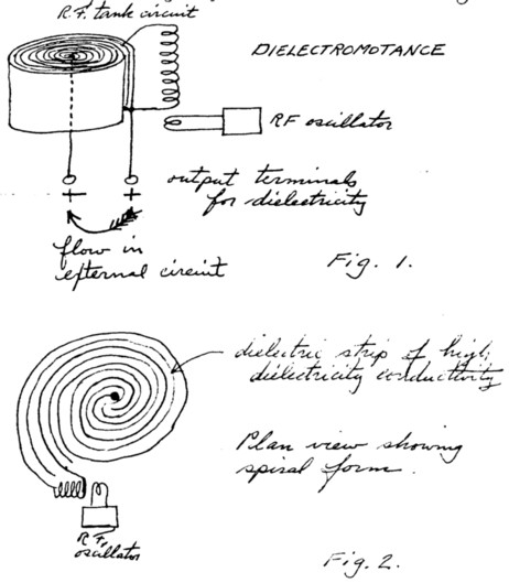
70. Dielectromotance (The Generation of Dielectricity)
71. The Flow of Dielectricity
72. Generation of Dielectricity by the Use of Alternating Current.
73. The Coiled Strip Capacitor as a Generator of Dielectricity.
74. High Flux, Closed Circuit Transducer for Dielectricty
75. Motion of Dielectric Media Produced by Dielectric Flux. Dielectric Wind.
76. A Method of Ship Propulsion using Dielectric Flux.
Page 1
Notes & Ideas
This is to be the first of a series of record books of notes and ideas, of greater or lesser importance, just as they occur to me. The pages are numbered and the subject reference will be given in an index. Where it appears of importance at the moment, the entries will be witnessed.
All of my life, it seems, I have jotted down notes on paper napkins and the like, which have ultimately been lost or destroyed. In many cases, these original notes and the dates of conception have turned out to be important and the loss of the record has been a serious handicap.
In the main, the ideas recorded herein and the hypotheses developed from these ideas will relate to the subject of gravitation and the relationships between gravitation and electrodynamics. They may present from time to time certain seemingly practical applications which may be patentable. All entries therefore are dated.
Thomas Townsend Brown
Leesburg, VA; October 1, 1955
Page 2 [blank]
Page 3
1. A Review of the Situation regarding Gravitational Isotopes
Leesburg VA, Oct. 7, 1955
(a) An announcement has been made both in the newspapers and on the radio (within the last few days) that the contract for the launching gear of the proposed space satellite has been awarded the Glenn S. Martin Co and the contract for the rocket motor to General Electric.
This brings to mind the statement of M. K. Jessup in "The Case for the UFO" --- "If the money, thought, time and energy now being poured uselessly into the development of rocket propulsion were invested in a basic study of gravitation, it is altogether likely that we could have effective and economical space travel, at a small fraction of the ultimate cost which we are now incurring, within one decade".
As to a study of gravitation, there are two phases --- (a) the dynamic and (b) the static. In dynamic considerations, electrical energy causes a local distortion in the gravitational field which results in the generation of a ponderomotive force and motion results. In the static considerations, an electric situation exists which causes matter to be lighter (or heavier) than it normally should be.
Page 4
In nature, matter has gravitational susceptibility, that is --- it is acted upon and responds to a gravitational field. This is expressed as gravitational mass, and bears no direct relationship to the inertial mass or reluctance to acceleration. The measure of gravitational mass is specific gravity.
A study of the specific gravity of the elements reveals that, in many instances, a wide range of values are observed for the same element. Even where the chemical purity of the element is uniform a change or range of specific gravity values appears commonplace.
It is my hypothesis that all elements are composed of lighter and heavier isotopes (values of specific gravity) which differ from the mean value of the composition as a whole. Where the lighter fractions predominate, the mean value of specific gravity is less than normal. It may be said to have a predominance of negative gravitational isotopes. Where the mean values are greater than normal, the composition may be said to have a predominance of positive gravitational isotopes. No element appears to be completely "normal" or free from this effect.
For any given element, there probably exists (and this remains to be shown) a reciprocal relationship between the gravitational mass and the inertial mass.
Page 5
Heavier gravitational isotopes of the element possess less inertial mass --- and vice versa. The product of the two forms of mass probably equal a constant.
mg mi = E.
The energy relationships probably are unstable, the tendency being to reach an equilibrium condition of equality.
mg = mi
The spontaneous evolution of heat as observed by Brush and Harrington appears to be associated with light gravitational isotopes. This means excessive inertial mass, the energy of which is radiated and lost, and this in turn is the cause of decay of the anomalous gravitational effect.
For example, the rare earth group of elements appears to have strong negative anomalies --- that is, they are lighter than they should be. That they should also exhibit relatively high evolution of heat (spontaneously) follows. (This heating effect by rare earth elements remains to be discovered). Assuming that such is the case, the heating effect is present only where equilibrium has not been reached, and the temperature differential is quantitatively related to the abnormal lightness.
Page 6
Since energy (thermal) is released until equilibrium between Mg and Mi is realized, it is obvious that the effect is subject to the usual rate of decay, reaching zero asymptotically.
In the case of positive isotopes --- an absorption of that would be expected. Such absorption would cause the sample to be colder than its environment.
If the effect noted above is not actually present (and there is as yet no evidence of heat absorption), it is possible that positive isotopes as such do not exist and that the present indicated mean specific gravity is actually negative and that the true "normal" or base is at least as high as the heaviest value indicated.
Methods of beneficiation are the subject of current patent applications. Methods involve successive steps of settling and centrifuging. The separation is of the isotopes in the mixture, (a) the lighter weight and more massive fraction and (b) the heavier and less massive fraction respectively.
No information has come to light regarding the modus operand of the creation of the light gravitational isotopes in the first place. It has been assumed, as in the case of mass isotopes that they have been present since the creation of the physical world.
Page 7
2. Nascent Gravitational Isotopes
Leesburg VA, Oct. 7, 1955.
The creation of light gravitational isotopes requires energy. Thermal energy is evolved during the decay of these isotopes, but it is probable that a greater source of energy than that available from heat is necessary for the creation of these lighter fractions. An exception may be taken, of course, to the high thermal energies present for example in the sun or during nuclear reactions.
Atomic piles provide energy through the fissioning of nuclei of the radioactive group to form nuclei of the rare earth group. These nascent isotopes may turn out to be a rich source --- produced in the same fashion as the rare earth elements were produced in the original creation (a primordial explosion).
One may speculate on other ways of creating gravitational isotopes, such as ---
(a) In targets receiving positive charges.
1. Hydrogen nuclei --- from cyclotrons or accelerators.
2. Hydrogen ions --- in electrolytic solutions.
3. Complex positive ions --- separation in semi-permeable membranes.
4. [ illegible, blurred photocopy ]
5. Cosmic ray showers.Page 8
It is to be recorded here that C.F. Brush once performed some experiments producing what he termed super-light hydrogen. It is said that this was done by some sort of preferred selection of ions in or during the electrolysis of water.
Page 9
3. Increase in Weight and Density of Certain Rocks
Leesburg, VA, October 7, 1955.
There appears to be evidence, however tenuous and perhaps controversial, that a civilization existed on the earth 70,000 to 200,000 years ago. It may be said that this civilization had simple and effective ways of moving stone --- based on today’s standards.
In the high Andes of Peru --- the Sachahuaman Fortress --- stones weighing 200 tons each were fitted together so closely that a knife blade cannot be inserted between them.
Enormous stones --- 14’ x 17’ x 70’, weighing upwards to 1200 tons, were moved and placed in position in various parts of the world. Baalbek, Easter Island, as well as in Peru. (See "Case for the UFO" by Jessup). It has been suggested that some form of levitation employed by the ancients made possible the moving of these enormous stones.
I submit that the weight of these stones may have changed since they were quarried, that the change may have been rapid at first and then slowed down as the years passed.
To develop this hypothesis, the following is suggested:
Page 10
At some time between 70,000 and 200,000 years ago, a worldwide change occurred which created or recreated light gravitational isotopes. This could have been a sudden increase in the intensity of cosmic radiation or it could have been a close approach or contact with a comet.
The result nevertheless was a rapid and effective increase in the content of light gravitational isotopes in certain susceptible materials. This increase presumably was limited to certain clays and rocks. The resulting loss of weight caused tectonic forces and started mountain building processes.
The continent of Atlantis may have risen from the ocean during this period. During the height of this gravitational revolution, many materials were phenomenally light and could be transported with ease. Certain substances may have had negative gravitational mass and escaped from the earth. Structures to fly in the air may have been constructed from common materials by beneficiating from entrapping or loading materials.
Men turned with ease toward the quarrying of huge masses of stone simply because they were able to lift and move them. It is my hypothesis that the largest stones cold be carried by a relatively few men. They literally floated through the air, like huge logs floating on water. Their inertial mass, however, must have been enormous. When motionless they must have required great force to start them moving and, when in motion, they must have required equally great effort to stop them!
Page 11
This period of "lightness" must have lasted many centuries, because during that time a flourishing, highly developed human society evolved.
Decay of the light gravitational isotopes began when the factor causing their synthesis ceased to be operative. This decay, similar to radioactive decay, was very rapid at the start, diminishing in rate as the centuries passed.
It is presumed that unless synthesis is now operating or has been more or less regularly operating during the intervening time, decay of this original effect is still proceeding. The result then would be a continuing increase in the weight of these rocks.
During the first few centuries of weight "increase", great tectonic forces similar but opposite to those which originally created "Atlantis", now served to destroy it. Great loading due to the increase in weight of these specific rocks, together with isostatic flow, would have caused the sinking of the mythical continent.
Page 12
In brief, therefore, the disappearance of Atlantis may be related to and concurrent with the termination of quarrying operations of the huge stones. The same increase of weight, caused by the decay of light isotopes, caused by the decay of light isotopes, is the reason, so it seems.
As the weight of the monoliths, such as the Easter Island images, increased, their supporting foundations gave way and caused them to fall. Most of these images have fallen backward.
It is proposed that samples of these monoliths (and others) be accurately weighed each year for several years, to determine if weight is still increasing. If so, and if rate has been undisturbed, curve may be extrapolated to indicate approximate date of vertical weightlessness (See above curve).
Typical half-life curve --- similar to decay of radioactive materials.
Page 13
4. Effects of Electrical Potential upon Gravitational Isotopes --- Controlled Lifting.
Leesburg, VA, October 7, 1955.
Two possibilities are foreseen:
(1) A static condition in which sustained electrical potential causes the effect, or
(2) A dynamic condition in which rate of change of potential causes the effect.Increase of negativity causes exogravitic field, increase of grav. mass (weight). Decrease of inertial mass and gravitational attraction.
Increase of positivity causes endogravitic field, Decrease of grav. mass (weight). Increase of inertial mass, and gravitational attraction
Tests: No. 1
A shielded analytical precision balance charged + or – , 50KV or more.
Weight (brass) on one pan
Sample of rock on other pan
Page 14
In the foregoing test, advantage is made of the differential effect between brass and the sample susceptible to grav. change.
Test No. 2 --- Sustained effects of sudden increase of + potential source 100 KV or more.
Sample insulated from ground.
Test No. 3 --- Same as above, but sample arranged to be struck by lightning!
In this connection, it is interesting to speculate upon the reasons for the levitation or lofting of certain terrestrial materials, such as pebbles, sand, etc., which subsequently fell back to earth.
Could it be that certain materials in the "target regions struck by lightning (from positively charged clouds) acquire lofting properties temporarily? Certainly it would escape notice.
Subsequently, as the lofting properties decay, the material will fall back to earth. One of the steps toward testing such a hypothesis would be to measure over a period of successive weeks the weight of a stone or pebble known to have recently fallen. Evidence of increase in weigh would be sought.
Page 15
5. Shift of Capacitance Mid-Point
Leesburg VA, October 10, 1955
This is a review and restatement of principles underlying the differential electrometer. The basic tests which are proposed are for the purpose of clarifying the operation of the long wave electrogravitic receiver, and to reduce its functions to simplest possible terms.
Audio transformer coupling to amplifier.
Potentiometer automatically seeking null position, with chart recorder.Page 16
6. Nascent Gravitational Isotopes --- Sec. 2 --- Excitation by Photons.
Leesburg VA, Dec. 25, 1955
An exact definition of a gravitational isotope, particularly one which sets forth physical forms, is urgently needed. It is almost impossible to make progress in any direction until this is done.
In searching various possibilities, the following interesting facts present themselves:
(1) In transistor theory, conductivity s attributed to the migration of "holes", as well as to electrons. The holes appear to possess (or at least exhibit the equivalence of unit positive charges, equal to the unit negative charges carried by electrons. As a matter of mathematical convenience, the holes may be treated as having the same mass as an electron.
(2) The definition of a hole is as elusive as that of a negative gravitational isotope. It is interesting to speculate for the time being on the possibility that there may be a relationship.
To begin with, they are holes in what? Apparently, valence positions in the crystal lattice where valence electrons are missing. But the mechanisms by which a vacancy can be passed on progressively, with the physical property of a mass in motion, is not clear.
Page 17
The revisions in the theory of conductivity, which have resulted of necessity from the study of semi-conductors, have provided evidence of "positive carriers" hitherto unknown or unrecognized.
It is significant that these positive carriers are influenced by electric and/or magnetic fields in a way which is equivalent in every respect to the behavior of positive charges. They are indistinguishable, therefore, from charges.
That they may exist in paired, dipole or neutralized relation with charges of opposite sign necessarily follows.
Just as in other examples of pair creation, a photon may supply the energy. It is not clear, for example, whether the photon actually "creates" the positive-negative pair( with a mass of 2m), representing the equivalent mass energy value of the photon, or whether the total mass (2m) remains the same, with the photon merely supplying the energy to dissociate the pair.
Furthermore, if a valence hole is filled by an electron of the same but opposite charge, both are annihilated, and an extra electron is necessary to produce any net effect.
The energy of annihilation is radiated as a photon.
Page 18
If valence holes are representative of a class of positive charges found occasionally in the electronic shells of atoms, one may speculate upon similar charges in the nucleus. In most cases, such charges would be neutralized by electrons, and not enter into the electric balance of the atom.
Now, therefore, if one takes the bold step of postulating that holes (either as found in crystal lattice, complex electronic shells or nuclei) are holes in the negative effluvium, what is their gravitational mass (weight)? Let us postulate the existence of an entity which is merely a rarefaction of the negative effluvium, as contrasted with a local compression of effluvium which may be an electron.
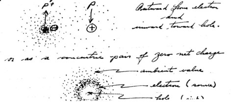
If then, gravitational potential is synchronous with the potential of the negative effluvium, gravitational gradients exist as follows:
Outward from electron and inward toward hole.
Or as a concentric pair of zero net chargePage 19
In other terms, the ether is the negative effluvium, the "elastic" compression of which represents potential energy. In the vicinity of large masses, the ether is less compressed, the potential energy of space is lower, but the potential energy of the mass is considerable (as represented by E + mc2), so that the total potential energy resident in the region is roughly constant everywhere.
In "free" intergalactic space --- let us say, in a mass free region (midway between the galaxies), negativity, and the compression of the ether is maximum. Space potential (gravitationally) is maximum. The potential difference exiting within an electron would be minimum. Electrons, as such, would be virtually indistinguishable from the ambient. "Holes", perhaps also positrons) would have maximum potential difference to their "interiors".
Page 20
At first impression, and this may be ultimately borne out, the electrons would possess weight (gravitational mass in the positive sense) whereas the "holes" may be lofting (negative gravitational mass). Both would possess inertial mass. A pair would be gravitationally and electrically neutral but would possess 2m initially.
When struck by a photon, a latent pair would be split, the energy of the binding supplied by the photon, with any excess providing recoil momentum to the pieces or parts so split.
Upon recombination, energy would be radiated as photons.
In summary, certain photo-emissive substances (perhaps complex silicates, lavas, and many other materials found in nature), when irradiated, may be found to lose weight. These materials would acquire a positive charge if insulated, but usually, in the process of weighing, the charge is lost. Similarly, the inertial mass (or the inertia with respect to the weight) will increase.
Upon standing, where recombination is permitted, heat (photons) is slowly evolved, causing the specimen to be continually warmer than its environment.
Page 21
7. Fatigue on Metals and the Creation of Light Gravitational Isotopes
Leesburg, VA, Jan. 7, 1956
In the Brush experiment relating to heat-treated metals, certain case-hardened steels indicated an actual loss of weight following the heat treatment. In measurements of the specific gravity (or density) of various metal wires (platinum, tungsten, etc.), the values observed seem to vary in an unpredictable way with the amount of drawing or working which has preceded the measurement. In most cases, working decreases the specific gravity.
In the measurement of specific gravity, it is desirable always to use the specimen which is most representative of the physical state of the material tested. In the main, the specimen should be free of porosity. Compression usually reduces this porosity and increases density.
After a certain point, further compression, hammering and/or working does not increase the apparent density of the specimen but actually decreases. The result appears to be an actual decrease in the weight of the specimen due to the working.
Page 22
One may summarize, therefore, that if the effects of porosity are not considered, continued working of certain metals reduces their specific gravity.
One may speculate, as a further step, that there may be a concurrent reduction of tensile strength with specific gravity, ad further, that the entire problem of fatigue in metals may be related to this phenomenon.
In pursuance of such a hypothesis, the following ideas emerge:
(a) Because of continuing flexing, a strip of metal becomes heated presumably due to inter-molecular friction. If course, the question as to whether the molecules in the crystal lattice actually rub together in the mechanical sense gives one misgivings. It is more accurate probably to say that the coulomb damping in and between the electric shells of the component atoms, carried in part by the valence electrons, causes the release of these electrons and the creation of "holes". Or, similarly, from an energy standpoint, the available heat (as photons) causes "electron-hole" pair creation, with a possible increase in the electrical conductivity in the flexed specimen.
Page 23
Based on the assumption that flexing increases the population of holes, it is reasonable to look for a decrease in weight. If the holes represent loss of valence electrons (binding energy or cohesive force), it is reasonable to look for a gradual or progressive weakening of the metal or fatigue.
(c) In and specific region, saturation of holes is reached when fracture occurs, or vice versa. This is also the point at which specific gravity is minimum, i.e., the sample is gravitationally lightest.
(d) A critical experiment suggests itself: A thin specimen of susceptible metals (aluminum, tantalum, tungsten, platinum) is carefully weighed. It is then continually stressed (or simply bent back and forth) until it fractures, care being taken to lose no pieces. The broken parts (in toto) are then weighed and the loss of weight (if any) is noted immediately.
(e) Due to the decay of the holes by recombination with electrons, the weighing of the broken specimen (pieces) must be performed as quickly after fracture as possible.
Page 24
(f) If such an experiment gives positive results, the following possibilities are of great interest:
(1). The production of light gravitational isotopes by mechanical manipulation.
(2) Large scale changes in weight due to tectonic forces and movement in the crust of the Earth.
(3) Nascent gravitational isotopes in recent lava "coolings" that have moved until cool.
(4) Loss of weight of recently forged specimens, hammered, hot or cold rolled, especially after excessive mechanical working.
(5) Loss of weight of recently crushed rock, pulverized sand or clays.
(6) Extension of knowledge as to the cause of fatigue (crystallization) in mtals.
(7) Change in properties due to cold flow as distinguished from elasticity.
(8) Spontaneous generation of heat as gravitational isotopes decay through annihilation of electron-hole pairs and emission of photons.
(9) Decay of heating effect according to half-life curve.
(10) Warmth of recently crushed rock or sand and the decay of the warmth with time.
(11) Altering the rate of decay, i.e., speeding up decay by negativity (elec.), slowing up decay by positivity.
(12) Effects of elastic field rate-of-change.
Page 25
8. Creation of Gravitational Isotopes. Sec. I.
Leesburg, VA, Jan 7, 1956.
The Possibility of creating (or energizing materials lighter than normal has interesting implications. It simply means that certain normal materials (in the sense that the ratio of mg to mi = 1 ) may be energized or activated so hat the ratio is less than 1.
Energy is stored in electron-hole pair creation which is returned to the environment only upon annihilation of the pair. Photons are absorbed and photons are radiated.
The following possibilities are inherent in the idea:
(a) Irradiation of loess by light (visible), ultraviolet, x-rays and gamma rays, producing lofting particles which decay and return to Earth.
(b) Sparked loess (positive sparks. Irradiate both by UV light and electric discharge).
(c) Pulverizing (additional grinding. Mechanical irradiation. See Sec. 7).
(d) In or near atomic piles or sites of nuclear explosions.
Page 26
9. The Postulation of an Anti-Gravitational Particle. Definition and Characteristics.
Leesburg, VA. Jan, 9, 1956.
In the foregoing hypotheses, the existence of lighter (than normal) gravitational fractions is proposed. It is reasoned that certain presently unexplained behavior of matter (such as the Brush Effects and the anomalous densities of many elements and compounds) may be adequately accounted for if one postulates the existence in nature of lighter and/or heavier fractions in the gravitational sense.
Development of this view introduces the necessity to define "mass" and to distinguish two kinds of mass:---
(1) Gravitational Mass (mg) as being the quality of matter susceptible to or reacting upon the (any) gravitational field, and
(2) Inertial Mass ( mi ) as being the quality of matter susceptible to or reacting with acceleration or centrifuging force.
A tentative relationship would be:
me mi = , constant,
where e is an unknown exponent.
The constant represents the total potential energy E of the mass in the equation E = mc2.
Page 27
Therefore, for any given mass, since E = mge mi C2 ; therefore, mge || 1 / mi.
For any given mass, the alteration of weight must accompany an alteration of inertial mass in an inverse relationship.
In the first concept of gravitational isotopes, the accepted value for the density (gr/cc) of an element or compound represented merely a mean value, with both lighter and heavier fractions in varying proportions being present.
If, for example, the mean value is less than the theoretically normal value (see chart of gravity anomalies of the elements), it is reasoned that the element, or at least that particular sample of the element, contains gravitationally lighter components.
Let us consider the nature of these lighter components.
It would appear that inasmuch as all elements exhibits the presence of those components, the active agent is probably common to all and may take the form of a fundamental particle --- of anti-gravitational properties.
Page 28
Such a particle may be said to have negative gravitational permeability and exhibit negative g. In free state, it would accelerate "upward" or loft. Its potential energy would be greatest, for example, at the surface of the earth and it would diminish as the particle "falls away" from the earth --- converting this gravitational potential energy into kinetic energy.
It will be seen that this property is the converse of that of ordinary mater. In this sense, such a lofting particle may be described as "contra-terrene". While the gravitational mass of such a particle may be said to be negative (for the reason that it is repelled in a gravitational field), the inertial mass is positive.
Hence, as the particle accelerates in escaping, it acquires momentum. This positive mass is revealed during acceleration and in any centrifugal situation.
Now, as to the nature of the anti-gravitational particle, considerable uncertainty exists in my mind. I shall try to resolve some of this, but the final answers can be given only after definitive experiments have provided the answers.
Page 29
In the foregoing entries in this book wherein gravitational isotopes were mentioned, the concept seemed to revolve around the possibilities of holes in the effluvium wherein a kind of gravitational buoyancy existed.
The holes of a semi-conductor appear as possibilities in this respect. If so, the anti-gravitational particle must be associated with electrical positivity. This would be particularly true if the effluvium itself is negative --- as an indefinitely extended diffuse electron ocean, but with a potential gradient to provide the direction of force.
Such holes are observed as the absence of electrons and hence behave as positrons. They are, therefore, of the same general magnitude as electrons. Holes and electrons are created n pairs by the action of a photon of the proper energy. It would tentatively appear that a low energy photon (heat) causes a slight separation of hole and electron, as in a dipole creation, whereas a high energy photon causes a further separation to the point where binding is lost and the separated particles take up independent lives. Here the energy of the photon equals or exceeds the binding energy of the pair.
Page 30
On a much smaller scale, but perhaps equally significant, is the creation of the neutrino and the anti-neutrino. Energy is required to create such a pair and that energy is released upon recombination or annihilation of the pair.
For the moment, let us consider only the possibilities of the larger scale effect; that is, those effects which can be operative in the shells of atoms rather than in the nucleus. Holes and electrons (as pairs), electrically neutral, can certainly be trapped in shells. Complex structures, such as are obviously present, for example, in the rare earth atoms, may contain such dipole structures or concentric structures formed of electron-hole combinations. Photons (energy) could cause and maintain such dipole or concentric structures. Heat energy could therefore cause expansion by the effects of increasing the physical separation of these pairs and the resulting chasing action (primary Brownian movement) of such dipoles.
Chasing action of an electron-hole dipole.
Page 31
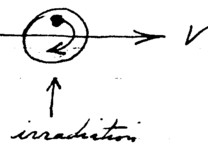
10. An Experiment to Show Lofting Effects of an Irradiated Dust.
Leesburg, VA, Jan 29, 1956.
A pulverized material, or a natural clay or loess, is placed on an electrode within a chamber capable of being evacuated. It is irradiated by a source of ultraviolet and/or visible radiation. The dust is observed through a telescope.
The pan maintaining the dust is charged electro-positively and the lighter particles are observed to "take off" and migrate under the action of the field toward the negative electrode.
However, the impressed electrostatic field is for purposes of control only. If true change of weight of a particle is observed, the electric field may be reduced, eliminated or reversed.
It is conceivable, however, that the lofting particles may bear electropositive charges naturally, hence will be more affected by the field and tend to separate from the unelectrified (normal) particles.
Page 32
11. Quantitative Weighing of Photo-Isotopes in a Precision Balance.
Leesburg, VA, Jan 29, 1956.
If it is found possible to create negative gravitational isotopes by irradiation, a measurement may be possible simply by weighing a shallow sample on a precision balance:
(1) under conditions of darkness
(2) " intense visible illumination.
(3) " " ultraviolet.
(4) " x-rays.12. The Photo-Isotope (Electroluminescence)
A metal can (a) is filled with loess (or equivalent). A fine ionizing wire is placed at the center, very highly positively charged.
Coronal glow irradiates the region immediately adjacent to the ionizing wire and the effects tend to spread to the inside walls of the cell, irradiating all of the material in the cell.
Active photoisotopic material in disc.
Page 33.
13. Increase of Inertial Mass in the Photo-Isotopic Cell, along with decrease in weight.
Leesburg, VA , Jan 27, 1956.
Proposed method of testing:
Arranged as a pendulum. Leads --- coaxial polyethylene cable. 50 KV +.
Observations of period.(1) Tests to be made with no charge.
(2) ""”"” (+) " applied.
(3) ""”"” (–) "".According to theory, the observed period with + charge applied should be longest, indicating:
(a) increase of inertial mass, or
(b) decrease of weight, or
(c) both.To separate these effects, an inertial device such as an anniversary clock or centrifugal (rotor) device may be used. (See Inertial Differential Electrogravitic Motor., Sec. 39).
Page 34
14. Centrifugal Inertial Effects on Electrically Modulated Photoisotopic Cells.
Leesburg VA, Jan. 29, 1956.
In the position as shown PC, is electropositive, hence gravitationally lighter but inertially more massive. The opposite is true of PC2 in the position shown.
A net force should therefore result as indicated, acting in the direction toward the positive electrode.
Rapid rotation should increase the force effective.
(This system, used as a motor, is described further in Sec. 39.)
Page 35
15. Beneficiation by Ion Separation
Leesburg VA, Feb 3, 1956
When irradiated, susceptible dust which bears a positive charge is attracted electrostatically to the negative electrode and falls to the right of center.
Heat and radiation is applied at positive electrode (which may be mechanically agitated). Sensitive dust which had become excited rises in electrostatic field to the negative electrode where it is neutralized and falls immediately.
Separation of suspended clay particles on the cathode.
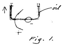
(1) Heavy conductivity (water) fluid
(2) Non-conductivity (oil) fluidPage 36
15. (Continued)
Separation by lofting property of dust, upon being excited.
16. Beneficiation by Differential Centrifugal Action
Leesburg, VA, Feb. 4, 1956.
As described in the project submitted to DuPont, one method of beneficiating light gravitational isotopes is the centrifugal action upon materials floating in heavy liquids. To go into detail, the following may be said:
To beneficiate kaolinite (aluminum silicate, density 2.5), the finely ground material is floated upon an aqueous solution of thallium malonate-thallium formate adjusted to approx. 3.0 density (sp. gr.).
In a gravitational field, the material floats on the surface of the liquid, but in a strong centrifugal "field", the aluminum silicate particles having a low g/i ratio will sink. If the settlings are fixed, either by freezing or compaction, they may be removed en masse after the centrifuge has stopped.
Page 37
17. Regarding a Measure of Centrifugal Force as Distinguished from Gravity.
Leesburg, VA, Feb. 5, 1956.
To rate a centrifuge as so many "g’s" is obviously incorrect and basically unsound, if one is to distinguish between the effects of acceleration and gravitation.
One "g" is defined as that force (due to gravity) which will impact an acceleration to a mass equivalent to that experienced at the surface of the earth, i.e., approx. 980 cm/sec2.
Centrifugal force, on the other hand, depends upon inertial mass only and is in no way equivalent to the force of gravitation.
Three factors affect the rate of fall, or, more accurately, the acceleration of a free-falling body, (1) The intensity of the gravitational field or gradient, (2) the susceptibility of the material being acted upon by that field, and (3) the inertial mass of that material.
Obviously, and contrary to the currently accepted postulate of Relativity, all materials in nature do no react to the same extent to gravitation and, further, the weight-inertial mass ratio is not the same with all materials.
Page 38
17. (Continued)
In a gravitational gradient or field fg, accel. = mg fg / mi where
mg = gravitational (susceptibility) mass,
mi = inertial massWhere mg = mi, the accel. is only dependent upon fg. A field fg which will cause the acceleration of 980 cm/sec2 under these circumstances is considered to be 1 "g".
Hence, we may refer to the ratio mg/mi, or simply the ratio g/i, as the "g-i" ratio. Under average conditions, when the ratio equals unity, there is said to be equivalence between weight and mass, as postulated by Einstein. However, when the "g-i" ratio is less than unity, the acceleration due to gravity is less and the acceleration in an inertial field is greater. When the ratio is greater than unity, the opposite appears to be true.
g / i = 1 (normal, mass-weight equivalence).
g / i > 1 (heavy gravitational isotopes prevail)
g / i < 1 (light gravitational isotopes prevail)
Page 39
Leesburg, VA, Feb 5, 1956.
The g-i ratio represents the gravity-inertial property of a material. It differs with different materials and with the same materials at different times or under different states of excitation.
When the g-i ratio is unity, there is an exact equivalence of weight and inertial mass. This may be described as average or mean condition.
Certain materials in nature apparently have less or greater inertial mass for a given weight (under similar circumstances) and such materials therefore have a g-i ratio differing from unity.
A g-i ratio is said to be high, normal or low depending upon whether it is above unity, at unity or below unity, respectively. Light gravitational isotopes present predominantly in a mass tends to lower the g-i ratio.
Examples:
Material A. Given a g-i ratio of 0.901, weight (gravitationally) 10 grams, Centrifuge rating 10,000 g’s; What is actual centrifugal equivalent?
10,000 / 0.901 = 11,090+ g’s equiv.
Page 40
19. Centrifugal Differential Hydrometry
Leesburg, VA, Feb 5, 1956.
Principles set forth in Sec. 16 and touched upon further in Sec. 18, are basically described as follows:
In gravity field of any value of g, scale set to zero hydrometer reading.
Then: When in centrifuge.
If material in hydrometer bulbs has a g-i ratio of 1, no other reading will be indicated whatever the speed of rotation.
If, however, material in bulb has a g-i ratio less than 1, hydrometer will sink lower in liquid as centrifugal force increases, the change in reading being proportional to the rate of rotation.
If, however, material in bulb has a g-i ratio less than 1, hydometer will sink lower in liquid, as centrifugal force increases, the change in reading being proportional to the rate of rotation (of the centrifuge).
If the material in the bulb has a g-i ratio greater than 1, the hydrometer bulb will rise in the liquid as the centrifugal force increases.
Page 41
The reading of a floating hydrometer during centrifuging may be accomplished by using an indicator coating on the stem of the hydrometer, the color or shading of which changes when in contact with the liquid. Such an arrangement will permit reading the position (maximum) after the centrifuge has stopped and the hydrometer returned to zero position.
The method is useful in determining the g-i ratio of any unknown material, simply by placing a known amount in the bulb of a standardized form of hydrometer, using a liquid the g-i ratio of which is 1, and centrifuging at a known rate. These materials may be in liquid as well as solid sate. The sensitivity increases in proportion to the speed of the centrifuge.
The advantages of the hydrometer method of determining the g-i ratio of a material is that it is self-balancing and independent of the compaction of material during centrifuging. The hydrometer bulbs, since they are made of glass (a silicate), must be carefully checked and isotopically balanced to prevent a contribution to the reading. Change in geometry due to compression of the bulb must also be taken into account, but this may be balanced out and disregarded when liquids or semi-fluids are tested.
Witnessed this 5th day of February 1956.
T. Townsend Brown
Witnessed Feb. 5, 1956 at Leesburg, VA,
Helen Brasafort
Joesphine B. BrownPage 42
20. Energy Changes and Excited States in the Creation and Determination of Gravitational Isotopes
Leesburg, VA, Feb 5, 1956.
Energy is required to create negative gravitational isotopes. This energy may be supplied in the form of protons (from infrared to gamma radiation) and conceivably also from high speed particles.
When applied to susceptible materials, this energy causes a temporary excited state, and this state accompanies a change in the g-i ratio to a lower value.
This excited state gradually deteriorates (probably according to a half-life curve) at different rates according to the material irradiated. The g-i ratio increases accordingly and approaches a value of 1 asymptotically. During this decay, energy is released, mainly in the form of heat, and to a small extant, possibly also as visible light.
This evolution of energy at a high rate may not necessarily indicate a low gi ratio but more probably a high rate of decay, i.e., a short half-life, and to some extent also, a recent irradiation. The evolution of light (if it does occur) would immediately follow cessation of irradiation --- and, as a matter of fact, may be present during irradiation, for decay would be proceeding at the same time as irradiation.
Page 43
The effect may be similar to photoexcitation of phosphors, the persistence of the radiation determined by the rate of decay of the excited state.
Immediately following removal of the exciting radiation, the luminescence and heating effect is greatest. The radiation diminishes as the excited state decays.
This suggests a beneficiated clay or other material which may be periodically excited and then (following irradiation) gives off heat slowly during the decay of the excited state. Thus such a material would serve as a heat reservoir with the energy stored as an electrogravitic excited state.
21. Certain Complex Silicates (natural clays, etc.) as Heat Reservoirs Following Irradiation by Sunlight.
Leesburg, VA, Feb. 11, 1956.
It is interesting speculation at this point to consider the possibility that certain desert sands and clays may thus become irradiated during the intense illumination of the day, and thus retain an ability to evolve heat through the night which exceeds the basic thermal capacity of the material.
Page 44
Concurrent with the irradiation, the material may become gravitationally lighter and, at the same time, inertially more massive.
If there is a fraction of the irradiated desert sand or clay which is sufficiently susceptible, to the extent that the g-i ratio decreases to zero or goes negative, the particles comprising that fraction may actually rise (loft) until nightfall stops the irradiation. At which time, the particles may start to return to earth --- falling perhaps like micro-meteorites.
Needless to say, a collection of this material --- beneficiated in this way by nature --- would be susceptible again to the same radiation. If the natural radiation could be intensified by a quartz lens or metallic parabolic mirror and focused upon a small sample of highly susceptible material, the probability is that the material would quickly loft. This would provide a simple and effective confirmation.
Along this line, it has always been a mystery to me why magnetite is found frequently on top of sand at the waterline on beaches both in rivers and at the ocean. If it were merely that the sand had washed away, leaving the magnetite on top, an explanation might be provided. But, in many cases, the sand has been recently deposited and it is not clear how the magnetite can be carried along with the sand in the initial process of beach formation unless the densities were of the same order and/or unless the magnetite fell as micrometeorites during or subsequent to the formation of the beach. The density of average beach sand is 2.5 gr/cm3 while that of normal magnetite is 5.5 gr/cm3, more than twice as heavy.
Page 45
Magnetite found in beach sands may therefore be a susceptible material. It should be investigated.
The same may be said for loess. The beach sand deposits of monazite at Jacksonville Beach, FL are also interesting in this connection.
22. Beneficiation of Light Gravitational Isotopes (by irradiation and selective lofting and falling) as it may occur on the Moon.
Leesburg, VA, Feb. 11, 1956.
Another purely speculative matter of interest at this point is the possibility of natural beneficiation occurring on the surface of the moon.
Due to the slow rate of rotation of the moon, the moon’s daylight is approx. 14 days in length and night is also 14 days in length.
Page 46.
During the long lunar day, temperatures rise well above 200-300° F in the surface materials. The radiation of the sun (due to the absence of atmosphere) is strong also in the ultraviolet. Conditions are sustained for 14 days which are especially favorable for the excitation of photoisotopes. Lofting of susceptible fractions of surface dust is indicated. This material rises to great height and part of it may escape into space. If a positive space charge is created by the first waves of lofting material, electrostatic repulsive forces may slow up further lofting.
Assuming then, a continuing lofting and falling process, the moon’s surface may become covered with a fine dust which engages every lunar day in a lofting-falling cycle.
The surface then becomes covered with an especially deep layer at the end of the lunar night. This may be a rich deposit of photoisotopic material actually beneficiated by Nature.
The question, of course, may be asked if similar conditions exist or may be made to exist, upon the earth. One may search expectantly, it would seem, at the edge of deserts --- especially on the downwind side.
Page 47
23. The value of "g" is not constant for all materials
Leesburg, VA, Feb. 10, 1956.
The acceleration due to gravity "g", normally about 980 cm/cm2, is the result of a force acting upon a mass.
a = f / m.If the f does no increase in proportion to m, a lower acceleration results: But this is inertia mass mi --- the reluctance to acceleration. The f is the force resulting from the action of the gravitational field upon the specific material. That action may be expressed as:
mg x fg. Hence,
a = mg / mi x fg.
mg / mi = g / i (ratio) , therefore
a = ( g-i ratio ) x fg
when (g-i ratio) is a characteristic of the material under (or at) a certain state of excitation where g-i ratio = 1, no excitation exists.
fg is a function of the inertial mass of the attracting body.
Page 48
24. Contact Excitation of Photoisotopes by Highly Energized Isotopes.
Leesburg, VA, Feb. 10, 1956.
A question presents itself as to the possibility that a highly energized body may transfer energy to a less energized body, either by conduction thru direct contact or by induction thru merely being in proximity.
Can, for example, a highly excited sand or clay energize rock? Can an excited gas (as in a positively charged fireball of nitrogen) excite the sand, gravel or other material by which it has been grounded and annihilated? Can the mere presence of contra-terrene material induce an effect of similar nature in a susceptible material?
Probably only experiment will reveal the answers. It is worth considering, however, for there are similar effects observable in other manifestations of energy --- such as heat, electrostatics, etc.
One immediately ponders the question as to energy excitation capacity, such as specific heat. Does a material of low specific (excitation) capacity transfer its energy to a material of higher excitation capacity, where there is only a slight difference in potential.
Page 49
This would raise the question that materials may differ in excitation energy) capacity. Hence, more energy would be required to excite certain atoms (or materials generally) than others. More energy would be released, and hence the rate of evolution would be greater, or the rate of decay would be greater --- or possibly both.
A measure of potential must then be foreseen. Raising the potential from one value to another, multiplied by the specific capacity, would consume energy, as
E = Pdif x capacity.
If then, a material of high capacity were to come into contact with a material of low capacity and would discharge thereinto, would the P reach a higher value in the second material? Based on analogous heat or electric situations, the answer would seem to be that the potential governs the flow, not the capacity.
Therefore, if a transfer of energy takes place, it is because a difference in potential exists. Energy will flow until the potential is equalized.
In energizing a material of high capacity, a flow similar to the electric charging of a storage battery takes place, with the potential rising as the charging continues.
Page 50
If the g-i ratio is a measure of excitation potential, then I must be in reciprocal relation. As an arbitrary zero, the g-i ratio of 1 can be taken. The excitation potential increases as the ratio decreases to zero. It continues to increase as the ratio goes negative. Let us divide the scale so that the distance from 1 to zero is 100 units. The distance from zero to –1 is then also 100 units, As: ---
Excitation Potential // g-i ratio
200 units // -1
100 " // 0
0 " // +1Therefore, in summary, a material will have mass-weight equivalence at zero potential, weightlessness and double mass (or some larger exponent) at 100 units and lofting at 1g and some still larger inertial mass at 200 units of excitation.
To excite a material, the energy (photon) equivalent of the excitation potential required must be supplied. In effect, this is electromagnetic excitation. This excitation must be continued for a length of time determined by the excitation capacity of the material.
Page 51
Just as in charging a storage battery, a longer time is required or a greater flow to charge a material of higher capacity.
Once charged, a material of higher capacity will continue in the excited state until discharged, and will last longer or discharge at a higher rate, or both.
If there is a difference in capacity of materials, it is logical to assume, at least to start with, that the capacity may be a direct function of the inertial mass at zero potential or grav. mass at any potential.
Hence, to irradiate a rare earth metal or tantalum would require more energy than aluminum or silicon, but the radiated energy during decay would likewise be greater. When once energized to a given potential, tantalum would give off more energy during decay to zero potential and would do so at a greater rate or for a longer time, or both.
Aluminum silicate could be excited to a given potential with less energy because its excitation capacity is less.
Now therefore, on the basis that the specific excitation is less than that of tantalum, it is clear that the decay radiation total will be different to the same extent.
Tantalum will absorb more energy and give off more energy in reaching the same excitation potential. The rate of charging will depend (1) upon the potential of the charging source and (2) upon the rate of charging (or flow).
Therefore, to return to the subject of this reaction, the rate of flow (conductivity) may depend upon the proximity and/or contact with the charging source.
If, for example, two pieces of tantalum having been differently excited (that is at presently different potentials) were brought into contact, energy would most certainly flow from one to the other. The flow would cease when their potentials balanced. This would constitute contact excitation of one by the other.
If highly excited aluminum silicate were placed in an envelope or container made of tantalum, contact would tend to cause the excitation of the tantalum, but the difference in the specific capacity would be so great as to virtually discharge the aluminum silicate without effectively draining the potential of the tantalum, unless, of course, the volume of aluminum silicate makes up for the difference in specific capacity.
On the other hand, highly excited tantalum could energize a large quantity of aluminum silicate without an appreciable drop in potential of the tantalum.
Page 53
One may speculate then that excitation in this respect is contagious from one element to the other, that there may be a variation from element to element, (1) in capacity, (2) in rates of spontaneous decay.
The more interesting elements, therefore, are those which have reasonably high capacity and very slow rates of decay.
Possible method for exciting rock through continuing contact excitation by irradiated sand.
Loess may be used in place of irradiated sand, and would be especially effective if beneficiated.
Beneficiating by contact excitation by dragging rock over desert sand.
Page 54
More modern method for doing same thing.
Tantalum lofting by excitation from corona photons.
The use of irradiated clay as a method to energize rock. In this respect, clay serves as an impedance matching device --- between the high potential of the exciting photons and the low potential of the rock or other solid material.
The ancients may have known that if they rubbed (Nile) mud, irradiated by the desert sun, on large rocks that the rocks lost weight until they could be easily carried.
Page 55
25. Preservation of the Rotation of the Earth by the Gravitational Differential of the Field of the Sun --- Due to Solar Irradiation of Photoisotopes.
Leesburg, VA, Feb. 15, 1956.
If the g-i ratio of the materials comprising the surface of the earth (including the atmosphere) is decreased by the action of sunlight, the following effect may account for sustaining the rotation:
The atmosphere, being free to slip, would move in the direction from W to E because of the differential field.
Correction: Perhaps it should not be called a differential field. What I intend to say is that it is a differential effect caused by two values of g large value on the west limb and small value on the east limb (of the Earth) in the gravitational field of the Sun.
Page 56
26. Factors which may cause the Rotation of the Earth.
Leesburg, VA, Feb. 18, 1956.
Neglecting all velocity components except the basic orbital velocity of the Earth, a situation with respect to the irradiation of the Earth by the Sun, and the inertial mass differential developed therefrom, may possibly account for a torque upon the Earth, as:--
Orbital motion of Earth.
Daylight side --- due to irradiation, mg/mi decreasing, mi increasingAssuming conservation of momentum, then since mi is increasing V1 must decrease. On the night side, since mi is decreasing V2 must increase. Hence, a torque is present tending to revolve Earth in the direction indicated.
This torque would be continuously applied and would increase the rate of rotation of the Earth without the present (low) limit were it not for the factors mentioned in Sec. 27.
Page 57.
27. Counter-Rotational Torque Tending to Limit the Rate of Rotation of the Earth.
Leesburg, VA, Feb. 18, 1956.
Considering now the rotation of the Earth as given, and neglecting all other velocity components, the following situation may exist:
On the daylight side, irradiation causes increase in mi, and a force tending to decrease V1 as shown as F1.
On the night side, decay causes decrease in mi and a force tending to increase V2, as shown as F2.
Since both of these forces are in the same direction, the result is a contribution to the orbital motion. It is this force which ma account for the basic orbital velocity (given in Sec. 26).
However, since the actual velocity of the Earth surface is the result of both orbital and axial rotation, the forces actually acting are as follows:
Page 58
V2 > V1
Irradiation causes increase in mi, hence F1.
Decay causes decrease in mi, hence F2.Since F1 and F2 contribute to the axial rotation, the result is similar to that indicated in Sec. 26, and we must look elsewhere for the counter-rotational torque.
It would appear at the moment that we must look elsewhere for this effect, and probably the most fruitful place to look would be in the solar-tidal friction produced upon and within the body of the Earth (including the oceans) as it revolves.
Such friction would increase quite rapidly as the rate of rotation increases, hence would soon reach an equilibrium revolution at a certain rate.
We can assume, I believe, that this equilibrium (in the case of the Earth) has been reached.
28. The Equilibrium Condition Between the Amount of Irradiation and the Orbital and Axial Motion of the Earth.
Leesburg, VA, Feb. 18, 1956.
In Sec. 26, orbital motion plus irradiation causes axial rotation.
In Sec. 27, axial rotation plus irradiation caused orbital motion.
Obviously, there is an interaction between all three factors, so that an equilibrium condition exists for all values of irradiation.
It is apparent that, in the foregoing, orbital motion per se is not required. What is required is that the relative position of the source of irradiation shall not change with respect to the body being irradiated. Hence to maintain a fixed relative position, orbital motion satisfies this requirement.
At any instant, therefore, orbital motion is equivalent to linear motion.
A summary of the situation, therefore, points to a possible interaction between linear motion, irradiation and particle rotation.
This inter-relationship may be observed in the laboratory.
Page 60
29. Conservation of Momentum and the Change of Velocity with Change in Inertial Mass
Leesburg, VA, Feb. 18, 1956
Basic considerations:
As mi increases, V must decrease, and vice versa.
If V is given, Rotation results is irradiation is maintained on one side of a photo-sensitive material.
If rotation is given, V results under same circumstances.
And the three factors are related in an equilibrium depending upon al three.
Torque such that mi increasing resists V, and falls behind.
Stable position.
Page 61
30. Detection of Absolute Motion by Means of Modulated Inertial Mass
Leesburg, VA, Feb. 18, 1956.
Postulate:
A force vector becomes apparent (1) in the direction of absolute motion whenever mi is decreased, and (2) away from the direction of motion whenever mi is increased.
The tendency is to conserve momentum.
Experiment:
When an alternating emf is employed (at a frequency synchronous with period of pendulum), the system will swing in an alignment with direction of absolute motion.
Witnessed this 18th of Feb 1956.
Helen Brasufort
Josephine B. BrownPage 62
31. Electrogravitic Radio Using Photoisotopic Cells.
Leesburg, VA, Feb 18, 1956
An improvement over the use of highly conducting metals as antennae (see pat. Appl. On subject) appears to present itself in the photoisotopic cell (See Sec. 12).
In Sec. 29 and 30, the effect of changing inertial mass was set forth. This is in accord with the law of conservation of momentum. This calls for a change in velocity according to the equation for kinetic energy E = ½ mV2.
Hence, for a given momentum
m || V2 or mi || V2
m being inertial mass as distinguished from gravitational mass (mg).
Any modulating inertial mass (mi) must exert a force during the time of change tending to increase or decrease its absolute velocity. As stated in Sec. 30, the direction of this force must be toward or away from the exact direction of its absolute motion (in space).
Hence, if an antenna (of an electro-gravitic radio transmitter) is electrically or photo-isotopically modulated, it will tend to vibrate mechanically in the alignment of its absolute motion.
Page 63
Conversely, one may look for the generation of an alternating potential if such a mass is vibrated in the alignment of its absolute motion (in space).
Since the velocity enters the equation with /as an experiment, it is possible that the voltage may turn out to be a function of the absolute velocity, but this will be discussed in a later chapter.
In any case, the use of photoisotope cells in electrogravitic radio transmitters is indicated. A fundamental circuit is as follows:
Transmitter >> gravitational radiation >> receiver
A transmitting antenna using a multiplicity of photoisotopic cells for modulating mi.
Page 64
32. A Rotating Electrogravitic Motor or Generator Using a "Velocity" Field.
Leesburg, VA, Feb 19, 1956
In the foregoing chapters, it was pointed out that the rapid modulation of inertial mass would cause mechanical forces resulting in vibration. The direction of the principal vibration would be parallel to the absolute motion of the mass.
Therefore, if a rotating system were synchronously excited (phased in with the rotation),
In this case, rotation would be impeded.
If turning clockwise, rotation would be assisted, and system would operate as a motor.
Case No. 2
Stable position. Same as Sec. 29, Fig. 5.
Page 65
Case No. 3
Given --- absolute V
" --- rotation as shown
" --- unmodulated mass
Then a potential would be generated.When a given inertial mass is at position 1, its absolute velocity is maximum. When the rate of velocity change is greatest (slowing), this corresponds to greatest positive excitation, etc., etc.
Any whirling dipole (uncharged initially) will acquire an alternating emf due to the "velocity" field, synchronized with the rotation. Or,
A revolving disc or sphere will do the same, as
The increased V is equivalent to a negative charge or high g-i ratio.
The decreased V is equivalent to a positive charge or low g-i ratio.
This generator effect may account for the day-night difference in potential in the surface of the Earth.
Page 66
33. A Rotating Electro-Gravitic Motor or Generator Using an "Inertial" Field.
Leesburg, VA, Feb 19, 1956.
The inertial field differs from the velocity field in this respect:
An inertial field is due to an acceleration or a change in velocity. It is measured as the rate of change of velocity.
The inertial field affects mi directly and produces a mechanical force proportional to mi, whereas the velocity field produces a mechanical force only when there is a change in mi and to an amount proportional to the rate of change of mi.
When excited as shown, (+) causes increase in mi, (-) causes decreases in mi, hence rotation results.
The inertial field can be created either by acceleration or centrifugal action. But in either case, force must be in direction as indicated to produce rotation as indicated.
When operated as a generator, polarity is opposite to that shown.
Page 67.
34. A Rotating Electrogravitic Motor or Generator Using a Gravitational Field
Leesburg, VA, Feb, 19, 1956.
The gravitational field has a similar but opposite effect from the inertial field as set forth in Sec. 33.
When excited as shown, (+) causes decreases in mg, (-) causes increase in mg, hence rotation is as indicated.
When used as a generator, polarity is opposite to that shown.
It will be seen that when wired in the same way, rotation is opposite to that of the inertial field motor.
Used in a detecting device, such a motor being identical to the inertial field motor, would rotate in clockwise direction of the inertial field predominated and in a counter-clockwise direction of the gravitational field predominates.
In this respect, this device would operate differentially.
When turned as a generator, the electric current generated would also act differentially, reading zero upon balance.
Page 68
35. Rotating Electrogravitic Motor or Generator Using a Velocity" Field.
Leesburg, VA, Feb. 19, 1956.
In order to describe it in a comparable way, the material set forth in Sec. 32 is redrafted as follows:
If mi in moving from A to B to C increases, absolute motion should be decreased, hence a force as indicated. In moving from C to D to A, mi decreases, hence V should tend to increase as also indicated.
The additional torque will cause the device to continue in operation after once started in the direction of the arrows.
When not excited and when used as a generator, the polarity is opposite to that shown. The reason is as follows:
When a mass is at point D, the V is greatest. When it moves to A, its rate of decrease of velocity is maximum. During this decrease of V, a positive charge appears, being a function of the rate. Similarly during the increase of V a negative charge appears, equal in magnitude to the rate at which the equivalent mass mi is decreasing.
Page 69
36. Use of Electrogravitic Generators as Measuring Instruments for g, i, and V ‘Fields".
Leesburg, VA; Feb 19, 1956.
When driven, the following rotors may develop an emf which depends upon the strength of gravity, inertial and (fixed velocity) "fields".
Rotation clockwise as shown, Polarity as indicated. Susceptible materials (unexcited).
Rotation same as above. Polarity is now opposite to that above.
To measure absolute velocity, an emf is developed as indicated.
This is a summary of the information set forth in Sec. 33, 34, and 35.
It is readily apparent that various combinations of the above may be used in balancing circuits to obtain special information as to relative "field" strengths.
Page 70
37. The Earth as the Rotor of an Electrogravitic Generator.
Leesburg, VA; Feb. 19, 1956.
It now appears that the polarities developed by both the g and i fields are in the same direction, but that the polarity developed by the velocity "field" opposes.
This situation is not clearly understood at the present writing. It will be reviewed at a later time.
38. Change of angular velocity with change in mi in order to conserve Angular Momentum.
Leesburg, VA; Feb 19, 1956.
Initial rotation given, when photoisotope cells on periphery of rotor are:
(1) negatively charged --- mi is decreased and rotor speeds up.
(2) positively charged --- mi is increased and rotor slows
The above is based on the conservation of angular momentum.Page 71
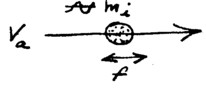
39. Inertial Differential Electrogravitic Motor
Leesburg, VA; Feb 19 1956.
In Sec. 13 and 14, attention was called to the possibility that the change in inertial mass mi, when modulated, could give rise to an unbalanced centrifugal force which could move the rotating system persistently in one direction.
This possibility is further explored:
When rotated at high speed and when using photosensitive material of very short persistence.
On the (+) side, g / i < 1 , or at least i (+) <> i (-), hence a force due to the unbalance of the opposing centrifugal forces is created.
This force (f) tends to move the system as a whole in the direction indicated.
It is clear that, at high rotational speeds, even a small inertial mass difference on the two sides could cause a substantial force upon the system as a whole. Even with crude materials the effect may be found to be easily observable.
Page 72.
40. The Loss of Weight of Quartz Capsules Containing a Photosensitive Isotope when Irradiated by UV Light
Leesburg, VA ; Feb 19, 1956.
A quick and yet convincing test (of Sec. 11) is possible by sealing a given amount of photoisotope in a capsule of fused quartz and weighing.
Weight should be taken of the capsule (1) in total darkness, (2) in normal light of the laboratory, (3) under UV light and (4) intense sunlight (without intervening glass).
The use of the quartz capsule prevents escape (evolution) of moisture during the irradiation, without filtering out the uv by absorption.
A standardized size of capsule may be adopted containing say 10 cc of material for comparison tests for loss of weight.
A laboratory precision balance, preferably "chainomatic" or equivalent is suggested due to the need for rapid determination of weight which is continually changing.
A curve showing loss of weight during excitation and gain of weight during decay will be required for a variety of materials.
Page 73
41. The Results of a Change of Inertial Mass Following Modulated Beneficiation (with Low Persistence)
Leesburg, VA; Feb. 26, 1956.
Part I. Change of Angular Velocity to Conserve Angular Momentum.
In Sec. 13, the possibility of a change in inertia mass of the photoisotope cell was considered. A laboratory experiment was described I which the period of a pendulum containing a photoisotope cell could be measured. The observations, however, would be non-specific as to the change in inertial mass per se, except when performed in an anniversary clock or centrifugal (rotor) device. It is the purpose of the present section to develop this idea.
Using several photoisotope cells (of low persistence) arranged on the periphery of a wheel-like support and connected so as to be charged in unison, as:
Given initial velocity --- when positively charged, mass mi increases, hence V decreases, or, When negatively charged, mass mi decreases, and V increases.
AC would cause periodic change in V.
Page 74
Another form of this experiment may be a disc which is energized (photoisotopically) from the center, as:
When unexcited and spinning at a known rate, then excited positively as shown, the inertial mass mi is increased, causing the rate of rotation to decrease.
When used as an anniversary clock, the period is lengthened by the application of a positive charge.
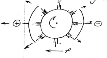
Part II. The Disc-Type Inertial Differential Electrogravitic Motor.
A development of the form of motor described in Sec. 39 is as follows:
In the "forward" part of the disc, sectors are being electropositively charged. Hence mi is increased.
The opposite is arranged for the trailing sectors, so as to produce a decreased mi. Rotation of these sectors having a mass (inertial) differential may cause the forward-acting thrust as indicated.
Page 75
42. The Impulse Effect in the Force Developed by a Simple Capacitor in Vacuum.
Leesburg, VA; April 7, 1956.
In the dynamic phase of the electrogravitic interaction, the force developed by a system of electric dipoles is believed to vary with the rate-of-change of the voltage between the dipoles.
This force, independent of the movement of ions or any mechanical reaction therefrom, operates in the direction of negative-to-positive as the voltage is increasing, and, presumably, in the opposite direction as the voltage is decreasing.
In vacuum (10-6 mm Hg or less), an interesting effect is observed.
Any simple vacuum capacitor will appear to flash as the voltage increases, and, concurrent with the vacuum spark, an impulse force is noted in the direction of the negative to positive. It is noted that the wave shape is as follows:
Page 76
According to theory, the impulse is associated with the recovery of potential and not with the rapid decrease brought on by the vacuum spark.
Two possibilities present themselves in explanation: (1) the decrease in potential is too rapid to produce an observable force mechanically, or (2) a balancing effect serving to prevent the force from being created may be present in the k-mu (ether) medium.
Therefore, since the downward voltage produces no force, the upward voltage is responsible for the observed force.
There is evidence to support the belief that a local balancing effect actually exists in the k-mu medium or field between or surrounding the electrodes, in that the effect is primarily observed when the voltage change is caused by a vacuum spark or flash between the electrodes and not when wholly due to a chopper in the external circuit.
The principal movement of the dipoles is therefore always associated with (and probably caused by) the vacuum spark or flash.
Page 77
43. The Nature of the Vacuum Spark, as related to the initiation of an electrogravitic impulse.
The vacuum spark is apparently not due to a flow of electrons, although a flow of electrons may accompany the discharge.
Initiation of the "flash", as it is called from observations in the dark, appear to be related to anode conditions such as shape (field intensity) and the metal comprising the anode. In a recently evacuated system, flashing starts at a comparatively low voltage, 30-40 KV. It becomes less frequent at this low range and then ceases altogether. A higher voltage is then required --- 50 to 60 KV, which causes a succession of flashes which, in turn, cease. At 80-90 KV, flashing is intense for a time, but finally ceases. At 130-140 KV, the flashing is quite intense and cease only after a considerable time. It is believed that a threshold may be reached between 150-200 KV where flashing will be sustained and continuous.
The electrogravitic forces developed by the rapid succession of impulses which accompany the flashing in the higher voltage ranges is indeed a first order effect, measurable in thousands of dynes, even with small scale equipment.
While the nature of the flash (or its cause) is not wholly understood, it is reasonable a this stage to suspect positive conduction, at least as the initiator. Emission from the anode, bombarding the cathode, may (and probably does) release electrons which contribute to the electrical conduction. Since the effect takes place in very high vacuum, it is unlikely that atmospheric ions or the like are involved. Occluded atoms or molecules are probably pulled from the anode material, and these, of course, may be oxygen, nitrogen, hydrogen, or any of the atmospheric gases. Metallic ions of the anode material may be involved, or perhaps even microscopic pieces of metal.
One of the spectacular features of the flash is the colored luminescence which appears on or immediately adjacent to the anode and/or the shifting areas of light and color across the face of the anode. The color is reddish --- like hot metal, although in reality the surface is not hot: Cadmium is especially active in this respect although other metals reveal the same red coloration. White star-like spots of considerable brilliance appear on the cathode.
Page 79
Leesburg, VA; April 7, 1956.
The above scale indicates a rough approximation based upon the hypothesis that normal g of 980 cm/sec2 represents an equal amount of inertia, so that the g/i ratio is unity. As the ratio decreases, the potential equivalent increases.
Energy is required to reduce weight, this energy increases exponentially as g is decreased linearly. The inertial mass (mi) increases exponentially to the same extent as the potential. Excitation is represented as potential and expressed in ghos. Decay of gravitational isotopes results from the evolution of this energy and the resulting decrease of potential.
Page 80
45. Possible Excitation of Gravitational Isotopes by Friction (Triboisotopes)
Leesburg, VA; Aug 26, 1956.
The possibility that loss of weight may be produced by friction should not be overlooked.
If a state of excitation, similar to that induced by uv light, can be induced by inter-molecular friction or by constant friction, the loss of weight may be readily detectable.
In Sec. 7, p. 21, the possibility that fatigue in metals, resulting from inter-molecular friction, may cause a reduction in weight was discussed at length. It was pointed out that coulomb damping may be accompanied by loss of weight in powdered susceptible materials.
A simple test may be as follows:
Quartz tube filled with sand, clay or other susceptible material. Weighed before and after shaking, the entire quartz tube with contents may show a loss of weight due to inter-particle friction.
Page 81
It may be found desirable to irradiate the tube and contents with strong sunlight or uv light while shaking is in progress. [N.B. – Ultrasonic resonance plus laser]
Beside the use of artificial light, sunlight may be intensified by quartz lenses or by a large parabolic reflector as follows;
Concentrated irradiation by sunlight plus violent shaking.
Using a large 60-inch Sperry Anti-aircraft searchlight mirror (without glass door), the radiation of the sun is focused upon the quartz tube filled with sand or clay or other susceptible material while being violently shaken by a motor device (not shown).
If effects are observed, quantitative measurements of the effects of the following may be undertake:
Shaking only --- various speeds, etc.
IR radiation only.
IR " with visible.
Sunlight (intensified).
UV only.
And all combinations of these.Page 82
46. Excitation of gravitational isotopes by friction irradiation and distribution and accumulation of the effects by conduction.
Leesburg, VA; Sept 9, 1956.
In Sec. 24, P. 48, it was proposed that rock ma be caused to lose weight by being dragged over desert sand which has been irradiated for some time by sunlight.
In Sec. 45, P. 80, it was proposed that friction alone may cause a loss of weight.
It is now proposed that a large effect may be caused by both.
Method which may have been used by the ancients to cause a loss of weight in very large and heavy rocks.
The effect would decay, causing the return of original weight, according to a half-life curve dependent upon the nature of the rock contents.
Page 83
47. Loss of Weight by Grinding or Pulverizing.
Leesburg, VA Sept 9, 1956
In the foregoing, it is suggested that fraction may be effective in bringing about a loss of weight, and that the loss of weight is temporary (after friction has ceased), so that the original weight will eventually return.
This may mean that a given weight of rock (of certain composition) may actually lose weight when pulverized and that the weight of the freshly pulverized material will be least and therefore increase according to the following type of curve.
During this decay period heat is evolved (thermoactivity).
Conversely, by observing accurately the increase in weight of certain pulverized materials (aluminates, silicates, etc.) the curve may be constructed and the approximate date of grinding may be determined.
Page 84
48. Spontaneous Evolution of Heat (Thermoactivity) of recently pulverized silicates or aluminates.
Leesburg VA; Sept 9, 1956.
Following the grinding of certain materials, a state of excitation is maintained for some time. This excitation gradually diminishes according to the same half-life curve which represents its return to normal weight. See Sec. 47., P. 83.
It is proposed that the foregoing be tested as follows:
Freshly ground material is placed in an ice calorimeter with a sensitive thermocouple in the center of the mass of material. Readings taken at frequent intervals for a period of at least 3 months.
It is believed that the energy represented in thermoactivity is that of an excited state in the electronic shells of the atoms or in the relations (valency electrons or holes) within certain molecular configurations. This energy is supplied initially by the mechanical action of friction (and/or irradiation) during the process of grinding. This energy is gradually dissipated as heat and the rate of evolution falls off with time.
Page 85
49. Discussion of Loss of Weight by Friction as present in Nature.
Leesburg, VA; Sept 9, 1956.
The mechanism of dust storms, where wind causes fine particles of sand or clay to rub over one another for a considerable distance may be responsible for a temporary loss of weight. The same effect may be present under water where the current causes sand to flow to and fro (as in wave actions) or straightway (as in rivers).
Due to the presence of sunlight irradiation, the phenomena of "rising" sand wind long noticed in the Sahara may be evidence of the above effect. Sand grains rubbing over other sand grains, by saltation, by the action of the wind, may cause the more susceptible grains to rise en masse and actually to loft to a considerable height, higher than they would normally go under the action of wind alone.
Aircraft flying at great altitudes over the Sahara often encounter these sand winds which are difficult to account for merely on the basis of wind-blown dust.
Page 86
50. The Possibilities of a New Type of Time-Space Data Preservation. A Method of Recording or "Memory".
Leesburg, VA; Jan 30, 1957.
All methods of recording music, sounds or time-series data, up to the present, have required the use of elements which are electrically or mechanically moving at a constant rate.
The phonograph is a classic example. Here, sounds are translated into mechanical vibrations which are recorded in a wax plate or equivalent which is moving at a constant rate. The magnetic tape or wire recorder is similar, except that magnetic variations are impresses upon the moving element.
In computing machines so-called electronic brains, memory devices are employed for the storage of data. These may be in the form of magnetic wire or tape records or, if greater speeds are required, mercury (transducer) memory tubes or television-like sustained images. Memory tubes require a recirculating sonic or ultrasonic path wherein the data is stored, and the cathode ray systems require continuous rescanning systems. Such recirculating or rescanning systems require a continuing source of energy in order to preserve the data indefinitely.
Page 87
It is suggested that a kind of memory may be inherent in the dielectric materials under certain conditions, so that, in effect, they may remember the manner of recharging. It appears possible that such memory may persist as long as the charge is retained.
The same characteristic may be present in certain magnetic materials and in a fashion which may be homologous.
Now therefore, it would appear to be desirable to explore these possibilities.
In general, it is suggested that two new forms of memory may be possible:
(1) Dielectric or capacitor memory.
(2) Magnetic or ferrite memory.A simple form of capacitor memory, for purposes of illustration is as follows:
Page 88.
By charging the capacitor at a variable rate as:
Domain progression. The electric orientation of dipoles proceeds at an irregular rate according to pattern prescribed by data feed. Upon reducing the electric field during subsequent discharge of capacitor, dipoles return to random (discharged) alignment progressively, according same or reversed pattern.
By introducing a leakage path, other and further paths may be produced.
Page 89
Capacitor Bridge for Exploratory Measurements
Procedure:
Charge A2 to –20KV steadily and without stopping.
Charge A to +20 KV irregularly and with frequent stops.
During charging, B-B is grounded by switch S, then switch is closed to meter M for duration of discharge.
Any irregularity in rate of discharge of A will show as a temporary imbalance of the bridge and a voltage indicated at M. (Brush recording galvanometer). Rapid transient imbalances will be most pronounced.
Page 90
51. Shift of Capacitance Mid-Point
Leesburg, VA; Feb. 1, 1957.
This is a continuation of discussion set forth in the Sec. 5, p. 15 of this record book. It relates to experiments conducted at Pearl Harbor Navy Yard in 1950-51. These preliminary experiments gave positive results, indicating a real shift of the mid-points with respect to each other with time.
Successive tests over an extended period of time and under conditions usually called equivalent revealed continuing (sometimes gradual and sometimes abrupt) circuit changes causing the indicated shift of (relative) mid-point.
It is thought that this phenomena relates to the action of the so-called sidereal radiation electrometer and that the variations or shift of the mid-point may have lunar, solar and sidereal cycles as recorded by the electrometer.
With automatic charging and discharging of the capacitors and means for continuous recording, it is believed that a pattern similar to the electrometer readings may be revealed.
The following circuit is suggested:
Page 91
Switch 1 closes for 30 sec each 3 minutes. Variac is so adjusted as to zero galvanometer 4 but at mid-point of 3, when 2 is closed. When 2 is opened, a voltage will be recorded at 5. If, in the preliminary adjustments this voltage is too high to be conveniently recorded, the recorder may be zeroed by adjusting the variac. This should then be followed by zeroing galvanometer 4 by changing position of slider 3. At this point, both the recorder and the galvanometer would be zeroed. Continuing operations will reveal a systematic shift of capacitor mid-point as shown by te record of voltage.
Page 92
52. Excitation by Impact of Highly-Charged Particles.
Nov 16, 1957
In Sec. 15, it was suggested that beneficiation might be achieved through ion separation. A development of this idea is as follows:
When the charge of a mass (according to electrogravitic theory) is made more negative, the mass becomes exogravitic during the interval of change. The exogravitic rate is a function of the rate of change of the electric charge.
Similarly, when the charge changes in he positive direction, the mass becomes endogravitic during the change.
Representation is as follows:
Hence, if a body is positively charged and loses that charge while in contact with a grounded (or negatively charged) mass, it is possible that the sudden and intense exogravitic radiation will be transmitted to and absorbed by the grounded mass.
Page 93
This suggests the use of an electrified sand blast.
***FIGURE
Since the positively charged sand is forcibly thrown against the susceptible material and loses its charge while in contact with it, the exogravitic radiation level is picked up by the material and diffuses through it in much of the same manner as heat. The susceptible material becomes progressively warmer (in terms of gravitational potential) until it potential balances the incoming potential (expressed in millighos). The electrogravitic capacity or retentiveness then determines the persistence of the effect.
During excitation, the higher millighos value should accompany the loss of weight. The interesting feature seems to be that the excited state acts like a heated state thermally and that it may represent another kind of "heat", engaging in conduction, radiation, and temperature equilibrium.
Conductivity of gravitic excitation through a material may differ markedly from one material to another. It is suggested that certain basalts, lavas and clays, perhaps also gravitic materials, silicas and some of the rare earth metals and tantalum may be found susceptible and useful in this connection.
High voltages (discharges in air) may produce the effect, especially where the voltages and momentary currents are very high as in a lightning bolt. A solid or gas which is near ground potential is suddenly struck by positive ions and rapidly moving dust particles. The result could be gravitic excitation of the solid or gas. It is conceivable that atmospheric nitrogen should be so excited --- producing the so-called ball-of-fire which has been observed to glow and to drift around like a toy balloon. See Sec. 4, Test No.2.
It is interesting to speculate also that the ""Brown Mountain Lights" may be caused by intense atmospheric electric gradients, with the ground negatively charged.
The light of the aurora may, in part at least, be due to the bombardment of crystal nitrogen by positive particles from the sun. An investigation of the luminosity of crystal nitrogen under positive rays may be in order.
Page 95
53. Dipole Motion Due to Excitation from Positive Rays.
Nov 16, 1957.
In Sec. 52, the idea that gravitic potential could be affected by the impact (stoppage) of positive rays was developed.
Such a material would lose weight in direct relation to the gravitic potential, that is, the mass would tend to become an antimass. Potential as expressed in millighos would increase until a balance is reached between the potential of the target and the potential of the individual positive rays upon contact with the target. The target, upon being excited, would be exogravitic, that is, it would have a higher gravitic potential than the ambient. The "g" gradient would be outward.
A dipole would look like:
with a g-force pushing the popsitive pole away.
Page 96
54. Static Counterbalance Produced by Positive Ray Excitation.
Nov 17, 1957.
Mass A suspended by a spring for observation of weight. Placed in vacuum chamber B, evacuated to 2.5 x 10⁻⁵ mm Hg, ionizing wire C serving as a source of canal rays which strike mass A at high velocity.
Upon stoppage of the canal rays, the high excitation potential is conducted to Mass A and distributes through it (in much the same effect as heating. Mass A gains gravitic potential to a value equaling the potential of the canal rays (during discharge).
Mass A then loses weight as it gains excitation potential, and rises within the vacuum chamber as the spring becomes less extended.
Page 97
55. Excitation by Annihilation of Positive Holes.
Nov. 18, 1957
In the foregoing sections, reference has been made to the possible excitation effects brought on by contact with charged masses or ions which initially possess a positive charge and are subsequently grounded, that is, grounded during contact with material susceptible to excitation.
Reference is to matter or ions. In the present section, it is suggested that so-called (valence) holes --- (See Sec. 9) might, upon annihilation, represent the source of a strong exogravitic radiation. Such radiation could be picked up by a susceptible electrode material which, in turn, would become excited --- gaining in potential Pg.
Ordinary transistor materials and methods may be employed, essential as follows:
Page 98
56. On the Meaning of "Field Shaping".
Dec. 27, 1957.
In nearly every experiment involving dielectrics and high voltage gradients, the shape of the field is a factor which must be considered.
A classical example is the force exhibited by a dielectric mass tending to draw it into a field (electric) if greater flux density. The force so developed is a function of the dielectric constant of the material. As:
Such a condition is present where electrodes are arranged as follows:
Page 99
Such a condition may be brought about by the shaping of a dielectric section as:
In these cases, the voltage gradients (both capacitance and resistance) are non-linear and look something like this:
Shape of field in dielectric sections.
The curve of potential is practically the same. Hence, in the small end, the flux density is greatest due to the requirements of capacitance distribution (upon charging), and then changes somewhat to meet the resistance distribution as steady-state current conditions take over.
The experiments to date have indicated that dielectric sections so shaped appear to move or possess a force (as a whole) as follows:
Motion of dielectric section away from end containing greatest electric flux density.
Page 100
This suggests that, if a dielectric fluid is present (perhaps ether), it is moved in the opposite direction thru the solid dielectric material. Perhaps a kind of "ether pump", as:
In the case of experiments on dynamic counterbary, the forces are similar probably.
Upper dome electrode (usually +; lower dome electrode (usually -)
Or:
In the case of units in multiple, where polarity is reversed in alternative units, field shaping may prevail over the usual neg-to-pos polarity arrangement, as dynamic counterbary sections in multiple connection:
Dynamic counterbary sections in multiple connection.
Page 101
In the foregoing, it would appear that ether, as a fluid dielectric with a K of unity, permeating the solid dielectric which is shaping the field, will move in the direction of the greater flux density as required by the classical experiment (p. 98).
The solid or physical elements of the system (which so shape the field) are moved in the opposite direction. These reactive forces and the motion resulting therefrom may be up or down (or in any direction) and conceivably can be used for propulsion.
In general, it appears that field shaping is of utmost importance in placing a region of high flux near an electrode or mass offering high reluctance to the flow of ether induced by the creation of the high flux.
The high flux creates a center of attraction for the ether which continues to flow so long as the flux exists. At the starting and stopping of the flow, inertial effects may conceivably be noted which are related to K and mu.
In the gyron in vacuum, the following arrangement is proposed:
If plate B is less permeable to ether than the grid or plate A, the flow being thru B into the high flux may cause the observed motion.
Page 102
57. Units in Multiple for Dynamic Counterbary.
Winston-Salem, NC,; Jan 1, 1958.
In the foregoing section, the use of field shaping was considered in multiple arrangement. The advantage of multiple connections is, of course, that lower voltages may be employed as the answer to larger sizes. Dynamic counterbary units then begin to look like this:
Regions of high flux density immediately about electrodes cause electrodes to be lifted. Airflow (plus ether flow?) may be in the opposite direction.
Shaped dielectric sections:
Page 103.
58. An Analysis of the Adamski Photograph in the Light of Recent Laboratory Findings.
Winston-Salem, NC; Jan 5, 1958.
This may be a bit of fantasy or it could be significant. It is a fact, nevertheless, that the behavior of laboratory models is quite similar to that alleged for the "Venusian" scout ship, and, what is even more provocative, the construction appears similar in many of the more important details. On examination of the photograph (reconstructed photographs and orthographic projections) is in order.
Note: Apex of cathode (shaped high flux) may be the focus of the parabolic anode (canopy), if indeed it proves to be parabolic. It could be te focus of a hyperbolic shape.
* Inside the Space Ships --- Adamski --- p. 128a(1).
Page 104
In the laboratory, the following shape gives a lifting force when charged as indicated:
In this diagram, the central (power storage) pylon is conceived as a gravitic dipole --- charged ends at a high potential (gravitic excitation) differential. Electric differential, it would appear, may accompany the gravitic differential.
Page 105
59. The Concept of the Gravitic Dipole as an Energy Storage Means.
Winston-Salem, NC; Jan. 5, 1958.
In the foregoing study of the Adamski Venusian scout ship and in the descriptive material pertaining to it found in the Adamski publication, the central pylon is referred to as place where energy is stored for the propulsion of the ship. It is stated that this central column must be recharged (by the mother ship), presumably as a storage battery is recharged.
The implication is that te central pylon is a kind of storage capacitor for electrostatic energy or perhaps even a pile of high capacity electret wafers serving the same purpose --- the stored energy being in the electric form (simple electrostatic nature).
To retain sufficient energy, if such a storage column is simply electrical, very high K materials and very high voltages would be required. Such high electrical fields would be difficult to contain without adequate insulation, especially thru the cabin compartment. Even with the very highest K materials available now (say 10,000 to 30,000 K), it is unbelievable that enough electrical energy would be stored to provide the propulsion and dynamic counterbary required.
It appears necessary therefore, to look further into the nature of the energy storage means. The following system appears worthy of study:
Page 106
If a column 16’ long by 2’ diameter, made of a suitably susceptible, highly retentive. High capacity material for gravitic excitation were used, the energy-storage requirements might easily be met. The column would constitute a gravitic dipole. It could be initially energized by a method such as described in Secs. 52-55 (electro-excitation), as:
Spraying continued until Pg of the lower end of the column increases to described value (2000 millighos or more). This is equivalent to a lofting moment of 2 g’s. At this Pg, the electrical potential may be formed to remain at some high value positive as a permanent state --- at least until the gravitic dipole is discharged or decays to zero. In this respect, the column is an electric (as well as gravitic) dipole when it is charged and the energy resides both as electric storage and gravitic excitation. Most of the energy in storage, however, would be represented as the gravitic excitation of the lower end. The electric field would merely accompany the gravitic difference of potential.
Page 107
60. Luminescence from highly-excited Materials; Gravito-Luminescence.
Winston-Salem, NC; Jan 5, 1958.
In connection with the gravitic excitation of materials, luminescence of the material itself as well as the surrounding materials (or gases) seems reasonable indeed. This is the type of thing one would expect if he were to attempt to account for the glow around soaucers hovering or in flight, as reported by so many observers.
Nothing, of course, of this nature has as yet been observed in the laboratory, and it is pure speculation as to its color and general behavior or even its existence. However, one may be able to foretell some of the properties.
In general, the radiation may be similar to tribo-luminescence, may actually be associated with tribo-luminescence, since friction also produces counterbary. Where gravitic excitation is carried to higher values, say 1 gho or above, considerable energy is in storage. Such energy undoubtedly would be found to have some have some radiant manifestation, since there would exist a steep gradient in the surrounding field. This gradient would dominate with the square of the distance. It would be greatest, therefore, immediately adjacent to the excited body, and especially around sharp points or edges where the field is steep. The effect may be similar, therefore, to electrical discharge (corona), may be present along with electrical corona and may, in some respects, be indistinguishable form it. Hence, saucers may glow from gravitic corona or electric corona or both.
Page 108.
In atmospheric air, electric corona is of purple color. A breakdown spark is blue. These spectral characteristics have been studied in great detail in the laboratory, along with the spectra of other gases (and solids) under electric bombardment or excitation.
Gravitic luminescence may come directly from the emitting surface or from the surrounding gas as gravitic corona. The spectra may be entirely different from electric corona, and more than likely it is quite different.
For example, on the basis of electric corona, it is difficult to account for the oft-reported flame-red color noted in saucers in flight. It is equally difficult to explain the shift in color from blue-white to flame-red, as the saucer maneuvers. These colors are not found in simple electric corona in air, and a change in voltage would not cause a change in color.
The flame-red color, therefore, is a stranger insofar as electric corona discharge is concerned. It is possible that this color is typical of gravitic corona
Page 109
In atmospheric air, at higher gravitic excitations or field strengths, the red color may become orange, orange-white, white or blue. This suggests the possibility of a continuous spectrum type of radiation similar to heat (thermo-luminescence).
This would mean, then, that the lower end of the dipole (column) shown on Page 106 would glow visibly when sufficiently excited by the spray of positive ions. Starting from a dull red, the luminescence might increase both in intensity and frequency (from red to blue) as the gravitic excitation continues. In this way, the nature (intensity and color) of the luminescence might be a convenient indicator of the degree of gravitic excitation. In other words, the color would reveal the amount of static counterbary as well as the gravitic excitation or total stored energy.
A gravitic dipole (as shown in p. 106) would appear luminous at the lower end but not a the upper end. At max. excitation, the color gradation would range from blue (at the lower end) thru white, orange-violet, orange, red and dull red to black (no radiation at the top).
The flame-red radiation would not necessarily be hot (thermally) in itself or represent a thermally hot surface. It would, however, represent a source of high energy or the storage of that energy (as gravitic potential) in matter.
Page 110.
61. The Use of the Toroid in Field Shaping
Winston-Salem, NC; Jan 12, 1958.
It is a basic requirement in shaping the electric field (p. 98) that the electric lines converge upon the cathode (as in Case No. 1). This normally requires a small cathode for high flux fields. Where a central pylon is used (as in p. 104 and 106), the high flux must be concentrated at the lower (cathode) end. A type of electrode is therefore suggested which accomplishes such field shaping. It is the toroid.
Such a curve of flux density fulfills the requirement described on p. 99. The center of the toroid could then be the focus of the parabola. The center hole would be just large enough to receive the dielectric pylon, with lower electrode at that center.
Page 111
62. Possible Magnetic Components in the Venusian Scout Ship --- Continued from Par. 3, Sec. 58
1-12-58
The main power coil, focused inside the cathode toroid, creates a field which saturates the lower (cathode) end of the pylon. The upper coil may be used to completely degauss the upper end o the pylon, or, working in conjunction with the lower coil, to distribute the field more evenly thru the pylon. Between these extremes, it could easily serve as as a central device for dynamic counterbary.
By adding the magnetic component, total counterbary may be greatly increased.
This effect would add to the force obtained electrically.
Page 112
63. Rotation of the Cathode-Toroid vs the Control Grid, as a Gyro-Stabilizer.
Winston-Salem, NC; Jan 12, 1958
It is apparent that some form of gyro-stabilization would assist the Venusian scout ship in maintaining course, and preventing wobble, both while hovering and while in flight. Such stabilization may be accomplished by rotating the cathode-toroid in one direction and the control grid in the opposite direction. The main body of the ship would then not be subject to rotational forces.
It is assumed that the 3-ball system for horizontal stability control (canting) would not rotate and would be used to set the basic direction of flight and counter any precession caused by the rotating system.
Rotation of the toroid (containing the power coil) and the control grid can be achieved by the electromagnetic coupling between the magnetic and electric fields. Forces applied and hence the angular moments would be equal and opposite between the two oppositely rotating members. Speed of rotation would be a function of the current and the magnetic field. If the current for the dynamic counterbary passes also through the toroidal coil. The rotation would be controlled entirely by the current, as created by the voltage on the control grid.
Page 113
64. Field Shaping in Positive Ray Excitation.
Winston-Salem, NC; Jan 13, 1958.
In Sec. 54, the use of positive rays for purposes of excitation in static counterbary was discussed. This represented what seemed to be a development of the ideas set forth in Sec. 52 wherein excitation was produced by the impact of highly-charged (material) particles.
The present section is concerned with the excitation possibilities of focused positive rays from a spherically-shaped anode of wire grid construction. Such a device would be especially useful in preliminary tests of susceptible materials in small quantities. Such tests would be conducted in vacuum and could be carried on with the material placed upon a small dish or pan atop a spring balance, capable of indicating the loss of weight as excitation proceeds. The arrangement would be as follows:
Sample would be in full view during excitation for studying color changes in gravito-luminescence.
Page 114
65. High Gravitic Potential Difference and the Phenomenon of Dielectricity.
Winston-Salem, NC; Jan. 13, 198.
There appears to be good reason to speculate at this time upon the effects attending high differences of gravitational (gravitic) potential If the potential gradient is exceedingly high (high flux density), the large energy difference would, it seems, attempt to energize itself. Thus, a kind of energy flow would be created from the high potential region o the low potential region. If the distance were small, this flow would be intense and undoubtedly would manifest itself in many curious ways.
Such a flow of energy we shall hereafter call "dielectricity".
Dielectricity would, therefore, be present more or less in every situation where there is a gravitational gradient. Its vector of flow would always be from the higher to the lower gravitational potential.
The situation is analogous to the flow of electricity (in the classical sense) from the positive to the negative potential or from the higher to the lower electrical potential.
Undoubtedly, such a flow of dielectricity would possess many interesting parallels to a flow of electricity. Both would represent a flow of energy from a higher to a lower potential.
Page 115
It is interesting to speculate upon the nature of the materials capable of conducting dielectricity and what materials might serve as insulators. One finds not only an analogy to electricity but also to heat, but the analogy with heat may be close in some respects (as in the conductivity or temperature distribution along a wire) and not in other respects as in phenomena arising from resistance to the flow. Resistance to the passage of current (flow) in electricity transforms the potential difference into heat. What happens when there is resistance to he flow of dielectricity, we can only guess.
Suppose, after we find a material capable of conducting dielectricity, we form it into a coil. What do we have generated in the place of a magnetic field? --- or is it a magnetic field?
What takes place when two plates of high gravitational potential are close together? Is there repulsion, as in static electricity?
And what if the plates have a high difference in gravitational (gravitic) potential? Is there attraction? And is there, in this case, a high flux density and a storage of energy in the space between the plates, acting like a capacitor? Is the energy stored in such a capacitor, and resident in the space between the plates, gravitational or something one step further.
Page 116
One may define a gravitational potential as a "pressure". The gradient between a high potential (high pressure) region in space and a low potential (low pressure) region is manifested as a gravity field (or just "g"). The vectors of this g-field are identical to the dielectric field vectors and both represent forces.
Hence, one would be led to believe that a flow of dielectricity, if resisted, would cause a force upon the body of the conductor --- much like the resistance to the flow of water against the walls of a tube through which it is flowing.
In the case of a gravitic (or dielectric) conductor, the factor creating resistance is gravitational reluctance (opposite to gravitational permeance or permeability). Such gravitational reluctance in the conductor of dielectricity would cause a force in the direction of the flow. In space, this force is simply gravity. Hence, it would appear that gravitational reluctance is created by (or equivalent to) gravitational mass Mg (as distinguished from inertial mass Mi.
The quality of conductivity of dielectricity is the opposite of gravitational reluctance, hence it is lack of Mg. Theoretically, a vacuum (complete absence of ponderable mater) is the best conductor.
Page 117
Conversely, ponderable matter of highest Mg represents a conductor of the greatest gravitational reluctance (resistance) and is therefore the best insulator of dielectricity.
This is virtually the opposite of the situation regarding the conductor of electricity --- hence the designation, "di-electricity".
Summarizing then:
Electricity --- conducted by metals, insulated by vacuum
Dielectricity --- conducted by vacuum, insulated by metals.Curiously, and this does indeed seem strange, the best insulator for the prevention of flow (loss in the central pylon (p. 106) is its weight (Mg). As a gravitic dipole with high potential at its lower end (cathode), the highest resistance would be provided by large values of Mg; this resistance causing an upward or lifting force in the transformation of the stored energy to motion and finally to heat resulting from resistance to that motion.
Such a pylon may be provided with lead (wafer) insulators dividing the pylon into sections of increasing gravitic potential in the direction of the lower or cathode end.
* any material of high Mg.
Page 118
66. The Push-Pull Effect of the Control Grid.
Winston-Salem, NC; Jan. 19, 1958.
In Sec. 56, the effects of high and low flux density were discussed, particularly as an explanation for the observed force or motion imparted to arcuate electrodes. The effect is determined by the direction of the flux gradient.
If, in the above figure, the anode is a grid of fine wires and the cathode is a ball, the force (as indicated) is especially pronounced. Reversal of polarity does not reverse the direction of the force. Due to increased current flow resulting from emission of neg ions and/or electrons from the grid, the reversed polarity does not appear to be efficient.
If the wind (specifically positive) is placed between two cathodes, as indicated in Figure 2,
Page 119
The force (as indicated) is virtually doubled.
It appears that the screen grid anode then attracts the ball cathode and repels the canopy cathode, so that the entire assembly moves in response to the force as shown (f). Thus we have named the push-pull effect.
This effect may be obtained in units such as Figure 3:
where the direction of the arculate surfaces create flux gradients to produce the force as indicated, or (Figure 4),
as a succession of units in parallel where the elements of each unit are concentrically arranged with the ball cathodes at the centers. The force of each (and every) unit is additive and directed as indicated.
Page 120
67. The Cylindrical Design of a Unit to Produce the Push-Pull Effect.
Winston-Salem, NC; Jan. 19, 1958
In the Vega Aircraft notebook, beginning Dec. 1, 1942 and ending sometime after May 2, 1944, and specifically described on Feb 4, 1943, a cylindrical system employing a shaped dielectric is described. Such a system is as follows (Figure 1):
Dielectric B has greater K and mass than dielectric sector A. Direction of force is as indicated.
This arrangement is the equivalent of that shown in the preceding Sec. 66 (Fig. 1), with the addition of 2 dielectroics, it being understood that Fig. 1 (p. 118) could represent the sectional view of a sphere or a cylinder. In either case, the requirement of field shaping and the resultant field gradient would be met. The force would be (as indicated) in the direction of flux gradient. In Fig. 1 (p. 120) the greater force is in the direction of the dielectric having the greater K or m (or both).
The use of the wire grid augments this effect so as to add the push-pull feature.
Page 121.
Such an arrangement then looks like (Figure 2):
Or, without the Km differential, simply as follows (Fig. 3):
May be filled with fluid or solid dielectric material, or separated in vacuum. Grid occupies about 120 degree sector.
In Fig 3, the location of the grid will determine the direction of the force, rather, the position of the dielectrics. Rotation of the grid 180 degrees will reverse the direction of he resulting force acting upon the unit as a whole.
High K, high m dielectric material, either as a fluid filling all of the inside of the can or as a solid encapsulating material will, it appears, increase the force. That material which is not in the active sector comprising approx 120 degrees where the grid is located will not add to the force, nor will it detract.
Page 122
The force for a given voltage should be a function of both K and m. In vacuum, with a K of unity and m = 0, the force should be minimum. It should increase with the use of a fluid dielectric such as oil, pyranol or carbon tetrachloride and even further with solid dielectrics which, at the same time, may serve to encapsulate the elements in the can.
In this connection, it may be pointed out that the solid dielectrics may take the form of tubes arranged as follows (Fig 4):
Drawing expanded radially for sake of illustration.
Force is always in the direction from the center (inner) cathode toward the center of the control grid. The control grid may be turned into other quadrants or the entire unit (encapsulated) may be turned in order to change direction of the force.
Page 123
68. Cylindrical Units in Parallel
Winston-Salem, NC; an 19, 1958.
It is readily apparent that the units described in Sec. 67 may be of commercial value in propulsion of ships, railroad or other land vehicles. In such practical application, units would be arranged in multiple.
Control of the direction of force would be accomplished merely by rotating the entire can if the elements are rigidly encapsulated ore by rotating the control grid with respect to the can if the elements are oil (or heavy fluid) insulated.
Units in parallel would look like:
In the above illustration, the cans are stationary and the grid is movable about the control axis.
Thrust is determined by the voltage applied (the current being determined by the resistance of the dielectric and the transformation requirements to kinetic energy).
Page 124
69. Self-Adjusting (Ionic) Oscillator and the Use of High Voltage RF in the Propulsion of Space Craft.
Winston-Salem, NC; Mar. 25, 1958.
Using the push-pull system of three electrodes (p. 118), it is possible that a resonant circuit can be established when the voltage between the outer two electrodes (and presumably also the lift) could be enormously increased. Such a system could use the three electrodes as a self-adjusting (ionic)oscillator.
In the above system, the DC exciter voltage need only be sufficient to establish oscillation in the resonant circuit. The high voltage for the principal lift would come from the delta (or equivalent) inductor.
Page 125.
70. Dielectromotance (The Generation of Dielectricity)
Winston-Salem, NC; march 31, 1958.
In Sec 65, I speculated upon the existence of high-gravitic potential differences and upon a flow resulting from such potential differences. In many respects such a flow would be analogous to the flow of electricity (or current). The flow arising from a difference in gravitic potential might be termed "dielectric current", in that it would presumably be conducted by dielectrics.
If one subscribed to the idea of an ether, such a flow could be viewed as a movement of the ether. The flow, of necessity, would be circulatory, creating one or more vortices.
It was pointed out that materials may offer varying amounts of resistance to such a flow, thus giving rise to a force of ponderomotive nature acting upon the interposed material. Such a force may conceivably be similar to, or perhaps indistinguishable from, the force of gravity.
The flow of dielectricity, whether or not it is responsible for gravity, results from a field in which there is a difference in potential --- not electric, but attending and usually created by an electric field.
Page 127
In Fig 2, the flow again is from the region of highest to lowest flux density, hence from the point electrode in the center to the toroidal electrode around it, and returning axially, as indicated.
Assuming the arcuate surface (in Fig 1) or the toroidal surface (in Fig 2) to have a gravitic (or dielectric) potential at or near the ambient, I is the center electrode which has the high gravitic potential --- at least, insofar as the generation of dielectricity is concerned.
The situation is similar to that of a battery and closed loop of an electric circuit, where the one side of the battery is grounded, as:
Another method of generating dielectricity (in greater volume) is the series or cascade arrangement, as follows:
Page 128
Generator of dielectricity as a 3-element dielectric ring with highly charged electrode (+) midwday between the center electrode (-) and the outer ring electrode (-_showing radial flow in the ring or disc from the center outward and returning through the environment (outer field) to the axis.
It is understood that while, in this drawing, the electric field is (-) to (+) to (-), the generator is equally operative in the (+) to (-) to (+) polarity. Reversal of polarity does not affect the direction of flow of the generated dielectricity.
Hence, it is readily understood that such a device will operate on AC, and at any frequency, always causing a flow of dielectricity from the center outward to the ring, thence returning through the exterior field to the axis.
The flow pattern is essentially two toroids with one side joined --- hence, interlocked and inseparable.
Sectional view of interlocked toroidal vortices.
Page 129
Walkertown, NC; April 7, 1958.
In the foregoing section, the generator of so-called dielectricity was discussed. It was pointed out that a flow could be created by a non-linear electric gradient and that the direction of that flow would be from the region of highest electric flux density to the region of lowest flux density.
In other words, a difference of potential is created which is not expressible in terms of electricity but which flows if a return circuit is provided. The flow does not necessarily follow a path o electrical conductivity (such as a wire) but arches through the environment in the manner of a magnetic field.
Preliminary experiments have indicated that the flow prefers glass or plastics as a path, hence, exhibits the characteristics of a flow capable of conduction. Since the materials revealing such conductivity are generally dielectrics, the entity comprising the flow has been named "dielectricity".
In summary, therefore, "dielectricity" may be defined as "an entity capable of flowing" which is "placed in motion" by a non-linear electric gradient and which flows from the region of high electric flux density (by the shortest route) to the region of lowest flux density, thence returning by an exterior circuit formed by materials which do not necessarily conduct electricity.
Page 130
If the behavior of such a flow is similar to that of magnetism or electricity, it is to be expected that an increase in conductivity of the circuit elements (or conversely, a decrease in resistance) will result in an increase in the flow itself. For example, in a magnetic circuit the more of the circuit which contains iron, the greater is the magnetic flux density. This is usually expressed as a decrease in the air gap. The factor introduced is the integrated mu for all sections of the magnetic circuit.
In the present instance, where we may be talking about a dielectric phenomenon and a flow of dielectricity, the integrated K may be the factor which is significant. On the other hand, if the characteristics of the flow of dielecticity or the results of a difference in potential of dielectricity are gravitational, then the significant factor may be mg or the gravitational mass of the circuit sections. If both are involved, as perhaps an electromagnetic phenomenon, then both K and Mg are important factors in the circuit. The final answer to this question cannot be given until precise tests of various materials can be completed.
Page 131
One characteristic of the flow of dieletricity appears to be its ability to create a force on the material through which it is slowing. It may be said that it was largely through the indications of its forceful effects that its presence was initially detected. In practically every experiment where a flow of dielectricity is established, an air flow results in the direction of the flux. In the beginning, the air flow was so pronounced that it was difficult to purify the results so as to eliminate what appeared to be the effects of an "electric wind".
It is to be noted that the classical concept of electric wind is perhaps inseparably confused and inter-related to the effects of a flow of dielectricity. Any electrified point, according to classical concepts, produces ions of the same sign as the point and hence are repelled by the point, producing a motion of the medium when their momentum is transferred to that medium. It is assumed that the reaction, resulting from the repulsion of the ions from the point, will drive the point in the opposite direction and that this reaction will be exactly equal and opposite to the forward momentum of the wind.
Page 132.
A simple experiment will reveal that this is not necessarily true:
Net force on system of two electrodes is as shown. Measured only on the two electrodes.
In the above experiment, only by considering the forces acting on the medium to the side of the alignment of electrodes (which are in a direction from right-to-left) will the net force (as indicated) be eliminated.
It is obvious that the classical concept of the electric wind does not explain a movement of the medium from right to left (in the above explanation).
On the other hand, the classical concept explains the left-to-right momentum but cannot explain the lack of balance which causes the net force as indicated.
In Sec 70. it was shown that a flow of dielectricity probably results from any situation in which there is a no-linear electric flux density.
Page 133.
In the illustration on the previous page, there is a strong non-linear gradient on the electric field between the sharp point and the large arcuate electrode. The greatest density exists around the end of the point and falls of to a minimum at the arcuate electrode.
Hence, according to the principles set forth in Sec. 70, a flow of dielectricity is created by such a configuration as follows:
Flow of dielectricity causes movement of dielectric fluid.
Such a diagram, however, neglects the flow of dielectricity which is conducted through the leads of the power supply, as:
Flow of dielectricity through electric source in same direction as classical electric current.
In general, however, where the wiring of the electrical supply is long and/or involved, a consideration of dielectric flow parallel with the electric flow is unnecessary. Even so, it may be completely and finally eliminated by the following system:
Page 134
Three-element System:
Where high impedance elements are placed in feed lines, flow of dielectricity assumes a shorter closed circuit path through the immediate environment.
Now, excluding the electrical feed lines, the path becomes simply a closed toroidal vortex, as:
If the above vortex is acting within a dielectric fluid (such as oil or air) the fluid assumes a toroidal vortex as the structure (geometry) of the electrodes permits. The resistance of the fluid to the flow of dielectricity results in a movement of the fluid. That part of the flow which impinges upon the electrodes tends to move the electrode system. Hence, the electrodes (in the illustration) tend to move upward while fluid, particularly near the periphery of the electrodes, tends to move downward.
Page 135
If such a system is placed in a metal (almost infinitely high K) enclosure, the following field distribution takes place:
The conductivity is so great that virtually no flow appears externally.
Due to the partial closing of the air gap by high conducting material, the flux density is greatly increased. This increase in flow of dielectricity will cause an increase in the lift of the electrode system within the enclosure. The downward flow through the walls of the enclosure will, however, be sufficient to virtually balance the lift if the electrode system is mechanically attached to the metal enclosure.
In other words, placing the electrode system within the can greatly increases the lift of the electrode system by itself. But, a force virtually of the same magnitude and opposite in sense is created within the walls of the can, by reason of the resistance to the flow offered by these surfaces or (perhaps more correctly) these volumes of upper high-K materials.
Page 136
No secondary flow patterns are established outside of the can due to the ability of the metal walls to conduct all of the flow of electricity.
The effect is similar to the ability of iron cores (of high magnetic permeability) to convey all the magnetic flux, allowing the establishment of no flux outside. This will, of course, be true up to the point of saturation, where a further increase in flux cannot be carried and leaks out into the surrounding space.
When saturation to the flow of dielectricity has been reached, the flux which leaks out causes secondary flows or "reversed" vortices, as:
3-Element dielectricity generator in thin Saran bag
Page 137
The friction of the moving air both inside and outside the container (upon the walls of the container) then causes the can to move downward, while the air farther away moves up.
In this way, an electrode system encased in an enclosure where the flux density is beyond saturation (as with a Saran sheet enclosure), the force acting upon the system appears to be reversed.
Increasing the thickness of the Saran or by using dielectrics of greater conductivity of dielectricity, this effect of reversal may be reduced or eliminated entirely.
Penetration of a saturated sheet of thin Saran.
Using Saran as an example of material which may be saturated when in thin sections, the following experiment is suggested:
Showing balance or possible null between primary and secondary flow.
Page 138
In the foregoing experiment, the electrode system is suspended for lift measurement within a Saran bag. Complete reversal of force, due to saturation, is observed, and the entire rig possesses a force downward.
If then, the rig is placed in a metal can, a complete reversal to lift may be observed for small diameter metal cans. The force downward will persist in larger diameter metal cans. A size of metal can, between these two extremes, may be found where no force exists. This null will represent the balance between the primary flow which penetrates the Saran bag and the secondary flow created by the saturated bag.
Another experiment which is suggested to test the saturation theory is the use of multiple layers of Saran, each layer contributing to the flux conductivity, whereby the addition of each layer reduces the reversed force a given amount, finally increasing the conductivity to the point below saturation (for that particular voltage) where the force is zero. At that voltage, the flux (being fully conducted) produces no force. At a slightly higher voltage, the flux being greater, is not fully conducted by the now saturated Saran sheets, and hence gives rise to a reversed force due to the secondary or exterior vortex.
Page 139
72. Generation of Dielectricity by the Use of Alternating Current.
Walkertown, NC; APR. 7, 1958.
In Sec 69, the use of high voltage RF for the generation of dielectricity was proposed. The circuitry included a self-regulating oscillator fed by a DC exciter.
It must be borne in mind that the generation of dielectricity is a kind of rectification process, producing unidirectional flow of dielectricity from either electrical polarity. Hence, AC at any frequency will generate dielectricity.
Where the dielectricity generator possesses a natural capacitance, the circuitry may include an inductance for operation as a tank circuit at any desired frequency.
Such a circuit is as follows:
Concentric type dielectricity generator using AC.
The flow connectors must (electrically) connect every other ring as indicated. The flow of dielectricity is outward from the center.
Page 140
73. The Coiled Strip Capacitor as a Generator of Dielectricity.
Walkertown, NC; April 8, 1958.
It is proposed that the spiral or coiled-strip capacitor may make a very convenient and cheaply constructed generator of high potential dielectricity.
Page 141
Using the spiral generator in the propulsion of a space craft, the following may be suggested:
The advantages are that the electrical circuits be limited to the spiral and the inductor. The dielectric circuits would include the A frame and the rubber (as the center of the spiral). Hence, there would be no electrically charged elements under the craft. The voltage used in the RF drive for the spiral capacitor would be relatively low.
No electric potential would exist between the high potential dielectricity terminals, nor in the external circuit. All luminous phenomena would arise from the high potentials of dielectricity present in the force field.
Page 142.
74. High Flux, Closed Circuit Transducer for Dielectricty
Walkertown, NC; April 29, 1958.
In the foregoing sections, the pattern of circulation of dielectricity was indicated in a number of instances. The flow invariably is from a region of high electric gradient to low electric gradient, such as:
(1) Outward from a highly charged point into the environment
(2) Outward from an inner electrode to an outer electrode. May be arcuate and may be concentric.
(3) From the small end toward the large end of a dielectric under electric strain --- may be wedge-shaped or cone or pyramid frustrums.
(4) From the high-gradient end to the low-gradient end where the non-linear electric gradient is established through external circuit resistance such as leakage.
Page 143.
(5) From the low density end (or low K or mu) toward the high density end (or high K or mu) where an electric field exists in a non-homogeneous dielectric.
In (3), the flow of dielectricity is created initially by the wedge-shaped or truncated cone shaped dielectric. Such a member is a "dielectromotance". The return circuit for the dielectric flux is through the medium immediately surrounding the member, as:
Where two members are related in series, the flux density is increased and the air gap (free path through the medium) is shortened, as:
Circulation pattern of dielectric flux between two dielectromotances in series.
In the above circuit, the (total) dielectromotance is doubled and the flux density greatly increased by reducing the air gap.
Page 144.
74. (Continued)
In the transducer, which is the subject o this section, the arrangement is as follows:
These forces may be of a high magnitude when high K material is used in the conical (armature and stator) sections. Rubber or plastic diaphragms may be used to hold the armature in position yet permit limited vertical (axial) movement. The device may be studied at high voltages either in vacuum or under oil.
Such a device is a transducer, between electrical and mechanical energy.
Page 145.
74. (Continued).
When electrical energy is supplied to either or both members, motion results.
If one or the other member is energized, and mechanical motion is supplied, an electric current in the second member will be generated. Such current will vary in accordance with the motion. Hence, the device will operate as a vibration pickup or microphone as well as an oscillating force generator or loudspeaker element.
Also, where all electrical conditions are rigorously constant, the force will vary according to the flux density. If such flux density within a closed system such as this varies with a linear, solar or sidereal diurnal pattern, such pattern will show upon a suitable force recorder operating for time-series observation.
As an actuating mechanism for such a recording device, the apparatus appears to have great promise.
Page 146.
75. Motion of Dielectric Media Produced by Dielectric Flux. Dielectric Wind.
Winston-Salem, NC; May 1, 1958.
In all of the experimental work to date, the results which have led to the concept of dielectricity and dielectric flux have carried one characteristic in common --- i.e, force or motion exerted upon dielectric solids or fluids.
In general, the source of the dielectricity or dielectromotance possesses a force in one direction whereas the balance of the circuit exhibits a force in the opposite direction, as:
If the return circuit is in air, oil or other dielectric fluid, the force results in movement of the fluid. In many cases where the electrodes are charged with respect to the medium, the flow may be mistaken for electric wind. It is usually quite difficult to separate these effects.
Any highly electrified point produces ions which are repelled from the point, giving rise to a motion in the medium known as electric wind.
In the same structure, the non-linear electric gradient outward from the point constitutes a dielectromotance and gives rise to a flow of the medium outward from the point ad in the direction of the decreasing flux density. Hence, the so-called electric wind may in fact be a total of the two effects. See p. 142 (1).
Page 147
Only by creating a dielectric potential difference where there is no electric potential difference, can the pure dielectric wind be separated from the electric wind. This is possible, it would appear, in the following structure:
In these circuits, two dielectromoances are connected in series, and the dielectric potential difference is doubled. The flow is in the closed circuit as indicated.
Page 148.
Another way for detecting the force acting upon dielectric media is the hydrostatic pressure developed by oil within an insulating tube.
(1) Increase in height of oil column due to pressure as indicated.
(2) Same as above but with three turns of tubing, increasing the pressure 3 times.
(3) Using a series of arcuate or conic field-shaping devices
(4) Motion of dielectric rod.
Page 149
If dielectric flux creates a potential difference which is additive with each turn, such as the hydrostatic pressure would be in Fig 2, then the following may produce interesting results:
If the flow if dielectricity is conceived to be from a higher to a lower potential, then the end of the conductor at point A will have the higher potential. The flow will be toward B in the external circuit.
If AC is used, frequency of the dielectricity is double the frequency of the supply electricity.
Page 150
Inductive force effects created by a coil carrying dielectricity.
Figure 1. Causing rotation of adjacent disc.
Figure 2. Causing rotation of core (axis)High potential dielectromotance with a large number of turns of dielectric conductor. Shown in Fig 7. p. 147.
Page 151
76. A Method of Ship Propulsion using Dielectric Flux.
Walkertown, NC; July 7, 1958.
If the dielectric return circuit passes thru the water surrounding a ship, it would seem entirely possible that the ship would be propelled.
Such a requirement would be satisfied by the following scheme:
Applied to a ship, the design might take the following shape:
Entire water body is the cathode envelope and is driven astern. Ship (dielectric) is driven forward.