rexresearch.com
rexresearch.com
Vapor Carburetor Patents
6 US Patents claiming greatly improved mpg by heat-vaporizing fuel :
USP 2218922 -- Vaporizer for Combustion EnginesSee also : Vapor Carburetor Patents ** WESTON : Air/Vapor Fuel System ** BUSHNELL : Vapor Fuel Engine ** Carburetors (Vapor ) ** GODWARD : Fuel Vaporizer ** JACKSON : Vaporous Gas Aspiration System ** LaFORCE : Vapor Fuel System ** MEIERBACHTOL : Fuel Atomizer ** OGLE : Fuel System ** PANTONE : GEET Fuel Plasma ** ROWLEY : Vapor Carburetor ** SHELTON : Vapor Fuel System **
USP 2982528 -- Vapor Fuel System
USP 3294381 -- Carburetor
USP 3653643 -- Carburetor
USP 2761660 -- Fuel saving attachment for an internal combustion engine
USP 4458653 / USP 4506647 -- Vapor fuel system for internal combustion engines
US2218922
VAPORIZER FOR COMBUSTION ENGINES
This invention relates to fuel vaporizing devices for combustion engines and more particularly is concerned with improvements in devices of the kind wherein provision. is made for utilizing the exhaust gases of the engines as a heating medium to aid in the vaporization of the fuel.
One object of the invention is to provide a device which will condition the fuel in such a manner that its potential energy may be fully utilized, thereby insuring better engine performance and a saving in fuel consumption and preventing the formation of carbon in the cylinders of the engine and the production of carbon monoxide and other objectionable gases.
A further object is to provide a device which is so designed that the fuel is delivered to the cylinders of the engine in a highly vaporized, dry and expanded state, this object contemplating a device which is available as a muffler and in which the vaporization and expansion of the liquid components are subjected at sub-atmospheric pressures and prior to their mixture with the air component.
A still further object is to provide a device which will condition the components of the fuel in such a manner that they may be uniformly and intimately mixed without the use of a carburetor.
A still further object is to provide a device which will enable the use of various inferior and inexpensive grades of fuel.
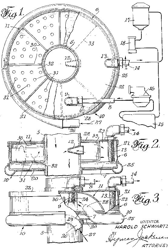
The invention is illustrated in the accompanying drawings, in which+ Figure 1 is a view in elevation of the device as applied to the engine of a motor vehicle;
Figure 2 is an enlarged view of the device, partially in elevation and partially in section;
Figure 3 is a section taken along line 3-3 of Figure 2;
Figure 4 is a section taken along line 4- 4 of Figure 3;
Figure 5 is a fragmentary line 5-5 of Figure 3; and
Figure 6 is a section taken of Figure 4.
The device, as illustrated, includes similar casings 8 and 9 which are secured together as a unit and which are formed to provide vaporizing chambers 10 and II, respectively, it being under- I stood that the number of casings may be varied.
Two series of ribs l2 are formed in each of the vaporizing chambers, the ribs of each series being spaced from one another to provide branch passages l3 and being spaced from the ribs of the adjacent series to provide main passages I4 with which the said branch passages communicate.
section taken along along line 6-6 The vaporizing chambers are closed by cover plates IS. The latter carry baffles l6 which are supported in the spaces between the ribs ill, the said baffles extending across the main passages I4 and into, but short of the ends of, the branch passages I3 to provide tortuous paths. The outlet of the chamber is connected by a conduit with the inlet of the chamber H, the outlet l8 of the latter chamber being connected by a conduit IS with a mixing chamber which is located at the lower end of a pipe 2. The said pipe is connected to an extension 22 of the intake, manifold 22a of the engine. A valve 23 is arranged in the said extension and is connected by a lever 23a (Figure 1) and rod 231) to a conventional throttle, (not shown).
The gasoline or other fuel is introduced into the vaporizing chamber l0 through a nozzle 24. The latter is connected by a pipe 25 with a reservoir 26 in. which a predetermined amount of the fuel is maintained by a float controlled valve 21, the fuel being supplied to the reservoir through a pipe 28.
In accordance with the invention the ribs 12 are chamber of the former, the gases from the exhaust manifold 34 being introduced into the inlet chamber of the casing 9 through an. extension 34a. The exhaust gases, therefore, enter the series of cells at the right side of the said casing.
They pass through the said cells into the connecting chamber at the rear and then enter the cells in the companion series of cells at the left side of the casing. The gases then enter the inlet chamber of the casing 8. They pass successively through the two series of cells in the said casing and enter an exhaust pipe 35 as they leave the outlet chamber 3, the path traversed by the exhaust gases being clearly indicated by the arrows in Figure 6. As the said gases pass through the casings 8 and 9 in the manner described their speed-is reduced to such a degree that a muffler or other silencing device is rendered unnecessary.
It will be apparent that when the engine is operating at a normal temperature the gasoline or other fuel introduced into the chamber will be heated in a similar manner as the vapor flow streams through the casing 9 is constantly in contact with the highly heated walls of the ribs I2.- In their passage through the casings 8 and 9, therefore, the vapors are heated to such a degree that a dry highly vaporized gas is produced. In this connec tion it will be noted that the vaporizing chambers are maintained under a vacuum and that vaporization is effected in the absence of air. Conversion of the liquid into highly expanded Vapors is thus insured. The flow of the exhaust gases through the casings 8 and 9 is counter to that of the vapors. The latter, therefore, are heated in stages and are introduced into the mixing chamber 20 when at their highest temperature.
The air which is mixed with the fuel vapors enters the pipe 2 after passing through a conventional filter 36, the amount of air entering the said pipe being regulated by a valve 31. The invention contemplates the heating of the air prior to its entry into the mixing chamber 20.
To this end a jacket 39 is formed or provided around the pipe 2. The said jacket provides a chamber All which communicates with the chamber 32 of the casing 9 through an inlet pipe 4 and with the corresponding chamber of the casing 8 through an outlet pipe 42. A portion of the exhaust gases is thus caused to pass through the chamber at to heat the air as it passes through the conduit 2 on its way to the mixing chamber, the valve 31 being connected to the valve 23 by 1 arms 43 and 43a and a link 44 so that the volume of air admitted to the mixing chamber is increased proportionately as the volume of vapors is increased. As the fuel vapors and air are both heated to a high temperature and are in a highly expanded state when they enter the mixing chamber they readily unite to provide a uniform mixture, the use of a carburetor or similar device for this purpose being unnecessary.
From the foregoing it will be apparent that the components of the fuel mixture are separately heated prior to their entry into the mixing chamber 20. As the vapors which are produced are dry and highly expanded complete combustion is insured. The potential energy represented by the said vapors may thus be fully utilized, thereby insuring better engine performance and a saving in fuel consumption. At the same time the formation of carbon in the combustion chambers and the production of carbon monoxide and other objectionable exhaust gases are prevented. The device has the further advantage that, owing to the high temperature to which the fuel is heated prior to its admission into, the combustion chambers, various inferior and inexpensive grades may be employed with satisfactory results.
US2982528
VAPOR FUEL SYSTEM
This invention relates to improvements in vapor fuel systems that are to be used for internal combustion engines.
An object of this invention is to provide a vapor fuel system that will provide a great saving in gasoline, since approximately eight times the mileage that is obtained by the conventional internal combustion engine is provided by the use of such a system.
Another object of this invention is to provide a vapor fuel system that is provided with a reservoir to contain liquid gasoline which is 'heated' to provide vapors from which the internal combustion engine will operate.
With the above and other objects and advantages in view, the invention consists of the novel details of construction, arrangement and combination of parts more fully hereinafter described, claimed and illustrated in the accompanying drawing, in which:
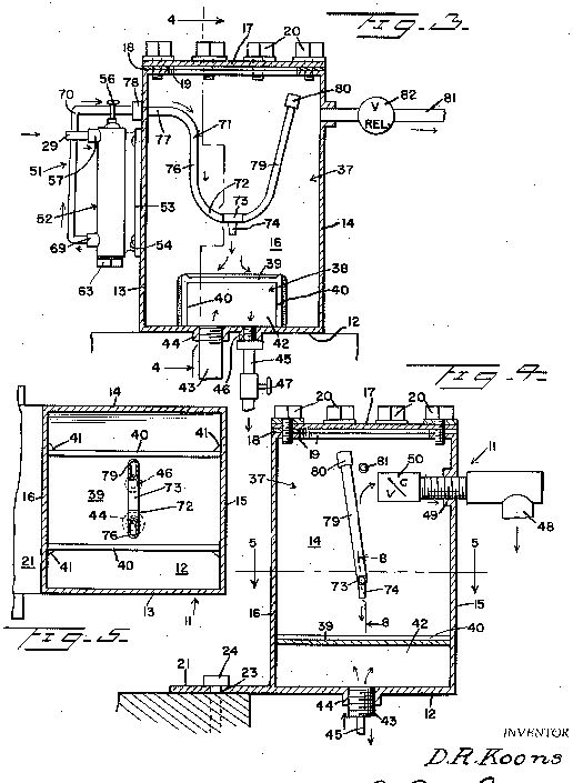
Fig. 1 is an elevational view of a vapor fuel system embodying the invention;
Fig. 2 is an enlarged view, partly in section, showing the carburetor forming a part of the system shown in Fig. 1;
Fig. 3 is a transverse sectional view on line 33 of Fig. 2;
Fig. 4 is a transverse sectional view on the line 4-4 of Fig. 2; and
Fig. 5 is a transverse sectional view on the line 5-5 of Fig. 2.
Referring more in detail to the drawings, wherein like parts are designated by like reference numerals, the reference numeral is used to generally designate a vapor fuel system embodying the invention.
The vapor fuel system 10 includes a conduit 11 which is connected to the gasoline tank for the internal combustion engine at one end and to a carburetor 12 at the opposite end. Interpolated in the conduit 11 is a gasoline filter 13 and an electric fuel pump 14. A wire 15 grounds the pump 14 and a wire 16 connects the pump 14 to a gasoline gauge 18 on which is mounted a switch 17 which is connected to the conduit 11 when it is connected to the carburetor 12. The gauge 17 is connected to a battery 19 of an internal combustion engine by a wire 20.
Switch 18 is of conventional construction and is of the type disclosed in United States Patents Nos. 2,894,093; 2,825,895; and 2,749,401. The switch is so constructed that a float in position in the gauge is acted on by the liquid therein. As the liquid rises the float will disengage a pair of contacts mounted in the gauge to cut off electric pump 14. As the float lowers due to the consumption of the liquid in the body the float will fall causing the contacts to be re-engaged to start pump 14 to replenish the liquid in the body.
The carburetor 12 includes a dome-shaped circular bowl or reservoir 21 which is provided with a centrally located flanged opening 22 whereby the reservoir 21 is mounted on a tubular throat 23. An apertured collar 24 on the lower end of the throat 23 is positioned on the Patented May 2, 1961 and fastening elements 27 secure the collar to the manifold 25 in fixed relation thereto.
A vapor control butterfly valve 28 is pivotally mounted in the ,lower end of the throat 23 and the valve 28 controls the entrance of the vapor into the internal combustion engine 26 and thus controls the speed of the internal combustion engine 26.
A raw gasoline pump 29 having an inlet 30 is mounted in the bottom of the reservoir 21 so that the inlet 30 communicates with the interior of the reservoir ,21. A spurt or feed pipe 31 connected to the pump 29 extends into the throat 23 so that by means of a linkage 32 that is connected to the pump 29 and to a linkage for the control valve 28 and the foot throttle of the internal combustion engine 26,.raw gas may be forced into the throat 23 to start the internal combustion engine 26 when it is, cold. 7 g a v The upper end of the throat 23 is turned over upon itself to provide a bulbous hollow portion 33- within the reservoir 21.
An immersion heater 34 is positioned in the bottom, of the reservoir 21 and a wire 35 grounds the heater 34. A thermostat 36 is mounted in the wall of the reservoir 21 and extendsinto the reservoir 21. *A, wire 37 connects the thermostat to the heater 34, and a wire 38 connects the thermostat 36 to a control 39 for the thermostat 36. A wire 40 connects the control 39 to the ignition switch 41 and the ignition switch 41 is in turn connected to the wire 20 that is connected to the battery 19 by a wire 42.
A-pair of relatively spaced parallel perforated baffle plates 43 and 44 are connected to the bulbous portion 33 on the upper end of the throat 23 and a second pair of perforated bafiie plates 45 and 46 extend inwardly from the wall of the reservoir 21 in parallel spaced relation to each other and to the baffle plates 43 and 44.
The baflie plates are arranged in staggered relation to each other so that the baflfle plate 45 is intermediate of the bafile plates 43 and 44 and the bafile plate 46 extends over the baffle plate 44.
The baflle plate 45 is provided with a central opening 47 and the baflle plate 46 is provided with a central opening 48 that is of greater diameter than the opening 47 in the balfle plate 44.
The domed top 49 of the reservoir 21 extends into a tubular air intake 50 that extends downwardly into the throat 23 and a mounting ring 51 is mounted on the exterior of the domed top 49 of the reservoir 21 in vertical alinement with the intake 50. An air cleaner 52 is mounted on the mounting ring 51 by a coupling 53 as is the usual procedure and a spider 54 is mounted in the upper end of the mounting ring 51 to break up the air as it enters the ring 51 from the air cleaner 52.
In operation and with the carburetor 12 mounted on the internal combustion engine in lieu of a conventional carburetor, the ignition switch 41 is turned on. Current from the battery 19' will cause the pump 14 to bring gasoline into the reservoir 21 until the switch 18 cuts off the pump 14 when the gasoline A has reached the level B in the reservoir 21. The control 39 is adjusted so that the thermostat 36 will operate the heater 34 until the gasoline A has reached a temperature of at which time the heater 34 will be cut ofi. When the gasoline A has reached the proper temperature, vapor raw gasoline to enter the intake manifold 25 until the vapors from the carburetor are drawn into the manifold 25 to cause the internal combustion engine 26 to operate.
As the gasoline A is consumed the pump 14 will again be operated and the heater 34 will be operated by the thermostat 36. Thus the operation as described will continue as long as the internal combustion engine is operating and the ignition switch 41 is turned on. The reservoir 12 will hold from 2 to 3 quarts of gasoline and since only the vapors from the heated gasoline will cause the carburetor 12 to run the internal combustion engine 26, the internal combustion engine will operate for a long time before more gasoline is drawn into the reservoir 21.
The baffles 43, 44, 45 and 46 are arranged in staggered relation to prevent splashing of the gasoline within the carburetor. The level B of the gasoline A in the reservoir 21 is maintained constant by the switch 18 and with all elements properly sealed, the vapor fuel system 10 will efficiently operate the internal combustion engine 26.
The valve 28, controlling the entrance of vapors into the intake manifold 25, controls the speed of the internal combustion engine in the same manner as the control valve in a conventional carburetor.
There has thus been described a vapor fuel system embodying the invention and it is believed that the structure and operation thereof will be apparent to those skilled in the art, it is also to be understood that changes in the minor details of construction, arrangement and combination of parts may be resorted to provided they fall within the spirit of the invention and the scope of the appended claim.
US3294381
CARBURETOR
This invention relates to a carburetor construction.
An object of the present invention is to provide a carburetor in which the fuel, before the same is combined With air and fed to an internal combustion engine, is treated by the hot exhaust fumes of said engine to increase its burning efficiency in the cylinders of said engine.
Another object of the invention is to provide a carburetor, as above characterized, that circulates the fumes-laden fuel in a manner to free the same of inordinately large globules of fuel, thereby insuring that only finely divided and pre-heated fuel of mist-like consistency is directed to the engine intake manifold.
The present carburetor, when used for-feeding the cylinders of a six-cylinder engine of a popular automobile, improved the miles per gallon performance of said engine, during ordinary driving conditions, over 200%, a common grade of gasoline being used, the efficiency achieved resulting from the mentioned pre-heating of the fuel and because the same is kept under low pressure imposed by suction applied to the carburetor for the particular purpose of maintaining the level of fuel constant during engine operation. Such low pressure in the carburetor causes increased vaporization of the fuel in the carburetor and increased efficiency of operation.
This invention also has for its objects to provide such means that are positive in operation, convenient in use, easily installed in a working position and easily disconnected therefrom, economical of manufacture, relatively simple, and of general superiority and serviceability.
The invention also comprises novel details of construction and novel combinations and arrangements of parts, which Will more fully appear in the course of the following description, and which is based on the accompanying drawing. However, said drawings merely shows and the following description merely describes, one embodiment of the present invention, which is given by way of illustration or example only.
In the drawing, like reference characters designate similar parts in the several views.
FIG. 1 is a partly broken plan view of a carburetor according to the present invention, the same being shown in operative association With a fuel supply, feeding and return system.
FIG. 2 is a vertical sectional view of the carburetor as taken on the plane of lime 22 of FIG. 1.
FIG. 3 is a partial side elevation and partial sectional view of said carburetor showing additional structural details.
The present carburetor is preferably mounted on the usual downdraft air tube 5 that receives a flow of air from atmosphere by way of an air cleaner, said tube 5, in any usual way, being provided With a throttle or butterfly valve that controls flow and is formed to have a flow-increasing Venturi passage. The above common features of the fuel feed to the intake manifold of an internal combustion engine are not shown; first, because the same are old and well known and, second, the same are disclosed in applicants pending application, Serial No. 182,420, bearing the same title, now abandoned. The present carburetor embodies improvements over the disclosure of the earlier application.
The present carburetor comprises a housing 6 mounted on said air tube 5, and designed to hold a shallow pool of fuel 7, a fuel inlet 8 terminating in a spray nozzle 9, an exhaust gas manifold 10 to conduct heated exhaust gases for discharge into the spray of fuel emanating from the nozzle 9 and for heating said pool of fuel 7, means 11 to scrub the fuel-fumes mixture to eliminate large droplets of fuel from said mixture (which fall into the pool 7 therebeneath), a nozzle tube 12 receptive of said scrubbed mixture and passing the same under Venturi action into air tube 5 combined With air in said tube for passage to the intake manifold of an engine, and a pickup pipe 13 connected to an outlet 14 for drawing excess fuel from the pool 7 during operation of the carburetor.
The system connected to said carburetor is shown in FIG. 1, and comprises a fuel tank 15, a generally conventional fuel pump 16 for drawing fuel from said tank and directing the same to the inlet S, a fuel filter 17, and a pump 18 connected in series between said tank and the outlet 14 to place the pipe 13 under suction and to draw excess gasoline in the carburetor back to the tank 15 for re-circulation to the inlet 8.
The carburetor housing 6 may be circular, as shown, and quite fiat compared to the diametral size, so as to have a large fiat bottom 20 that, With the cylindrical wall 21, holds the fuel pool 7. A cover 22 encloses the top of the housing. The bottom 20 and cover 22 have aligned central openings through which the down draft tube 5 extends, said pipe thereby forming the interior of the housing to have an annular inner space 23.
The fuel inlet 8 is separably secured to the cover 22 With the spray nozzle 9 thereof extending through said cover. While shown With spray-emitting holes 24 arranged to provide a spray around the nozzle 7, the nozzle may be formed so the spray is directional as desired, for most efficient inter-engagement of the sprayed fuel with the heating gases supplied by the manifold 10.
Said manifold is shown as a pipe 25 that has an end 26 extending from the conventional heat riser chamber) not shown) of the engine that is being supplied with fuel by the present carburetor, the arrow 27 indicating exhaust gas flow into the pipe 25. Said pipe may encircle the lower portion of the housing 6 to, thereby, heat the pool 7 by transfer of heat through the wall of the housing. Said manifold pipe is shown with a discharge end 28 that extends into the housing in an inward and upward direction toward the nozzle 9 so that the exhaust gases flowing in said pipe intermingle With the sprayed fuel to heat the same as the fuel leaves the nozzle.
The fuel-scrubbing means 11 is shown as an arcuate chamber 29 disposed within the housing 6, the same being provided With a complement of baffle walls 30 that causes the flow of fumes-heated misty fuel to follow a serpentine path that intercepts the heavier globules of fuel so the same may run down the faces of said walls, through openings 31 in the bottom wall 32 of the scrubbing chamber 29, and into the pool 7. Thus, only the finer globules of the heated fuel emanate from the open end 33 of the chamber 29 into the interior space 23 of the housing 6 above the level of the pool 7. This fuel, by the suction action thereon through the nozzle tube 12 due to the Venturi action in the downdraft tube 5, is drawn into the air flow in the latter tube to carburize said flow of air. The same then proceeds to the engine for combustion therein in the usual manner.
The pickup pipe 13 is also shown as carried by the housing cover 22 and may be adjusted so its lower open end is so spaced from the housing bottom 20 as to regulate the depth of the pool 7, which is preferably below the bottom wall 32 of the scrubbing chamber 29. Since this pipe is subject to the suction of the pump 18 through the outlet 14 and filter 17, the level of the pool 7 is maintained by a return to the tank 15 of excess fuel for subsequent pre-heating and scrubbing, as above described, when fed by pump 16 to the nozzle 9.
US3653643
CARBURETOR
A carburetor including a housing having a fluid fuel reservoir in the bottom, an air inlet at the top of the housing, a delivery pipe coaxially mounted within the housing and terminating short of the top of the housing, and a porous vaporizing filter substantially filling the reservoir. A baffle is concentrically mounted within said housing and extends partially into the vaporizing filter in the reservoir to deflect the incoming air through the vaporizing filter. The level of liquid fuel in the reservoir is kept above the bottom of the baffle, so that air entering the carburetor through the inlet must pass through the liquid fuel and vaporizing filter in the reservoir before discharge through the outlet. A secondary air inlet is provided in the top of the housing for controlling the fuel air ratio of the vaporized fuel passing into the delivery pipe.
BACKGROUND OF THE INVENTION
It is generally well known that liquid fuel must be vaporized in order to obtain complete combustion. Incomplete combustion of fuel in internal combustion engines is a major cause of air pollution. In a typical automotive carburetor, the liquid fuel is atomized and injected into the air stream in a manifold of approximately 3.14 sq. in. cross section. In an 8 cylinder 283 cu. in. engine running at approximately 50 miles per hour, the engine operates at approximately 2,400 r.p.m. and requires approximately 340,000 cu. in. of air per minute. The air velocity at this speed in the intake manifold will be approximately 150 feet per second and it will therefore take approximately 0.070 of a second for a particle of fuel to move from the carburetor to the combustion chamber. The fuel will remain in the combustion chamber for approximately 0.0025 seconds when operating at 2,400 r.p.m.
It is conceivable that in this short period of time complete vaporization of the fuel is not achieved and as a consequence, incomplete combustion occurs resulting in further air pollution. The liquid fuel particles if not vaporized can deposit on the cylinder walls and dilute the lubricating oil or oil film on the walls of the cylinders promoting partial burning of the lubricating oil and adding further to the pollution problem. Destruction of the film of lubricating oil by combustion can also increase mechanical wear between the piston and cylinder.
SUMMARY OF THE INVENTION
The carburetor of this invention provides for the complete combustion of liquid fuel in an internal combustion engine with a corresponding decrease of air pollutant in the exhaust. This is achieved by supplying a completely vaporized or dry gas to the combustion chamber. The primary air is initially filtered prior to passing through a vaporizing filter which is immersed in liquid fuel provided in a reservoir in the carburetor. The vaporizing filter continuously breaks the primary air up into small bubbles thereby increasing the surface area available for evaporation of the liquid fuel. Secondary air is added to the enriched fuel-air mixture through a secondary air filter prior to admission of the fuel-air mixture into the combustion chamber of the engine. Initial filtration of both the primary and secondary air removes any foreign particles which may be present in the air which could cause increased wear within the engine. The carburetor also assures delivery of a clean dry gas to the engine due to the gravity separation of any liquid or dirt particles from the fuel enriched primary air.
Other objects and advantages will become apparent from the following detailed description when read in connection with the accompanying drawing, in which the single figure shows a perspective cross sectional view of the carburetor of this invention.
DESCRIPTION OF THE INVENTION
The carburetor 40 disclosed herein is adapted for use in an internal combustion engine wherein air is drawn through the carburetor to vaporize the fuel in the carburetor prior to admission to the combustion chamber.
In this regard, the flow of liquid fuel, gas or oil, to the carburetor 40 is controlled by means of a float valve assembly 10 connected to a source of liquid fuel by a liquid fuel line 12 and to the carburetor 40 by a connecting tube 14. The flow of liquid fuel through the float valve assembly 10 is controlled by a float 16 pivotally mounted within a float chamber 18 and operatively connected to a float valve 20.
In accordance with the invention, the liquid fuel admitted to the carburetor 40 through tube 14 is completely evaporated by the primary air for the engine within the carburetor 40 and mixed with secondary air prior to admission into a delivery tube 100 which is connected to the manifold 102 of the engine. More specifically the carburetor 40 includes a cylindrical housing or pan 42 having a bottom wall 44 which forms a liquid fuel and filter reservoir 46. A vaporizing filter 48 is positioned within the reservoir 46 and extends upward a distance from the bottom wall 44 of the housing 42. The vaporizing filter 48 is used to continuously break up the primary air into a large number of small bubbles as the primary air passes through the liquid fuel in the reservoir 46. This increases the surface area per volume of air available for evaporation of the liquid fuel, as more particularly described hereinafter. This filter 48 is formed of a three-dimensional skeletal material that is washable and is not subject to break-down under the operating conditions of the carburetor. A foamed cellular plastic polyurethane filter having approximately 10 to 20 pores per inch has been used successfully in the carburetor 40.
The housing 42 is closed at the top by a hood or cover 50 which can be secured thereto by an appropriate means. The hood 50 has a larger diameter than the diameter of the housing 42 and includes a depending flange 52 and a depending baffle 54. The flange 52 is concentrically arranged and spaced outwardly from the outer surface of the housing 42 to form a primary air inlet 56. The baffle 54 is concentrically arranged within the housing 42 to define a primary air chamber 58 and a central mixing chamber 60 within the housing 42.
Primary air is drawn into the housing 42 through the air inlet 56 and is filtered by means of a primary air filter 62 which is removeably mounted in the space between the flange 52 and the wall of the housing 42. The primary air filter 62 is prevented from being drawn into the housing 42 by means of a screen 64. The primary air filter 62 can be made of the same filtering material as the vaporizing filter 48.
The primary air as it enters the primary air chamber 58 is deflected through the liquid fuel in the reservoir 46 by means of the cylindrical baffle 54. The baffle 54 extends downwardly from the hood 50 far enough to penetrate the upper portion of the vaporizing filter 48. The primary air must pass around the bottom of the baffle 54 and through both the liquid fuel and the vaporizing filter 48 prior to entering the mixing chamber 60.
The level of the liquid fuel in the reservoir 46 is maintained above the bottom edge of the baffle 54 by means of the float valve assembly 10. The operation of the float valve assembly 10 is well known. The float chamber 18 is located at approximately the same elevation as the reservoir 46 and the float 16 pivots in response to a change in the level of the liquid fuel in the float chamber to open the float valve 20.
One of the important features of the present invention is the efficiency of evaporation of the liquid fuel by the flow of the large number of bubbles through the reservoir. This is believed to be caused by the continual break up of the bubbles as they pass through the vaporizing filter 48. It is well known that the rate of evaporation by a bubble of air passing through a liquid unmolested is relatively slow due to the surface tension of the bubble. However, if the bubble is continuously broken, the surface tension of the bubble is reduced and a continual evaporating process occurs. This phenomenon is believed to be the cause of the high evaporation rate of the liquid fuel in the carburetor of this invention.
Another feature of the carburetor of this invention is the ability of the carburetor to supply dry gas to the central mixing chamber 60 in the housing 42. Since the flow of primary air in the central mixing chamber 60 is vertically upward, the force of gravity will prevent any droplets of liquid fuel from rising high enough in the carburetor to enter the delivery tube 100. The delivery of dry gas to the delivery tube increases the efficiency of combustion and thereby reduces the amount of unburned gases or pollutants that are exhausted from the engine into the air.
Means are provided for admitting secondary air into the central mixing chamber 60 to achieve the proper fuel-air ratio required for complete combustion. Such means is in the form of a secondary air filter assembly 80 mounted on an inlet tube 82 provided in an opening 84 in the hood 50. The secondary air filter assembly 80 includes an upper plate 86, a lower plate 88, and a secondary air filter 90 positioned between the plates 86 and 88. The secondary air filter 90 is prevented from being drawn into the inlet tube 82 by means of a cylindrical screen 92 which forms a continuation of the tube 82. The secondary air passes through the outer periphery of the secondary air filter 90 through the screen 92 and into the tube 82. The flow of secondary air through the tube 82 is controlled by means of a butterfly valve 94 as is generally understood in the art.
Complete mixing of the dry gas enriched primary air with the incoming secondary air within the housing 42 is achieved by means of a turbulator or deflector 96 positioned at the end of the tube 82. The turbulator 96 includes a number of vanes 98 which are twisted to provide an outwardly directed circular air flow into the central mixing chamber 60 and thereby creating an increase in the turbulence of the secondary air as it combines with the fuel enriched primary air. The turbulator prevents cavitation from occurring at the upper end of the outlet or delivery tube 100.
The flow of fuel-air mixture to the engine is controlled by means of a throttle valve 104 provided in the outlet or delivery tube 100. The operation of the throttle valve 104 and butterfly valve 94 are both controlled in a conventional manner.
THE OPERATION OF THE CARBURETOR
Primary air is drawn into the housing 42 through the primary air inlet 56 and passes upwardly through the primary air filter 62 where substantially all foreign particles are removed from the primary air. The filtered primary air flows downward through the primary air chamber 58, under the baffle 54, through the fuel filter reservoir 46, and upward into the central mixing chamber 60. All of the primary air passes through the vaporizing filter 48 provided in the reservoir 46. The vaporizing filter 48 continuously breaks the primary air stream into thousands of small bubbles reducing surface tension and increasing the air surface area available for evaporization of the liquid fuel. Since the outside surface of each bubble is being continuously broken up by the vaporizing filter 48 and is in constant contact with the liquid fuel as the bubble passes through the vaporizing filter 48, there is a greater opportunity for evaporization of the fuel prior to entering the central mixing chamber 60 in the housing 42. The vertical upward flow of the fuel enriched primary air in the central mixing chamber assures that no liquid fuel droplets will be carried into the delivery tube 100.
The fuel enriched primary air is thoroughly mixed with the secondary air entering through tube 82 by means of the turbulator 96 which increases the turbulence of the primary and secondary air within the central mixing chamber and prevents cavitation from occurring in the delivery tube 100. The completely mixed fuel enriched primary air and the secondary air then passes through the delivery tube 100 into the combustion chamber of the engine.
US2761660
Fuel saving attachment for an internal combustion engine
This invention relates to a novel unit which may be readily attached to an internal-combustion engine and which provides a bypass between the gasoline storage tank and the engine carburetor by which the gasoline is bypassed to the engine around the carburetor and wherein the gasoline is preheated and converted from a liquid into a gaseous state before entering the engine.
More, particularly, it is an aim of the present invention to provide a unit through the use of which an internal-combustion engine may be efficiently operated with less fuel consumption than by the use of a conventional carburetor.
Another object of the invention is to provide a unit having novel means for regulating the supply of the raw gasoline thereto and whereby the gasoline as it is supplied to the heating chamber of the unit will thus be quickly converted into a gaseous state before passing from the unit into the engine.
Another object of the invention is to provide means to prevent the building up of an excessive pressure of the vaporized fuel in the. vaporizing chamber.
Still a further object of the invention is to provide a unit having means for regulating the temperature of the vaporizing chamber for thereby partially regulating the rate of flow of the raw fuel thereto.
Still another object of the invention is to provide a unit having novel means to prevent an explosion in the vaporizing chamber in the event of an engine backfire.
Still another object. of the invention is to provide a unit having; a vaporizing chamber heated by exhaust gases from the exhaust manifold.
Various other objects and advantages of the invention will hereinafter become more fully apparent from the following description of the drawings, illustrating a presently preferred embodiment thereof, and wherein:
Figure 1 is a fragmentary top plan view of an internal combustion engine and showing the fuel saving unit, in top plan, applied thereto;
Figure 2 is a side elevational view of said unit and a portion of the engine;
Figure 3 is an enlarged sectional view, partly in elevation, taken substantially along a plane as indicated by. the line 33 of Figure 1;
Figure 4 is a vertical sectional view: taken. through the vaporizing chamber, substantially along a plane as indicated. by the line 44 of. Figure 3;
Figure 5 is. a horizontal sectional view through the vaporizing chamber, taken substantially along a plane as indicated by the line 55 of Figure 4;
Figure 6 is a fragmentary side elevational view on an enlarged scale of a portion of the vaporizing chamber, looking from left to right of Figure 3;
Figure 7 is an enlarged, vertical sectional view taken substantially-along a plane, as indicated by the line 77 of Figure 6, and
Figure. 8 is an enlarged fragmentary vertical sectional view taken substantially along a plane as indicated by the line 8'8 of Figure 4.

Referring more specifically to the drawings, the fuel saver attachment in its entirety and comprising the invention is designated generally 10 and includes a boxlike container, designated generally 11, which is preferably formed of steel and preferably provided with a copper coated inner surface. The box-like container 11 includes a bottom wall 12, a front wall 13, a rear wall 14, an outer side wall 15 and an inner side wall 16. The container 11 may be of any desired size and any desired shape in cross section. The container 11 also includes a removable top wall or cover 17, the marginal portions of which rest on a. gasket 18 which is disposed between said cover portions and inturned flanges 19 of the walls 13, 14, 15 and' 16. The top wall or cover 17 is detachably secured in position by fastenings 20 which extend therethrough, through the gasket 18 and are threadedly secured to the flanges 19 and which fastenings are tightened so that the gasket 18 will seal the joint between the flanges 19 and the top wall or cover 17. The bottom 12 is provided with an extension forming a bracket 21 which is adapted to rest on a part of an internal-combustion engine 22 and which is provided with elongated slots or openings 23 for receiving fastenings 24 by means of which the box or container 11 is demountably supported on the engine in substantially an upright position. The container 11 is preferably mounted outwardly with respect to one side of the engine 22 and above and adjacent a portion of the exhaust manifold 25 of the engine. The container 11 is also preferably mounted behind and adjacent the conventional engine carburetor 26 and also adjacent to the intake manifold 27, as seen in Figures 1 and 2.
Gasoline is supplied to the carburetor 26 from a storage tank, not shown, through a conduit or pipe 28. A branch conduit 29 communicates with and leads from the supply conduit 28, adjacent the container 11 and has a conventional filter 36 interposed therein. A manually actuated shutoff valve 31, of any conventional construction, is mounted in the fuel supply conduit 28 between the branch conduit 29 and the carburetor 26 and is adapted to be opened and closed by swinging movement of an actuating lever 32 which is connected thereto and to which a link 33 is connected. A similar manually actuated shutoff valve 34 is mounted in the branch conduit 29 adjacent the supply conduit 28 and is similarly actuated by a lever 35 and a link 36. The links 33 and 36 extend in the same direction from the levers 32 and 35 and are adapted to be manually actuated from a point remote from the unit 10, as for example, from the dashboard of a motor vehicle, not shown.
As seen in Figures 3, 4 and 5, the box-like container 11 has a hollow interior defining a vaporizing chamber, designated generally 37, in the lower part of which is disposed a heating unit, designated generally 38. The heating unit 38 comprises a top wall or plate 39- and side walls 40. The walls 40 are disposed in upright positions on the bottom 12 between and spaced from the walls 13 and 14 and extend between and are secured at their ends to the walls 15 and 16. Said walls 40 are secured to the walls 12, 15 and 16, as by welding as seen at 41, and the top wall 39 is disposed between and suitably secured to upper portions of the walls 40 and is likewise secured, as by welding, to the side walls 15 and 16. The walls 39 and 40 cooperate with a portion of the bottom 12 and walls 15 and 16, disposed between said walls 40, in, forming a heating chamber 42 of the heat ing unit 38 which is sealed off from the vaporizing chamber 37. A conduit 43 has one end connected to a boss 44 formed in the bottom 12 and opens into the heating chamber 42 and a second smaller conduit 45 has one end connected to a boss 46 of the bottom 12 and likewise communicates with the heating chamber 42. As best seen in Figure 2, the other end of the conduit 43 is tapped into the exhaust manifold 25, adjacent the container 11, and the opposite end of the conduit 45 is tapped into the intake manifold 27, adjacent the carburetor 26. Said conduit 45 is provided with a manually controlled shutoff valve 47. A conduit 48 has a portion extending through and having sealing engagement in a boss 49 of the side wall and has one end disposed in and in communication with the vaporizing chamber 37. The conduit 48 is provided with an outwardly opening check valve 50 located adjacent the inlet end thereof, which is disposed in the chamber 37. The opposite outlet end of the conduit 48 is tapped into the intake manifold 27, preferably adjacent the last mentioned outlet end of the conduit 45, as seen in Figures 1 and 2.
A regulating valve unit, designated generally 51, includes an elongated valve housing 52, preferably of cylindrical shape in cross section. The housing 52 has an integral bracket portion 53 which is secured against the outer side of the wall 13 by fastenings 54. One end of the housing 52 is closed except for a threaded boss 55 through which the threaded stem of a needle valve 56 threadedly extends inwardly of the valve housing and axially thereof. The valve housing 52 adjacent said aforementioned end is provided with an intake port 57 which opens into a chamber 58 in said valve housing, between said aforementioned housing end and a valve seat 59, which is disposed in the valve housing 52, adjacent said housing end. The other, outlet end of the branch conduit 29 is connected to said inlet port 57 and opens into the chamber 58. The valve seat 59, as seen in Figure 7, constitutes a substantially conical partition which projects generally toward the aforementioned housing end and which has a tapered center port 60 which is tapered away from the chamber 58 and which provides a seat for the adjacent tapered end 61 of the needle valve 56, which is disposed in the chamber 58.
The valve housing 52 has an internally threaded open opposite end 62 which is located remote from the valve seat or partition 59 and which is normally closed by a threaded plug 63 having an inwardly projecting stem 64. An expansion coil spring 65 has one end disposed against the inner end of the plug 63 and mounted loosely around its stem 64. The spring 65 is loosely disposed within the valve housing 52 and extends from the plug 63 to adjacent the valve seat 59. A valve stem 66 engages in the opposite end of the expansion spring 65 and has a head against which the opposite end of said spring 65 bears and which head is disposed between the last mentioned spring end and the concave side of the valve seat 59. The outer side of said valve head 67 which faces the valve seat 59 is shaped to conformably seat against the concave side thereof for sealing the valve chamber 58 from the larger chamber 68 of the valve housing in which the spring 65 and valve 66, 67 are disposed. The
housing 52 is provided with an outlet port 69 which communicates with the valve chamber 68 adjacent the threaded housing end 62 and to which is connected one end of a conduit 70 which communicates with said chamber 68.
A tube 71 of relatively small cross sectional size and preferably formed of brass is disposed within the upper part of the vaporizing chamber 37 and includes a bottom portion 72 which is disposed above and spaced from the top plate 39 of the heating unit 38. Said bottom portion 72, as best seen in Figure 8, is preferably divided intermediate of its ends and a sleeve portion 73, of substantially the same external and internal diameter as the tube 71, is interposed therein, in any suitable manner as by a sweat fit connection. Said inserted sleeve 73 intermediate of its ends is provided with a depending nozzle 74 having a bore 75 which tapers in cross sectional size toward its lower outlet end and the larger inner end of which is substantially smaller than the bore of the tube 71 and sleeve 73. One end of the tube 71 defines an upwardly extending leg 76 of the bottom portion 72 which has an outturned upper portion 77 which extends through the wall 13, near to but spaced from the upper end of the vaporizing chamber 37 and which is connected to the other end of the conduit 70 by a coupling 78. The other leg 79 of the tube 71 extends upwardly from the other end of the bottom portion 72 to adjacent the upper end of the vaporizing chamber 37 and to above the level of the opposite inlet end portion 77 of said tube. The open upper end of the tube end 77 is closed and sealed by a cap 80 which may be secured detachably thereon in any suitable manner as by a threaded connection. As seen in Figures 3 and 4, the tube 71 supports the nozzle 74 above and spaced from the top plate 39 of the heating unit and so that said nozzle discharges downwardly and toward said top plate.
A conduit 81 has one end connected to the rear wall 14 and communicating with the upper portion of the chamber 37 and the opposite end thereof, not shown, is adapted to open into the gasoline storage tank. The tube 81 contains a relief valve 82.
A small metal ball or sphere 83, constituting a valve, is mounted in the tube 71 or sleeve 73 and is of a diameter to seat on and close the enlarged upper inlet end of the nozzle bore 75 and is of substantially smaller diameter than the bore of the tube 71 or sleeve 73 but of considerably larger diameter than the enlarged inlet upper end of the nozzle bore 75, as clearly illustrated in Figure 8. In this figure the steel ball valve 83 is shown in a closed position.
When initially starting the engine 22, assuming that the engine is cold, the valve 31 is opened and the valve 34 is closed so that gasoline is supplied to the engine through the carburetor 26 in a conventional manner. The engine 22 is then operated in a conventional manner until it has had an opportunity to warm up to substantially a normal operating temperature. The links 33 and 36 are then operated manually for closing the valve 31 and opening the valve 34. The supply of gasoline to the carburetor through the line 28 will thus be cut off while gasoline will flow through the branch conduit 29 into the inlet chamber 58 of the valve 51. The needle valve 56 is set so that a proper amount of fuel or gasoline can pass through the passage 60 from the chamber 58 to the chamber 68 when the valve 67 is in an open position, which amount will vary depending upon the size of the engine 22. Accordingly, after the needle valve 56 has once been properly set no further adjustment thereof is required. The spring is relatively weak so that the pressure of the liquid fuel in the chamber 58 will displace the valve 67 downwardly to allow the fuel to pass through the valve port 60, through the valve chamber 68 and conduit into the tube 71. The valve 47 will be in a partially open position having been previously set to maintain a proper temperature in the heating chamber 42 and, accordingly, like the needle valve 56 will always be maintained in a properly adjusted open position. Accordingly, at the time that the liquid fuel is supplied to the tube 71 the chamber 42 will have been previously heated by the hot exhaust gases which are drawn into said chamber 42 through the conduit 43 from the exhaust manifold 25 by the suction supplied to the chamber 42 through the conduit 45 from the intake manifold 27. Thus, hot exhaust gases will be continuously drawn into the heating chamber 42 and the cooler gases extracted therefrom and discharged into the intake manifold 27, this constituting only a small part of the exhaust gases passing through the exhaust manifold 25. Thus, the vaporizing chamber 37 will have been substantially heated when the liquid fuel is initially admitted to the tube 71.
As the liquid fuel flows down the leg 76 of the tube 71 and into the sleeve 73 it will strike the ball valve 83 and unseat said ball valve from the iet bore 75 and force the ball valve 83 to the right as seen in Figure 8 toward the other tube leg 79. Accordingly, a part of the gasoline or liquid fuel will escape downwardly through the nozzle 74 and will be discharged in the form of a fine jet toward the heated top plate 39 and upon striking said plate will be instantly vaporized. The vaporized fuel will fill the vaporizing chamber 37 and a part thereof will be drawn through the outlet conduit 48 by the suction therein supplied from the intake manifold 27. The outwardly opening check valve 50 of the supply conduit 48 will open away from the vaporizing chamber 37 primarily in response to the suction in the conduit 48 and Will not be opened by the pressure in the vaporizing chamber 37 alone. The check valve 50 additionally functions to close automatically to prevent a backfire in the engine 22 discharging into the vapor chamber 37 through the conduit 48.
The liquid fuel flowing down the tube leg 76 and into the sleeve 73 will maintain the valve 83 in an open position until the heat within the vaporizing chamber 37 heats the fuel which has passed the valve 83 and is in the tube leg 79 sufficiently to vaporize the fuel in the leg '79 for creating a back pressure in said tube 71. When this occurs, the ball valve 83 will be forced back into the sleeve 73 and will resume its closed position as seen in Figure 8, preventing further escape of the liquid fuel into the vaporizing chamber 37, so that the pressure in the chamber 37 will be diminished as the vaporized fuel is removed therefrom through the conduit 48. The fact that the tube leg '79 extends to above the tube leg 76 and is located more remote from the supply of cool gasoline to the tube 71 from the conduit 70, will cause a greater pressure to be initially developed in the tube end 79 than in the leg 76 for closing the valve 83. However, the liquid fuel Will also be vaporized in the tube portions 72, 76 and 77 and also in the sleeve 73 so that when the valve is moved to a closed position as seen in Figure 8 a sufficient back pressure will be created by the vaporized fuel in the tube 71 to produce a pressure in the supply conduit 70 and valve chamber 68 which, in combination with the spring 65 will be adequate to overcome the pressure in the chamber 58 for displacing the valve 67 into a closed position against the valve seat 59 to thus shut off the supply of liquid fuel to the tube 71. Thereafter, as the vaporized fuel is removed from the vaporizing chamber 37 through the conduit 48 the heat in the chamber 37 will be diminished thereby permitting the fuel to cool and liquefy in the tube 71. This will reduce the pressure in the chamber 68 so that the pressure of the fuel in the chamber 58 will again be sufficient to overcome the pressure of the valve 65 to reopen the metering port 60 for supplying additional liquid fuel to the tube 71, as previously described. When this occurs, the ball valve 83 will again be displaced to the right as seen in Figure 8 from its closed position, in the manner as previously described, so that additional fuel will be discharged from the nozzle 74 toward the heating unit 38 to replenish the supply of vaporized fuel in the chamber 37. The aforedescribed operation will be repeated intermittently while the engine is in operation. From time to time too great a pressure may develop in the chamber 37, as for example if the engine 22 is permitted to idle for a considerable period of time. When this occurs, the excess pressure will cause the relief valve 82 to open so that the excess of the vaporized fuel can escape from the chamber 37 through the conduit 81 into the fuel storage tank wherein the fuel will be readily liquefied.
Due to the fact that the tube 71 contains a much greater percentage of fuel in comparison to the capacity of its bore than the chamber 37, the pressure of the vaporized fuel therein will always be substantially greater than the pressure in the chamber 37 so that a back pressure cannot be developed in the nozzle bore 75 from 6 the chamber 37, sufficient to unseat the ball valve 83, as the relief valve 82 will open before this could occur.
From the foregoing, it will 'be seen that vaporized fuel will be supplied to the engine 22 directly through the intake manifold 27 and this vaporized fuel will function much more efficiently than liquid fuel supplied directly to the carburetor 26 so that when the attachment or unit 10 is in operation and the valve 31 is closed, the engine 22 will operate with much greater power and efficiency and with a greatly reduced fuel consumption. The accelerator is utilized in a conventional manner when the unit 10 is employed for regulating the supply of air through the carburetor to the intake manifold 27 and which is mixed with the vaporized fuel supplied to the intake manifold through the conduit 48 for thus regulating the speed of operation of the engine 22.
Before stopping operation of the engine 22, when operation thereof is to be interrupted for a sufficient time to permit the engine to cool, the links 33 and 36 are again manually actuated to close the valve 34 and open the valve 31 so that gasoline or liquid fuel will be again supplied to the engine through the carburetor 26 before operation of the engine is interrupted and so that the engine can thereafter be started in a conventional manner and as previously described.
US4458653 / US4506647
Vapor fuel system for internal combustion engines
A vapor fuel system for an internal combustion engine includes two vaporizing units for vaporizing liquid fuel and mixing it with air and a vapor heat exchanger for heating the fuel vapor-air mixture prior to its combustion in the engine. Hot fluid circulating in engine's cooling system flows through a jacket integrally surrounding each of the two vaporizing units and the vapor heat exchanger to provide a source of heat for vaporizing the fuel and heating the fuel vapor-air mixture. A fuel line carrying the liquid fuel to each of the vaporizing units passes through the hot fluid-filled jacket surrounding each of the units, thereby preheating the fuel before it is vaporized. In an alternate embodiment of the invention, two solenoid valves, one along the fuel line leading to each vaporizing unit, act in conjunction with a timing means to alternate periodically activation and deactivation of the vaporizing units.
BACKGROUND OF THE INVENTION
1. Field of the Invention
The present invention relates generally to fuel systems for internal combustion engines and more particularly to a method and apparatus for supplying a vaporized fuel to an internal combustion engine.
2. Description of the Prior Art
Fuel vapor systems which supply fuel vapor to an internal combustion engine are old in the art. Such systems are generally more fuel efficient than conventional liquid fuel systems because they deliver more spaced and uniformly spread fuel molecules to the combustion chamber, thereby promoting a shorter, more complete and hence, more efficient burn of the fuel.
Typical fuel vapor systems are disclosed in a number of U.S. patents, including Davison, et al. U.S. Pat. No. 4,216,751; Champ, U.S. Pat. No. 3,072,113; Cunningham, et al. U.S. Pat. No. 2,285,905; Pantano, U.S. Pat. No. 2,882,882, and Long, U.S. Pat. No. 1,970,010. In each of these systems raw liquid fuel is vaporized in a vaporization chamber heated by exhaust gases discharged from the engine. The fuel vapor is subsequently mixed with most, if not all, of the air needed for combustion and delivered to the engine.
These systems have a number of disadvantages. With the possible exception of Long, each of the above systems delivers liquid fuel at or close to ambient temperature to the vaporization chamber. Since the temperature of the fuel must be increased substantially to its vaporization temperature before vaporization will occur, a considerable amount of heat must be supplied. As a result, a significant percentage of the fuel delivered to the vaporization chamber never vaporizes and must be either returned to the fuel tank or delivered to the engine in liquid form, thereby reducing the fuel efficiency of the system. The Long system apparently preheats the liquid fuel in a primary heater pipe, but the amount of heat supplied appears to be minimal and not enough to alleviate the problem.
In each of the above systems, it is also quite likely that a significant percentage of the fuel vapor cools and condenses as it travels from the vaporization chamber to the engine, since the fuel vapor is at a temperature not much above its condensation temperature and little is done to prevent heat loss, other than perhaps insulating the fuel vapor line or making the line as short as possible. Such condensation also reduces the fuel efficiency of the fuel vapor system. The condensation problem is compounded in Davison, Cunningham and Champ where a full supplement of air at or close to ambient temperature is mixed with the fuel vapor shortly before combustion, thereby cooling and condensing even more of the vapor. The Pantano and Long vapor systems introduce a small quantity of air into the vaporization chamber to mix with the fuel while it is being vaporized. However, this alleviates the problem to only a slight extent since most of the air is mixed with the fuel after it has been vaporized.
Additionally, the exhaust gases used by the above systems to vaporize the fuel dissipate rapidly after the engine is shut off, thereby causing the manifold and exhaust pipes carrying the exhaust gases to cool down rapidly. Thus, once the engine is shut off the above systems are incapable of supplying sufficient heat to vaporize the fuel and start the engine. As a result, a conventional liquid fuel system must be used to start and warm up the engine, even when the engine has been shut off for only a few minutes.
Finally, while vapor systems generally achieve a shorter, more complete and less wasteful burn of the fuel than liquid fuel systems, the fuel-air mixture combusted is inherently leaner. Thus, vapor systems, such as those discussed above, generally cannot generate as much power as liquid systems. The power output of the vapor system can be increased by supplementing the fuel vapor with liquid fuel, but then the overall fuel efficiency is reduced.
Accordingly, there is a need for a fuel vapor system which reduces the amount of unvaporized fuel in the vaporization chamber, reduces the amount of fuel vapor condensation, is capable of starting and running the engine without the help of a supplementary fuel system shortly after the engine is shut off, and produces sufficient vapor to satisfy the power requirements of the engine under most conditions in a fuel efficient manner.
SUMMARY OF THE INVENTION
The present invention solves the foregoing problems and improves prior art fuel vapor systems by providing two selectively operable fuel vaporizing units in parallel fluid communication with a fuel tank and an internal combustion engine. Liquid fuel is pumped from the fuel tank to each vaporizing unit through a fuel line which passes through a fluid-filled jacket surrounding the vaporizing unit and is sprayed into a vaporization chamber of the unit. Hot fluid circulating within a cooling system of the engine flows through each jacket and thoroughly preheats the fuel in the fuel line, thereby increasing the temperature of the fuel significantly and minimizing the amount of fuel which subsequently fails to vaporize. Moreover, the hot fluid retains its capacity to generate heat for quite some time after the engine is shut off, thereby allowing the engine to be started with the fuel vapor system when the engine is still warm.
As the fuel is vaporized within the vaporization chamber it is mixed with a full supplement of air, thereby eliminating the condensation problem caused by adding air after the fuel is vaporized. The fuel vapor-air mixture is heated in a vapor heat exchanger having a baffle for directing the mixture in a generally spiral path within the heat exchanger. Heat is supplied to the heat exchanger by hot fluid flowing through a jacket surrounding the baffle. The heat exchanger serves to not only minimize condensation of the fuel vapor, but to positively increase the temperature of the fuel vapor-air mixture, thereby further increasing the fuel efficiency of the system. The heated mixture is directed through a carburetor to the engine where it is combusted.
In an alternate embodiment of the invention, two solenoid valves are used in conjunction with a timing mechanism to enable the vaporizing units to be activated and deactivated periodically, so as to increase the maximum power output of the engine in a fuel efficient manner.
It is therefore one object of the invention to provide an improved vapor fuel system for an internal combustion engine of simplified, low-cost construction.
Another object of the invention is to provide an improved fuel vapor system, as aforesaid, which can be used in conjunction with a liquid fuel system of the engine.
A further object of the invention is to provide a fuel vapor system, as aforesaid, which can be easily and practically installed so as to convert an internal combustion engine from one which runs primarily on liquid fuel to one which runs primarily on fuel vapor.
An additional object of the invention is to provide a vapor fuel system of compact, simplified construction which can be economically and practically installed and used with conventional motor vehicle engines.
A still further object of the invention is to provide a fuel vapor system in which the liquid fuel is thoroughly preheated prior to its vaporization.
Another object of the invention is to provide a fuel vapor system which increases the fuel efficiency of the engine with which it is used.
A further object of the invention is to provide a fuel vapor system which is adapted to be used with conventional liquid fuel supply systems of internal combustion engines.
Yet another object of the invention is to provide a fuel vapor system in which a substantial amount of air is mixed with the liquid fuel as it is being vaporized.
A further object of the invention is to provide a fuel vapor system which minimizes condensation of the fuel after it has been vaporized.
An additional object of the invention is to provide a fuel vapor system in which means for efficiently heating the fuel vapor-air mixture is provided.
Yet another object of the present invention is to provide a system in which a common heat source is used to preheat and vaporize the fuel and to heat the fuel vapor after it is mixed with air.
An additional object of the invention is to provide a system in which circulating hot fluid from the engine's cooling system is used as a heat source.
Another object of the invention is to provide a system that has two vaporizing units which can be activated selectively and alternated periodically.
Other objects and advantages of the invention will become apparent from the following detailed description and with reference to the accompanying drawings.
BRIEF DESCRIPTION OF THE DRAWING
In the drawings:
FIG. 1 is a generally sectional view of a fuel vapor system in accordance with the present invention.
FIG. 2 is an enlarged cross-sectional view of a vapor heat exchanger taken along line 2--2 of FIG. 1.
FIG. 3 is an enlarged perspective view of the vapor heat exchanger with a portion of its outer surface cut away.
DETAILED DESCRIPTION OF A PREFERRED EMBODIMENT
As shown in FIG. 1, the present invention preheats liquid fuel drawn from a fuel tank 10 and vaporizes the fuel in two fuel vaporizing units 14a and 14b. During vaporization the fuel is mixed with preheated air. The resulting fuel vapor-air mixture from each vaporizing unit is heated in a common vapor heat exchanger 18 and delivered to a carburetor 22 of an internal combustion engine.
A more detailed description of the present invention will be given with reference to the vaporizing unit 14a. It will be understood, however, that the vaporizing unit 14b is a mirror image of its counterpart in both operation and design.
A fuel pump 24, preferably of the fixed-displacement type, pumps liquid fuel from the fuel tank 10 through a hollow, cylindrical jacket 26 via a fuel line 28 to the vaporizing unit 14a, where the fuel is vaporized.
The vaporizing unit has a cylindrical wall 30 that defines a vaporization chamber 34 and is integrally surrounded on all but the top sides by the jacket 26. A removable lid 36 is secured to the vaporizing unit to seal the vaporization chamber.
The jacket is filled with a hot fluid, typically water, from a liquid cooling system of the engine. The hot fluid enters the jacket through an intake port 38, flows through the jacket, and exits the jacket through an outlet port 42, thereby providing the jacket with a continuous influx of hot fluid.
The jacket serves a two-fold purpose. It serves to heat wall 30 and chamber 34, and also to thoroughly preheat the fuel in fuel line 28 as it passes through the jacket. It has been found that if the line 28 within the jacket is coiled around wall 30 several times, such as at 46a and 46b, and is formed from copper tubing, gasoline can be substantially preheated to at least 125 DEG F., a temperature substantially above its ambient temperature in the fuel tank. Such thorough preheating of the fuel greatly minimizes the amount of fuel which fails to vaporize in the vaporization chamber as compared to prior fuel vapor systems.
After the preheated fuel in line 28 leaves the jacket, a nozzle 50 atomizes and sprays the fuel into the chamber 34 and against a portion of wall 30 disposed between two horizontal, vertically-spaced screens, a first lower screen 54 and second upper screen 58.
Because the intake port 38 is located near the bottom of the jacket, the hot fluid entering the jacket heats the lower portion of wall 30 to a slightly higher temperature than the upper portion. Since much of the fuel vaporizes upon striking the wall, it is desirable to spray the fuel against the lowest possible portion of the wall above screen 54, such as at 62. In this regard, it has been found that where the nozzle is centrally located within the chamber, a nozzle having a 70 DEG spray angle works well.
As the fuel is being vaporized within the vaporization chamber, an air pump 74 introduces charged air into a lower portion of the chamber below screen 54 through a charged air line 76. So as to minimize turbulence within the chamber, a series of holes or orifice means along the underside of an end 78 of air line 76, such as at 82a,b, temporarily directs the air in a downward direction away from the main portion of chamber 34 before the air passes through screen 54 and mixes with the vapor. The screen 54 serves as a collection point for unvaporized fuel and to preheat the air before it mixes with the fuel.
By introducing charged air into the vaporization chamber, the fuel vapor is mixed with virtually all the air needed for combustion in the chamber and the air and fuel vapor are able to reach an equilibrium temperature within the chamber that is above the vaporization temperature of the fuel. Hence, it is not necessary to add "cool" air to the fuel vapor in the carburetor, thereby condensing some of the vapor, as is done with prior fuel vapor systems.
Where a conventional smog pump, such as that found on many automobiles, is used as the air pump 74 and the charged air line 76 has a diameter of one half inch, a sufficient amount of air can be supplied to the vaporizing unit for most operating conditions. The amount of air admitted into chamber 34 is determined to a certain extent by the number and size of the holes on end 78. If additional air is required, such as under high power conditions, air at atmospheric pressure can be introduced into the chamber through an air line 86. The amount of atmospheric air introduced into the chamber is controlled by a butterfly valve (not shown) along line 86. As with charged air line 76, such air is introduced into the chamber through a series of holes along the underside of air line 86 so as to minimize turbulence within the chamber. Air line 86 preferably has a diameter of one inch.
Fuel which does not vaporize in the vaporization chamber or which vaporizes and then condenses collects on screens 54 and 58 and drains to the bottom of the chamber where a fuel return pump 94 pumps the excess fuel through a fuel return line 98 back to fuel tank 10.
Normal suction developed by the engine causes the fuel vapor-air mixture to pass through screen 58 and into a vapor intake port 102 which directs the mixture to a fuel vapor line 106 leading to heat exchanger 18. The screen 58 helps prevent raw fuel from entering intake port 102. The position of the intake port such that it opens in a direction generally opposite the direction of spray of nozzle 50 also helps prevent raw fuel from entering the intake port.
The mixture enters the heat exchanger through an intake tube 108 extending axially therethrough and is dispelled through an orifice means into a heating chamber defined by an inner wall 114 of the heat exchanger. As shown in FIG. 3, the orifice means includes a series of uniformly spaced holes, such as at 116. A spiral-shaped baffle 118 within inner wall 114, as shown in FIGS. 2 and 3, directs the mixture in a generally spiral path through the heating chamber from the orifice means to a vapor outlet port 120.
The mixture is heated as it travels through baffle 118 by heat supplied by a hollow, fluid-filled, cylindrical heat-exchanger jacket 122 which integrally surrounds wall 114 on all sides. Hot fluid exiting the outlet port 42 of jacket 26 enters the heat exchanger jacket through a first port 128, flows through the heat exchanger jacket and exits the jacket at a second port 130. Heat is transferred from the hot fluid to wall 114 and baffle 118, both of which are preferably made of copper sheet, thereby heating the heating chamber and the fuel vapor-air mixture as it passes therethrough. The heat supplied to the mixture serves not only to minimize condensation of the fuel vapor prior to its delivery to the engine, but also to positively increase the temperature of the mixture significantly to further increase the fuel efficiency of the system. When the fuel used is gasoline, it has been found that the heat exchanger 18 heats the fuel vapor-air mixture to a temperature of at least 145 DEG F.
The hot fluid exits the heat exchanger through the second port 130 and enters the jacket of second vaporizing unit 14b, where it preheats and vaporizes the fuel supplied thereto. The fluid then exits the jacket through an exit port 132, which is in fluid communication with a means for cooling and recirculating the fluid, such as a radiator and pump commonly associated with most automobile engines.
The vapor outlet port 120 directs the heated mixture through jacket 122 and to a line 134 which delivers the mixture to carburetor 22. However, before the mixture is delivered to the carburetor, it passes through a one-way check valve 138 which acts to prevent any upstream pressure surge or flow along line 134, such as might be caused by a backfire of carburetor 22.
While the present invention can be used with many different types of internal combustion engines, it is particularly adapted to be used with engines having a conventional fuel supply system, such as automobile engines. The rudiments of a conventional fuel system are shown in FIG. 1. The conventional fuel system includes a fuel line 140 in fluid communication with fuel tank 10 and carburetor 22, a fuel pump (not shown), an air filter 142 and a butterfly valve 146. When the conventional system is active, the vapor system is bypassed by delivering fuel directly from the fuel tank to the carburetor through the line 140. Air is drawn through an air filter 142 and a butterfly valve 146 and mixed with the fuel in the carburetor in a conventional manner. While pumps 24 and 94 are inactive, pump 74 remains active and provides a small amount of heated air to the carburetor through line 134 and valve 138. The vapor system is activated by closing a solenoid valve along line 140, thereby stopping the flow of liquid fuel to the carburetor, and activating pumps 24 and 94. The valve 138 will automatically open further in response to increased pressure in line 134.
In operation, the conventional fuel system is used to initially start the engine and heat the engine's coolant fluid to a temperature sufficient to vaporize the fuel. This normally takes about five minutes, after which line 140 is closed and the vapor system activated.
However, the conventional fuel system is not needed to start the engine where the engine has been running and then shut off for a short period of time, since the hot fluid in jacket 26 will still be hot enough to vaporize the fuel. Hence, under these conditions, the fuel vapor system can be used to start the engine, unlike prior vapor systems. Moreover, it will be understood that the present invention can be used as the sole fuel supply system as long as some other means of initially heating the engine's cooling fluid to a temperature sufficient to vaporize the fuel is provided.
While the present invention will run in a satisfactory manner with one vaporizing unit, it is desirable to use two vaporizing units, such as shown in FIG. 1, which can each be activated and deactivated selectively. The units are activated and deactivated selectively by opening and closing two solenoid valves 150a and 150b, one each disposed along the fuel line 28 leading to vaporizing units 14a and 14b. Under normal conditions, one unit is active and the other dormant. If more power from the engine is required, the second unit can be activated temporarily to supply additional fuel vapor to the engine. While more fuel is consumed when both units are activated, it is consumed in a fuel efficient manner and without resort to the use of liquid fuel. It will be understood that more than two vaporizing units can be used with the present invention, although in such an embodiment it may be impractical to use a common vapor heat exchanger.
With regard to the vaporizing units, it has been found that a nozzle 50 having a flow rate of 1.5 gallons per hour will adequately atomize the fuel when it is sprayed into the chamber 34. Further, it is necessary that the pump 24 be of a high pressure type capable of developing 30-60 psi in order to force the fuel through the nozzle.
In an alternate embodiment of the invention, a timing means 152 is used to open and close the solenoid valves 150a and 150b periodically so that one vaporizing unit is active while the other is dormant and vice versa. In this way, the power output of the engine is increased in a fuel efficient manner because the dormant vaporizing unit continues to provide residual fuel vapor left over from when it was active to the engine for a period of time after it becomes dormant. When the residual fuel vapor in the dormant vaporizing unit begins to dissipate, typically after 15-20 seconds, the timing means activates the dormant vaporizing unit and deactivates the active vaporizing unit. Any conventional timing means for periodically opening and closing valves 150a and 150b, such as a timer having a free-running, variable frequency multivibrator circuit which generates impulses to trigger the valves, can be used.
While the present invention is particularly adapted to be used with an internal combustion engine having a liquid cooling system, such a cooling system is not required. Alternatively, the present invention can be used with air-cooled engines simply by using the hot exhaust gases produced by the engine as a heat source to preheat and vaporize the liquid fuel and to heat the fuel vapor-air mixture.
Having illustrated and described the principles of our invention by what is presently a preferred embodiment and several suggested alternatives, it should be apparent to those persons skilled in the art that such embodiments may be modified in arrangement and detailed without departing from such principles. We claim as our invention all such modifications as come within the true spirit and scope of the invention as defined by the following claims.