Dental
Electrolysis
Modern Mechanix ( May 1932 ) : Have Your Next Tooth Filled Electrically!
GB394260 : Appliances and materials for treating tooth root canals
CN104018199 : Method for implanting functional biological coating on surface of implant
US8652645 : Osteosynthesis with nano-silver
JP2010275287 : METHOD FOR PREVENTING DISEASE IN ORAL CAVITY
US4495045 : Electrolytic dental etching apparatus
US3019787 : Apparatus for electrolytic dental desensitization
JPH0576549 : ELECTROLYTIC TOOTH-PICK
IT1251515 : Equipment for the electrolytic sterilisation of infected root canals
GB1432550 : DENTAL APPARATUS
WO9300864 : METHOD AND DEVICE FOR TREATING DENTAL OR OSTEOARTICULAR SURFACES
CN1054188 : ELECTRONIC METHOD AND IMPLEMENT FOR CLEANING TEETH
Related :
DAVIDOVITCH : Electro-Orthodontia
JIANG : Cold Plasma Dental Probe
PITTS : Dental Electro-Mineralization
YU : Plasma Dental Brushs
http://blog.modernmechanix.com/have-your-next-tooth-filled-electrically/
Modern Mechanix ( May 1932 )
Have
Your Next Tooth Filled Electrically!
NEXT year when you go to a dentist to have a tooth filled he may connect the cavity up to a small dynamo and fill your tooth electrolytically with gold or silver, in the same way that metal articles are gold or silver-plated.
Dentists are working along these lines because the prevailing method of making gold inlays involves the use of wax impressions, which frequently are slightly inaccurate, leaving unfilled pockets in the tooth as a source of future trouble. Cavities would be coated with chemically pure graphite as an electric conductor, filled with an electrolytic liquid bearing a solution of a gold salt, and the current turned on to deposit a perfect filling in the tooth.

GB394260
Appliances and materials for treating tooth root canals
Appliances and materials for treating tooth root canals
A dental root canal filling consists of a mixture of two different powdered metals such as silver and gold, mixed with an electrolytic liquid, such as the orthophosphoric acid used as a binder for the dental cement which is used to hold the filling in place. ALSO: Insets for the treatment of dental root-canals to reduce inflammation consist of a pin or wire composed of two different metals, such as silver and gold, soldered end to end with gold solder, or of a wire of one metal embedded in a powder of a different metal, or of a mixture of two different metal powders. The insets may be removed after the treatment is complete or may be left in place and embedded in a cement filling. When metals in powder form are used an electrolytic liquid is added; this may be the orthophosphoric acid used as a binder for the dental cement used to hold the inset in position.

CN104018199
Method for implanting functional biological coating on surface of implant
Method for implanting functional biological coating on surface of implant
The invention relates to a method for implanting a functional biological coating on the surface of an implant. The method is characterized in that a functional biological coating is implanted on surface of the implant in an electrolytic deposition manner, the implant is a dental implant, a bone implant or a cardiovascular stent, and the functional biological coating is a siRAN coating, a miRNA coating or a DNA coating. The method has the advantages that chitosan and a functional biological material are jointly deposited on the surface of a titanium dioxide nanotube array on the basis that chitosan has a characteristic of cathodic electrodeposition and has a transfer effect on the functional biological material, and as the pH value of chitosan changes after electrodeposition, the dissolution rate of the chitosan slows down, and the controlled-release characteristic of the functional biological material can be realized to a certain degree.
DESCRIPTION
[0001]
FIELD
[0002]
The present invention is first formed on the surface of titanium implants titania nanotube arrays, then the nanotube surface siRNA construct biological coating technology field are planting materials; involving the construction of siRNA sustained release coating material surface research is the application of RNAi technology fields.
[0003]
BACKGROUND
[0004]
Titanium implants currently widely used in clinical practice, mainly used in dental implants, bone implant materials in the field of cardiovascular stents, with excellent biological activity and irreplaceable.
With the aging of the world population increases, tooth loss, cardiovascular disease, more and more prominent, the number of applications is also increasing titanium implants.
[0005]
When titanium implants, bioactive implant surface is crucial aspects of bone tissue after implantation need to form a strong osseointegration, the cardiovascular stent materials, and endothelial cell compatibility is the key to success.
However, clinical studies have shown that titanium implants are still some failure rate.
Therefore, how to improve the biological activity of the surface of titanium implants, titanium implants in clinical applications solve the bottleneck important way.
[0006]
Implant (dental implant, bone implants, cardiovascular stents, etc.) surface morphology modification proved to be an effective means to improve the biological activity of the implant, wherein the titania nanotube morphologies can promote attachment of osteoblast and functional expression.
Therefore, titanium dioxide nanotubes are considered ideal dental implant surface topography modification and preparation equipment and the process is simple, suitable for the shape of complex objects such as implant abutment surface layer of titania nanotube arrays.
However, the biological activity of a simple modification of the implant surface topography produced is limited.
[0007]
The present study will be loaded siRNA to other base material surface has been reported in the titanium dioxide nanotube array surface coating Construction of siRNA has not been reported.
More important is the traditional way of siRNA loaded with complex operations, time-consuming, slow-release effect is not ideal and other shortcomings, it is necessary to develop a more ideal loading method.
[0008]
SUMMARY
[0009]
For defects or deficiencies of the prior art, an object of the invention is to provide a functional biological implant surface of the implant coating method.
[0010]
To this end, the implant surface coatings on implantable functional process of the present invention provides a cathodic electrodeposition method implant surface of the implant in the functional coatings on; the implant is a dental implant, bone implant body or cardiovascular stent, the functional coating is a biological coating siRNA, miRNA coating or DNA coating.
[0011]
Further, the implant is a titanium implant, and the titanium implant surface layer of titania nanotube arrays, the functional siRNA biological coating for coating.
[0012]
The implant surface of the implant in the biological functional coating comprising: implant is extremely negative, the positive electrode is a platinum electrode, the electrolyte is a solution of chitosan and siRNA complexes, a current density of 4 ~ 10A / m 2, the shell glycans with siRNA siRNA complex solution by 1 volume of solution and chitosan solution 10 to 20 volumes of the preparation, wherein the siRNA solution of RNase-free for siRNA dissolved in water, and the concentration of siRNA was 20 ~ 100µM; Chitosan The solvent of the sugar solution is a hydrochloric acid solution, and the concentration of chitosan is 0.5 ~ 2mg / (ml solution of hydrochloric acid), the concentration of hydrochloric acid solution is 0.04M, PH of the solution is 4.5 to 5.5.
[0013]
Preferably, two-electrode distance is 5 ~ 10mm, the electrode area are 25mm 2, load voltage 1.5-5V, loading time of 1-3 minutes.
[0014]
The method of the present invention has the following advantages and beneficial effects:
[0015]
(1) conventional simple soaking the implant surface adsorbing functional biological coating (e.g. siRNA) method compared to cathodic electrodeposition techniques applied in the present invention, the surface of the nanotubes loaded chitosan biomaterial and functional (e.g. siRNA) compound able to control the amount of adsorbed material; compared with conventional layer-by-layer technology, with low equipment requirements, high load efficiency, operation time is short, slow-release effect is more pronounced.
[0016]
(2) the application is loaded chitosan cathodic electrodeposition technology and functional biomaterials (eg siRNA) composite samples can not shape restrictions can be complex irregular surfaces of dental implants, bone implants, cardiovascular stents on The nanotube array layer to achieve load functional biomaterials.
[0017]
(3) The method of the present invention utilizes the cathodic electrodeposition of chitosan and transfer effect on the functional characteristics of biological materials (e.g., siRNA) has, in the two co-deposited titania nanotube array surface, due to electrodeposition of chitosan pH after the change, resulting in the dissolution rate slowed, to achieve a certain degree of functional biological materials (e.g. siRNA) sustained release characteristics.
[0018]
Method (4) of the present invention is simple, quick process, equipment requirements low, cheap raw materials, non-toxic products, sustained-release is better, compared to the traditional method of surface load siRNA has obvious advantages, easy to use large-scale promotion.
[0019]
Brief Description
[0020]
Below in connection with the accompanying drawings and specific embodiments of the aspect of the present invention further explanation.


[0021]
1 is a schematic diagram of the process of the invention;
[0022]
Figure 2 is prepared as in Example 1 titanium implant surface and the surface layer of titanium dioxide to form an array of scanning electron microscopy (SEM) chitosan and siRNA complexes after photos, in which: Figure 2 (a) is a titanium implant surface Example titania array layer of scanning electron microscopy (SEM) photographs (NT on behalf of titania nanotubes), Figure 2 (b) for the implementation of a titanium implant surface were formed scanning electron microscopy (SEM) photographs (chitosan and siRNA complexes after NT-CED representatives formed on the surface of chitosan and siRNA complexes implants);
[0023]
3 is prepared in Example 1 of the titanium implant titanium dioxide layer using an array of siRNA cathodic electrodeposition method of quantitative analysis of the results of FIG deposition;
[0024]
Titanium implant titania array layer 4 is prepared as in Example 1 using the method of cathodic electrodeposition of water contact angle changes;
[0025]
Figure 5 is prepared in Example 1 of the titanium implant titanium dioxide layer is deposited an array of chitosan and siRNA complexes released after testing the siRNA;
[0026]
Figure 6 is silent after the detection of the target gene array titanium implant surface of titanium dioxide layer deposition of chitosan and siCkip-1 complexes prepared in Example 1, siCkip-1: represents loaded chitosan coating and for Ckip- siRNA complexes 1; siNC represent coating loaded chitosan and siRNA negative control; NT represents titania nanotubes;
[0027]
Semi-quantitative analysis chart prepared in Example 7 is a titanium implant surface of titanium dioxide layer deposition array of chitosan and siCkip-1 complexes after osteoblast mineralization Alizarin red staining; siCkip-1: represents the coating load chitosan and siRNA complexes for Ckip-1's; siNC represent coating loaded chitosan and siRNA negative control; NT represents titania nanotubes;
[0028]
Figure 8 is a detection of target gene silencing Example 2 after titanium stent surface titania layer deposited chitosan array and siFlt-1 complex, siFlt-1: indicates the coating of chitosan and loaded for sFlt-1 The siRNA complexes; siNC represent coating loaded chitosan and siRNA negative control; NT represents titania nanotubes;
[0029]
Figure 9 Example 2 after titanium stent surface layer deposition of titanium dioxide array of chitosan and siFlt-1 complex on endothelial cells secrete VEGF quantitative analysis, siFlt-1: represents loaded chitosan coating and for sFlt -1 siRNA complexes; siNC represent coating loaded chitosan and siRNA negative control; NT represents titania nanotubes.
[0030]
DETAILED DESCRIPTION
[0031]
In the loading surface siRNA studies pre inventors also conducted many attempts have simple dropping and coating methods combining the chitosan / siRNA complexes, but low efficiency of this method, the adsorption amount can not be controlled, and does not apply to combined three-dimensional materials.
Then using layer-by-layer method cumulative adsorption layer by layer chitosan / siRNA complexes, however, this approach each about 20min, usually do 8 to 10 layers, time-consuming and requires a lot of siRNA solution , the cost is high.
The cathodic electrodeposition method of the present invention is applied quickly and easily, and can be applied to three-dimensional material, preferably sustained-release effect, is an excellent siRNA loading.
[0032]
The present invention utilizes chitosan as siRNA (miRNA or DNA) transfer vector, and its molecular characteristics, the cathodic electrodeposition method of the chitosan and siRNA (miRNA or DNA) were co-deposited to the surface of titania nanotube array, the mechanism of the method is "neutral effect (neutralization)", i.e., the cathode such that localized high pH reduces the solubility of chitosan deposited on the cathode surface, concrete process is the electrolysis of water (2H 2 O + 2e - ? H 2 + 2OH -) In the formation of a large number of cathode attachment hydroxide, resulting in a protonated chitosan loses a hydrogen ion, expressed as Chit-NH 3 + + OH - ? Chit-NH 2 + H 2 O.
Due to charge conservation, therefore equal amount of electrons consumed coating deposition amount per unit positive charge, due to the electron transfer is very fast, so the coating layer formed in this manner is very fast, in just a few minutes it reached saturation.
[0033]
Implant material of the present invention, in addition to titanium, also may be a conductive material such as stainless steel.
[0034]
Titanium implants are used for dental implants, bone implants aspects body, cardiovascular stents, to enhance bone formation activity of titanium implants, dental implant neck fibroblast activity, and anti-inflammatory activity, and promote the role of endothelial cells bio-functional material layer implantable titanium implant surface.
The art of promoting osteogenesis representative of siRNA against CKIP-1 (rat sequence Sense: 5-GGACUUGGUAGCAAGGAAAdT * dT-3; Antisense: 5-UUUCCUUGCUACCAAGUCCdT * dT-3); anti-inflammatory mainly for TNF- a (murine sequence: sense, 5-pGUCUCAGCC UCUUCUCAUUCCUGct-3, antisense 5-AGCAGGAAUGAGAAGAGG CUGAGACAU-3); promoting angiogenic activity for sFlt-1 (rat sequence sense: 5'-GCGGGAGAGACUUAAACUATT-3 '; antisense: 5' -UAGUUUAAGUCUCUCCCGCTT-3 ').
Pure bioactive implant surface morphology resulting modified is limited, it is necessary to implant in combination with other surface modification technology to obtain a stronger biological activity.
RNAi technology is silent method, capable of many disease-related genes is a powerful gene transcription after the intervention, to obtain the corresponding biological effects can be achieved targeted therapeutic effect, therefore, the combination of siRNA and nanotubes morphology surface modification of titanium implants, titanium implants to improve the biological activity of great significance.
Titanium implant surface of the invention is titanium dioxide nanotube array layer, which can be prepared by the following method steps:
[0035]
Step 1: Using pure titanium or titanium alloy of titanium implants or stents, after polishing the surface, washed with acetone, ethanol and deionized water ultrasonic cleaning for 30 minutes, drying stand; titanium alloy is Ti-Zr- Sn-Mo-Nb alloy, in which Ti, Zr, Sn, Mo and Nb atomic molar ratio 72?5?3 ?5?15;
[0036]
Step 2: The anodizing process for preparing titania nanotubes: the anode is titanium sample, graphite carbon rod as a cathode, the electrolytic solution is a mixed solution of hydrofluoric acid (HF) and deionized water, HF mass fraction of 0.5%, DC power supply is energized, voltage is 10-20V, power-on time of 0.5 to 2 hours, levels from 3-8 cm, the reaction temperature is room temperature, to the surface of the pure titanium or titanium alloy surface of the implant body prepared titania nanotube ; HF mass fraction of 0.5%, a DC voltage of 10-20V, the energization time of 0.5 to 2 hours;
[0037]
Step 3: Preparation of nano-control completion, with absolute ethanol and deionized water sequentially implant, ultraviolet radiation sterilization.
[0038]
The following is a specific embodiment of the invention provided, the technical solution of the present invention to be further explanation.
[0039]
Example 1: apply to the bone implant material
[0040]
SiRNA this embodiment is: according to osteogenic needed on ??? designed synthetic Ckip-1 siRNA against named siCkip-1.
Referring to Figure 1, the steps are as follows:
[0041]
(1) titanium material selection provided by the Northwest Nonferrous Metal Research Institute processed into bone implants;
[0042]
(2) after the surface polishing, washed with acetone, ethanol and deionized water ultrasonic cleaning for 30 minutes, drying stand;
[0043]
(3) Preparation of anodization electrolyte: deionized water as a solvent, HF wt0.5% (mass percentage);
[0044]
(4) prepared by anodic oxidation method titania nanotubes: titanium implants as the anode, platinum or graphite sheet as the cathode into the electrolyte prepared in the previous step, the specific anodizing parameters: DC voltage of 20V, power-on time for one hour, two distance 5mm, the reaction temperature is room temperature;
[0045]
(5) After completion of the implant surface nano-control equipment, with ethanol and deionized water in order to clean the implant, ultraviolet radiation sterilization, and titanium oxide nanotube array layer implant;
[0046]
(6) Preparation of chitosan and siRNA complex solution:
[0047]
Selecting a molecular weight of 100 ~ 300kDa, 93.3% degree of deacetylation of chitosan (purchased from MP Biomedical Company), was dissolved in 0.04M hydrochloric acid, at a concentration of 0.8mg / ml, with sodium hydroxide to adjust the pH to about 5, 0.22 µm filter filter sterilization;
[0048]
With RNase-free water to dissolve siRNA, siRNA formation 20µM concentration solution,
[0049]
siRNA solution with chitosan solution according to the mixing ratio of 1:10, stirring was continued for 30 minutes at a magnetic stirrer, the chitosan solution to form a complex with the siRNA;
[0050]
(7) Application cathodic electrodeposition technique will be loaded chitosan and siRNA complexes to titanium dioxide nanotube array surface layer of the implant: the implant is connected to the anode, cathode using the same area of ??the platinum electrode, the electrode area are two 25mm 2, electrode distance is set to 5mm, the applied voltage 5V, load time of 3 minutes, the current density of 4A / m 2; deionized water implants, low temperature drying, to obtain a surface of chitosan and siRNA complexes titania nanotube array titanium implant .
[0051]
Figure 2 shows the results after electrodeposition described in titanium dioxide nano pipe wall forming a large number of complex
[0052]
After the material was prepared in Example siRNA quantitative test RiboGreen to obtain the results shown in FIG. 3, the electrodeposition coating layer formed siRNA
[0053]
The material prepared in Example of contact angle of the test water, to obtain the results shown in Figure 4, described after electrodeposition surface water contact angle increased significantly, indirectly indicated that the material deposited on the surface of the composite.
[0054]
The material prepared in Example siRNA release test carried out to obtain the results shown in Figure 5, described electrodeposition coating layer formed has a certain ability of siRNA sustained release, the release rate for the different environments have different pH.
[0055]
The material prepared in Example of real-time quantitative PCR assay of the target gene, to obtain the results shown in Figure 6, described electrodeposition coating formed siCkip-1 can achieve the target gene silencing effects of a longer period.
[0056]
The material prepared in Example of quantitative analysis performed alizarin red staining test to obtain the results shown in Figure 7, the load of the siCkip-1 described coating surface can effectively promote osteogenic differentiation.
[0057]
Example 2: Applied cardiovascular stents
[0058]
SiRNA of this embodiment are: According to the need for the promotion of endothelial cell function, the ??? designed sFlt-1 siRNA for the synthesis, named siFlt-1.
[0059]
(1) titanium material selection provided by the Northwest Nonferrous Metal Research Institute processed into cardiovascular stents;
[0060]
(2) after the surface polishing, washed with acetone, ethanol and deionized water ultrasonic cleaning for 30 minutes, drying stand;
[0061]
(3) Preparation of anodization electrolyte: deionized water as a solvent, HF wt0.5% (mass percentage);
[0062]
Preparation of (4) anodic oxidation method titania nanotubes: titanium stent as the anode, platinum or graphite sheet as the cathode into the electrolyte prepared in the previous step, the specific anodizing parameters: DC voltage of 5 ~ 20V, power-on time for 0.5 hours, two distance of 8 cm, the reaction temperature is room temperature;
[0063]
(5) After the completion of the implant surface nanotubes prepared, with absolute ethanol and deionized water sequentially implant, annealing at 200 ? 1 hour to obtain titania nanotube array layer implant;
[0064]
(6) Preparation of chitosan and siRNA complex solution:
[0065]
A molecular weight of 100 ~ 300kDa, deacetylation degree of 93.3% chitosan was dissolved in dilute hydrochloric acid (0.04M) at a concentration of 1mg / ml, with sodium hydroxide to adjust pH to about 5, 0.22µm filter sterilized by filtration;
[0066]
With RNase-free water to dissolve siRNA, siRNA formation 20µM concentration solution;
[0067]
siRNA solution and chitosan solution was mixed in a specific ratio (1:10), stirring was continued for 30 minutes at a magnetic stirrer, the chitosan solution to form a complex with the siRNA;
[0068]
(7) Application cathodic electrodeposition technique will be loaded chitosan and siRNA complexes to titanium dioxide nanotube array surface layer of the implant: the implant is connected to the anode, cathode using the same area of ??the platinum electrode, the electrode area are two 25mm 2, electrode distance is set to 10mm, the applied voltage 5V, loaded for 1 minute, the current density of 4A / m 2; deionized water implants, low temperature drying, to obtain a surface of chitosan and siRNA complexes titania nanotube array titanium planting body.
[0069]
The material prepared in Example of real-time quantitative PCR assay of the target gene, to obtain the results shown in Figure 8, described electrodeposition coating formed siFlt-1 it is possible to achieve the target gene silencing effects of a longer period.
[0070]
The material prepared in Example quantitative analysis tests VEGF to obtain the results shown in Fig. 9, described load secretion siFlt-1 to promote coating of VEGF.
[0071]
Above is a description of an exemplary of the invention, but the scope of the present invention is not limited thereto, any simple variations, modifications or other equivalents such as other conductive surface of the scaffold to build cathodic electrodeposition of chitosan and siRNA, miRNA or DNA Research and other coatings, are within the scope of the present invention.
US8652645
Osteosynthesis with nano-silver
An
antibacterial coating that is composed of silver is disclosed,
as well as medical tools and implants comprising such a coating,
and a method and an apparatus for the production of such a
coating. The medical tools or the dental or orthopaedic implant
comprises a metal or metal alloy having a treated surface
wherein the treated surface is at least partially converted to
an oxide film by plasma electrolytic oxidation using a
colloid-dispersed system and wherein the converted surface is
partially covered by islands formed by colloid-dispersed
silver-particles of the colloid-dispersed system. An Ag-TiO2
coating shows excellent properties in terms of antibacterial
efficacy (even against multi-resistant strains), adhesion and
biocompatibility. The life-time of an implant in a human body is
increased.; The antibacterial coating can be used in the field
of traumatology, orthopaedic, osteosynthesis and/or
endoprothesis, especially where high infection risk exists.Osteosynthesis with nano-silver
FIELD OF THE INVENTION
The present invention relates generally to a multifunctional antibacterial coating which is composed of silver, to implants and/or to medical tools comprising such a coating and to a method as well to an apparatus for the production of such a coating.
BACKGROUND OF THE INVENTION
It is known that silver ions strongly inhibit the growth of bacteria and other microorganisms. Silver ions destroy important cell components of microorganisms, so that their vital functions do not work anymore. Silver shows a broad-spectrum antibacterial activity and is even efficient against antibiotic-resistant strains. Moreover, silver targets numerous sites within the bacterial cell, thus decreasing the chance for the bacteria to develop any kind of resistance.
With increasing resistance of most of the pathogen germs against the usually used antibiotics, silver was recently rediscovered as an antibacterial active substance. In fact, due to its disinfectant property, silver has long been used for hygienic and medicinal purposes.
For instance, silver compounds were major weapons against wound infection in World War I until the advent of antibiotics. In 1884 German obstetrician C.S.F. Crede introduced 1% silver nitrate as an eye solution for prevention of Gonococcal ophthalmia neonatorum, which is perhaps the first scientifically documented medical use of silver. Further, silver sulfadiazine cream was a standard antibacterial treatment for serious burn wounds and is still widely used in burns units.
Currently, many silver containing products are available on the market such as wound dressings, catheters and/or tumor prosthetic systems.
One known coating fabrication method is based on a vacuum coating method which offers reliable protection for the surfaces of medical implants against bacterial contamination. A pure silver coating is applied via a PVD (Physical Vapor Deposition) process followed by a silicon oxide coating deposited via a PECVD (Plasma Enhanced Chemical Vapor Deposition) process. The coating thickness is generally below 200 nm.
PVD and CVD processes usually require highly expensive coating systems. Further, they are also energy consuming due to the high vacuum requirements. Furthermore, the PVD technique is a “line-of-sight” technique, which means that complex surfaces would be very hard to coat homogeneously.
Moreover, irreversible pigmentation of the skin and/or the eye, i.e. argyria or argyrosis, due to possible “excessive” silver deposition, may develop after prolonged exposure to silver or silver compounds.
Besides, leukopenias and neuromuscular damages could be caused by increased silver concentrations. Allergic reactions were described in the literature. Past coating attempts with silver salts or elementary silver were reported to cause significant increases of silver concentrations in the serum of the concerned patients.
Accordingly, it is an object of the present invention to provide a medical device, for instance embodied as an implant, having a coating of advanced properties.
Preferably such a coating should be provided as an antibacterial coating, for instance on metallic implants.
In particular it should be possible to control or to adapt the antibacterial efficacy, for instance the leaching rate, of such a coating.
Preferably the ingrowth of human tissue and/or bone should be promoted by such a coating on an implant.
The fabrication of such a coating should be based on an easy and cost reduced concept.
SUMMARY OF THE INVENTION
Accordingly, the invention proposes a method for treating a surface of a medical device, in particular a metallic medical device, preferably of a non-biodegradable material, comprising the following steps:
providing a colloid-dispersed system,
subjecting a medical device to the colloid-dispersed system such that a surface of the medical device which is to be treated is immersed in the colloid-dispersed system,
generating a, preferably asymmetric or symmetric or a combination of both asymmetric and symmetric, AC voltage difference between the medical device as a first electrode and/or a second electrode positioned in the colloid-dispersed system
to convert the immersed surface to an oxide film by plasma electrolytic oxidation wherein the converted surface is partially covered by islands formed by colloid-dispersed particles of the colloid-dispersed system.
The invention also proposes a medical device comprising a, preferably non-biodegradable, metal or metal alloy having a treated surface wherein
the treated surface is at least partially converted to an oxide film by plasma electrolytic oxidation using a colloid-dispersed system and wherein
the converted surface is partially covered by islands formed by colloid-dispersed particles of the colloid-dispersed system.
A porous oxide film or layer is grown by the plasma electrolytic oxidation (PEO) process. By the PEO process, the metallic substrate is provided as the first electrode, preferably as an anode, in an “electrolytic cell”. Its surface is converted into the corresponding metal oxide under the applied electrical field. The oxide film consists of crystalline phases, with a highly porous surface and with components derived from both the colloid-dispersed system and the medical device, for instance an implant, as a substrate. It is provided a synthesis of a metal-oxide-particle-nanocomposite-coatings by in situ deposition. The particles are applied onto the surface of the medical device when oxidizing the medical device surface. The present invention enables the formation of a coating onto any type of shape of a medical device.
The colloid-dispersed system also can be called dispersion. It is a liquid containing dispersed particles, in particular the colloid-dispersed-particles. The colloid-dispersed-particles have a mean average diameter of less than or equal to 100 nm, preferably less than or equal to 50 nm, most preferably less than or equal to 30 nm. The particles are also named as nano-particles. The particles are dispersed and not dissolved in the colloid-dispersed system.
Preferably the particles are not provided as a powder having generally a broad size distribution. In a preferred embodiment the particles have a narrow size distribution with a FWHM (full width at half maximum) of ?25 nm. Such a size distribution enables the formation of uniform islands and an improved conductivity in the dispersion.
In one preferred embodiment the particles are provided by silver-particles (Ag-particles or Ag-nano-particles). Such a nanoSilver coating on medical device surface, for instance an implant surfaces, shows several beneficial effects: a reduction of bacterial adhesion, and an inhibition of bacterial growth. So far, no resistance mechanism was reported and detected against silver effect. Since silver acts more like an antiseptic than an antibiotic. Such a nanoSilver coating shows excellent properties in terms of antibacterial efficacy (even against multi-resistant strains), adhesion and biocompatibility (for further benefits see the detailed description of the invention). This nanoSilver containing layer is provided by a surface chemical conversion of the implant induced by means of the plasma electrolytic oxidation.
As a supplement or as an alternative, the particles are provided by apatite-particles, preferably HA-particles (hydroxyapatite). The apatite is at least one apatite selected from a group consisting of hydroxyapatite, Si-substituted hydroxyapatite, flourapatite and carbonated apatites. At least one Ca-atom of an apatite can be replaced by a Mg, Zn, Cu, Na, K and Sr.
Hydroxyapatite improves osteoconduction. This enables for instance a strong fixation of an implant inserted in a human or animal body. The HA-particles according to the invention also cover HA-Si-compounds (Si-substituted hydroxyapatite). A HA-Si-compound is HA-compound in which at least one PO4<3-> group is replaced by a SiO4<3-> group. Such a HA-Si-compound is characterized by an enhanced bio-compatibility.
As a further supplement or as a further alternative, the particles are provided by at least one type of particles selected from a group consisting of copper and zinc. This type of particles also shows an antibacterial effect.
In a further embodiment an additive, preferably a nano-sized additive, is provided in the dispersion. Accordingly, the particles comprise an additive wherein the additive is at least one material selected from a group consisting of metals, oxides, earth minerals and phosphates. Some typical examples are magnesia, calcium phosphate, a-TCP (tri-calcium-phosphate), sodium water glass, potassium water glass and/or silicon. Glass water is effective in bone mineralization. The additive is dissolved or dispersed in the colloid-dispersed system. It is emphasized that above mentioned additives are exemplary and not restricted to this enumeration.
The colloid-dispersed system can be based on any kind of liquid, in particular of low or zero conductivity. In one embodiment the colloid-dispersed system is provided as a water-based dispersion. Preferably the dispersion means are pure water or ion-exchanged water. The used water essentially comprises no electrolytes. In a preferred embodiment intentionally no additional electrolytes are introduced in the distilled water. The ph-value of the used water is less than or equal to 7 or the ph-value of the used water is less than or equal to 7.4.
The particles as the dispersed phase of the dispersion are provided with a concentration of less than or equal to 100 mg/l, preferably less than or equal to 20 mg/l, most preferably less than or equal to 2 mg/l. In the most preferred embodiment the concentration is less than or equal to 2 mg/l. This value is in particular suitable for metallic particles, in particular for Ag-particles to avoid cytotoxic effects. Moreover, these values are in particular suitable for metallic particles, in particular Ag-particles, to provide a sufficient conductivity in the colloid-dispersed system.
In a preferred embodiment the conductivity in the colloid-dispersed system is essentially only or only provided by the colloid-dispersed-particles themselves. This is in particular suitable for metallic particles, as for instance Ag-particles, in particular in combination with an emulsifier. Preferably the particles, for instance Ag-nano-particles, are the only carrier or the most active carrier for the electrical charge in the dispersion. In a preferred embodiment the particles or metallic particles are provided by a material, forming the islands on the oxide film. One material example represents silver. As a supplement or as an alternative the metallic particles or the dispersed metallic particles are provided by a component which is a component of the substrate material. For instance the particles are provided by Ti-particles if the substrate (representing the medical device) comprises titanium. A contamination can be avoided. Also dissolved material, as for instance dissolved material of an immersed medical device, can contribute to the conductivity in the colloid-dispersed system.
As an alternative or as a supplement at least one electrolyte is provided in the colloid-dispersed system. The electrolyte is dissolved in the colloid-dispersed system. In one embodiment the electrolyte comprises at least one material selected from a group consisting of metals, oxides, earth minerals and phosphates. In another embodiment the electrolyte comprises at least one electrolyte selected from a component of the substrate material. I.e. the electrolyte is adapted to the substrate material. For instance the electrolyte is provided by Ti-ions if the substrate (representing the implant) comprises titanium. A contamination can be avoided. It is emphasized that above mentioned electrolytes are exemplary and not restricted to this enumeration.
In a further embodiment a gas is provided in the colloid-dispersed system. The gas is for instance provided by a kind of bubbling. Particularly the gas is provided such to influence the PEO and/or to participate in the PEO. The gas comprises at least one type of gas selected from a group consisting of N2, Ar, Kr and Xe. The mentioned noble gases are in particular suitable to achieve an enhanced densification of the converted layer.
The converted medical device surface, for instance the converted implant surface, is uniformly covered with the oxide layer. Preferably the converted surface is continuously covered with the oxide layer. The oxide film has a thickness of 1 µm to 100 µm, preferably 10 µm to 100 µm, most preferably of 20 µm to 40 µm. The oxide film is characterized by hills and/or plateaus separated by grooves and/or channels. Such an appearance represents a typical feature of a PEO process. Such a structure results in a medical device surface or implant surface of large specific surface area.
As already stated in the preceding description the particles are applied onto the surface of the medical device when oxidizing the medical device surface. A small fraction of the particles are also embedded in the oxide layer. The main fraction of the particles is deposited onto the surface of the oxide layer forming the islands.
There exists no sharp interface between the oxide layer and the deposited particle layer. The particle concentration in the surface converted medical device, for instance the surface converted implant, is decreasing, preferably continuously decreasing, with increasing depth.
The islands are provided by means of micro-arcs in the PEO process, for instance by implantation and/or deposition and/or agglomeration of the dispersed particles. The islands are surrounded by the oxide layer. The islands have a typical average-size of less than 300 nm. An average thickness is in the range of 1 nm to 1000 nm, preferably in the range of 5 nm to 400 nm. Some islands also can be connected to each other. Typically, there is essentially no or only few porosity in the islands, in particular forming nano-areas.
However, the islands represent a non-continuous layer or film, for instance of silver, on the oxide film. In one embodiment the medical device surface is a TiO—Ag-nano-composite-coating. Accordingly, the elements or compounds Ti, TiO2, Ag and AgO are directly “visible” respectively detectable on the surface. The treated surface has an average island cover amount of below or equal to 20%, preferably below or equal to 10%.
A chemical characterization of a treated surface results in a composition of colloid-dispersed-particles, preferably silver, of 0.5 to 10 at. %, preferably 1 to 10 at. % most preferably 2 to 6 at. %.
The chemical characterization of nano-silver on titanium or on a titanium alloy results in the following composition:
Ag Ti Al V O
at. % 1-10 5-40 0-5 0-2 30-70
The controlling of the covering amount of the islands can be used to adjust the “effect” of the islands. For instance the antibacterial efficacy can be adjusted. One parameter for the antibacterial efficacy represents the leaching rate for instance of silver ions.
In the embodiment of Ag-particles the treated surface has an Ag ions leaching rate of less than 120 ng·cm<-2>·day<-1>. A surface treatment with silver respectively nanoSilver shows a very high antimicrobial efficacy with very small potential side effects. Due to the high surface on volume ratio of nanoparticles (size preferably between 2 and 50 nm), a high efficiency is expected even at small doses, thus, reducing the risk of noxious effect on cells.
The AC voltage or alternating voltage is applied to the first electrode and/or the second electrode. The AC voltage is provided with a frequency of 0.01 Hz to 1200 Hz.
In a preferred embodiment the AC voltage is provided as an asymmetric AC voltage. The asymmetric AC voltage difference or asymmetric AC voltage represents an unbalanced AC voltage. This is an alternating voltage with different amplitudes to the negative and the positive components. It is emphasized that a pulsed DC voltage can be also interpreted as the AC voltage. The negative component is provided with an amplitude ranging from -1200 V to -0.1 V. Preferably, the negative component is provided with an amplitude ranging from -350 V to -0.1 V. In one embodiment, the negative component is provided with an amplitude below -180 V or ranging from -350 V to -180 V. The positive component is provided with an amplitude ranging from 0.1 V to 4800 V. Preferably, the positive component is provided with an amplitude ranging from 0.1 V to 1400 V. In one embodiment, the positive component is provided with an amplitude above +250 V or ranging from +250 V to 1400 V. In particular the quotient of the positive amplitude divided by the negative amplitude needs to be adjusted. The absolute value of the quotient ranges from larger 1 to 4.
In another embodiment the AC voltage is provided as a symmetric AC voltage. The negative component of the AC voltage is provided with an amplitude ranging from -2400 V to -0.1 V. Preferably, the negative component is provided with an amplitude ranging from -1200 V to -0.1 V. The positive component of the AC voltage is provided with an amplitude ranging from +0.1 V to +2400 V. Preferably, the positive component is provided with an amplitude ranging from 0.1 V to 1200V.
A combination of both an asymmetric and a symmetric AC voltage is also possible. Such a voltage distribution is for instance suitable for a step-by-step-process or a multi-step-process for the fabrication of one coating. In a first step an asymmetric voltage or a symmetric voltage is applied to form the coating. In a further or second step, in particular after an interruption, the formation of the coating is continued by the application of a symmetric voltage or an asymmetric voltage respectively.
The voltage difference is provided with a magnitude which is sufficient for carrying out PEO. The voltage is above a breakdown voltage of the oxide film growing on the surface of the implant. Preferably the maximum of the AC voltage difference is provided in the range of 0.1 V to 4800 V. Most preferably the maximum of the AC voltage difference is provided in the range of 100 V to 1400 V. In dependence on the conductivity of the colloid-dispersed system and an optional additional electrolyte, the applied voltage difference results to a current density of 0.00001 to 500 A/dm<2>, preferably of 0.00001 to 100 A/dm<2>. Preferably, the applied voltage or voltage distribution is essentially constant or unchanged and the current density is adjusted during the PEO process.
A deposition rate in the range of 0.01 µm/s to 1 µm/s is achieved. Accordingly, with respect to the advantageous thickness of the oxide layer and/or the particles islands a deposition time in the range of 1 s to 1200 s, preferred 1 s to 300 s, most preferred 20 s to 260 s, is achievable.
To enable a stable dispersion, the colloid-dispersed system is provided with a temperature of -20° C. to +150° C., preferably -20° C. to +100° C., most preferably between 0° C. to 75° C. The colloid-dispersed system is circulated with a circulation rate of 0 to 5000 liter/min, preferably 0.01 to 500 liter/min. This is for instance achieved by a mixer or mixing means or stirring means. As an optional supplement an emulsifying agent or emulsifier is provided in the colloid-dispersed system, in particular to avoid or to reduce an agglomeration of particles. A typical volume of the colloid-dispersed system is in the order of 0.001 liter to 500 liter, preferably 0.1 liter to 500 liter, most preferably 3 to 20 liter. Such volumes support an improved electrical field distribution in the dispersed system.
An initial medical device surface without any polishing is sufficient to achieve a suitable uniform converted surface and a suitable stable bonding of the converted surface to the bulk material. The initial surface describes the surface before subjecting the medical device to the PEO process. A mechanically polishing of the initial surface is sufficient to achieve enhanced properties. A cost-intensive electro-polishing resulting in a very smooth surface is not necessary.
The invention also proposes an apparatus for the treatment of a surface of a medical device, in particular a metallic medical device, by plasma electrolytic oxidation comprising following components:
a bath for containing a colloid-dispersed system,
preferably means for mixing a colloid-dispersed system in the bath,
means for holding a medical device such that a surface of a medical device which is to be treated is immersed in a colloid-dispersed system wherein a medical device provides a first electrode,
means for providing a second electrode in a colloid-dispersed system contained in the bath,
a power supply unit for generating an AC voltage which is supplied to the first electrode and/or the second electrode,
means for connecting the first electrode and/or the second electrode to the power supply unit wherein
the means for connecting the first electrode are adapted to an immersed medical device such that the cross section ratio ranges from 0.1 to 10. Preferably, the cross section ratio ranges from 0.75 to 4.
The cross section ratio represents the quotient of the medical device cross section divided by the cross section of the means for connecting the first electrode. The adapted ratio is particularly determined in the vicinity of the interface between the medical device and the means for connecting.
Preferably the means for connecting the first electrode are embodied to provide an essentially uniform electric field distribution between the first electrode and the second electrode, in particular in the vicinity of the treated surface of the medical device.
A uniform electric field distribution between the first electrode and the second electrode is advantageous to achieve a surface conversion of enhanced uniformity. The inventors surprisingly discovered that the electric field distribution between the first electrode and the second electrode is strongly influenced by the embodiment of the means for connecting the first electrode. In detail, the electric field distribution is strongly dependent on the design and/or the dimensions of the means for connecting the first electrode.
The required uniform electric field distribution is achieved by means for connecting the first electrode having an adapted reduced or an adapted increased cross section with respect to the cross section of the connected medical device. In one embodiment the means for connecting the first electrode have a, preferably circular, cross section with an average diameter of less than or equal to 5 mm, preferably less than or equal to 1.5 mm. In a preferred embodiment the means for connecting the first electrode are provided as a wire. The wire is metallic. The wire is embodied to carry an electric current and is for instance embodied as a thread, a rod or a strand. The wire can be flexible or non-flexible. The means for connecting the first electrode are fixed to the medical device as the first electrode. The means for connecting the first electrode, in particular the wire, can be fixed by welding, gluing, clamping and/or screwing. Preferably, the means for connecting the first electrode are provided with the same material as a connected medical device. It is emphasized that the means for connecting the first electrode can be also provided by the means for holding the medical device. I.e. the means for holding the medical device and the means for connecting the medical device are provided by only one component. In one embodiment the means for connecting the first electrode are at least partially provided with a thread.
In a further embodiment means for adapting the electrical field are provided. For instance the means for adapting the electrical field are provided as a component to avoid edges and therefore to avoid regions of enhanced electrical field density. In one variant according to the invention the means for adapting the electrical field are embodied as a cap. This cap can be screwed on the thread.
In another embodiment a gas supply to the colloid-dispersed system is provided.
The antibacterial coatings according to the invention could be used in the field of traumatology, orthopaedic, osteosynthesis and/or endoprothesis, especially where high infection risk exists. A high number of currently existing implants or products could benefit from such a anti-bactericidal coating.
The medical device is a medical device which is at least partially inserted or positioned in a human body and/or an animal body. The medical device can be any kind of a medical device.
In one embodiment the medical device is an implant. The implant is a dental implant or an orthopaedic implant. Exemplary embodiments of such an implant according to the invention are plates, screws, nails, pins, and/or all, preferably external, fixation systems. It is emphasized that these applications are exemplary and not restricted to this enumeration.
In another embodiment the medical device is a medical instrument or tool. Exemplary embodiments of such a medical instrument are surgical instruments and/or diagnostic instruments. One example of a surgical instrument represents a scalpel. One example of a diagnostic instrument represents an endoscope. It is emphasized that these applications are exemplary and not restricted to this enumeration.
The surface converted implants according to the invention base in a preferred embodiment on biocompatible materials but preferably not on biodegradable materials. They are intended for long-term application, for instance for several days up to months, and/or for quasi-permanent application, as for instance for long term implantation of surgical implants and/or prothesises. However, the present invention is also applicable for biodegradable materials.
The implant comprises at least one metal selected from the group consisting of titanium, titanium alloys, chromium alloys, cobalt alloys and stainless steel. An alloy comprises at least 50 weight-% of the named main element. Some typical examples for titanium alloys are TiAl6V4, TiAl6Nb7 and/or TiZr. Some typical examples for chromium alloys are CrNi and/or CrNiMo. Some typical examples for cobalt alloys are CoCr and/or CoCrMo. Some typical examples for stainless steel are types 316L and/or 304. It is emphasized that above mentioned alloys are exemplary and not restricted to this enumeration.
In particular the apparatus according to the invention is adapted to execute any of the method steps according to the invention. In particular the method according to the present invention is feasible by means of the apparatus according to the invention. In particular the medical device, for instance an implant, according to the invention is producible, preferably is produced, by means of the apparatus according to the invention and/or with the method according to the invention. The or a medical device, for instance embodied as an implant, comprises a surface composed of an oxide film which is partially covered with islands of an antimicrobial material, preferably silver, and/or with an apatite, preferably HA.
The invention is explained subsequently in more detail on the basis of preferred embodiments and with reference to the appended figures. The features of the different embodiments are able to be combined with one another. Identical reference numerals in the figures denote identical or similar parts.
BRIEF DESCRIPTION OF THE DRAWINGS
It is shown in
FIG. 1a schematically an apparatus for the fabrication of a coating according to the invention,
FIG. 1b schematically a first embodiment of the means for electrically connecting the medical device,
FIG. 1c schematically a second embodiment of the means for electrically connecting the medical device,
FIG. 1d schematically a third embodiment of the means for electrically connecting the medical device,
FIG. 1e schematically one embodiment of an asymmetric AC voltage distribution
FIG. 1f schematically one embodiment of a symmetric AC voltage distribution and
FIGS. 2a to 10 show results of an Ag—TiO2 coating according to the invention.


[ &c... ]
In detail, it is shown in
FIGS. 2a-e: images of the nanoSilver coating using Stereo Light Microscopy (a), SEM in topography contrast mode (b-c), tilted SEM in topography contrast mode (d), a schematic cross sectional view of the converted surface (e),
FIGS. 3a-b: (a) an SEM image of the nanoSilver coating in chemical contrast mode, (b) an EDX spectra of the bright region,
FIGS. 4a-b: XPS depth profile analysis of the nanoSilver coating,
FIG. 5a: the method steps for the preparation of the biofilm test,
FIG. 5b: bacteria amount found on the nanoSilver, Ag-rods and Ti-alloy rods after 12 h of incubation,
FIGS. 6a-6e: the method steps for the preparation of the proliferation test (a), the interpretation of the growth curves (b-d), the achieved experimental results (e),
FIG. 7: analytical results obtained by GF-AAS, in a pseudo-dynamic model,
FIG. 8: analytical results obtained by GF-AAS, in a static model,
FIGS. 9a-9b: Stereo Light Microscopy images of a coated rod after bending test,
FIG. 10: SEM image of ZK20 cells on nanoSilver coating and
FIG. 11: XRD image of a converted Ti-surface with a HA coating.
Subsequently, preferred but exemplar embodiments of the invention are described in more detail with regard to the figures.
DETAILED DESCRIPTION
FIG. 1 illustrates an apparatus for the fabrication of a coating according to the invention. The subsequent detailed description is only directed to an implant as one exemplary embodiment of a medical device. For instance for the coating of long term implantation surgical implants the present innovative technique based on the Plasma electrolytic oxidation (PEO) has been developed. PEO is an electrochemical surface treatment process for generating oxide coatings on metals. As a pulsed alternating current, with a high voltage, is passed through the colloid-dispersed system 4 or the electrolyte bath 4, a controlled plasma discharge is formed and sparks are generated on the substrate surface. This plasma discharge converts the surface of the metal into an oxide coating. The coating is in fact a chemical conversion of the substrate and grows both inwards and outwards from the original metal surface. Because it is a conversion coating, rather than a deposited coating (such as a coating formed by plasma spraying), it has excellent adhesion to the substrate metal (see FIGS. 9a and 9b). A wide range of substrate alloys can be coated with this technique.
The dispersed system 4 is provided in a bath 5. An implant 20 as a first electrode 1 is provided in the dispersed system 4. In the illustrated embodiment the implant 20 is completely immersed in the liquid 4 respectively the dispersed system 4. A second electrode 2 is provided as a cup also immersed or provided in the colloid-dispersed system 4. The second electrode 2 “surrounds” the first electrode 1.
The temperature of the dispersed system 4 is maintained or controlled by a heat exchanger 6 and/or a pumping system 7 and/or means for mixing 8. A circulation and/or mixing of the dispersed system 4 is achieved by the means for mixing 8. The means for mixing 8 are for instance provided by an acoustic hydrodynamic generator. As a possible and shown supplement a gas supply 9, for instance for air, can be also provided to the means for mixing 8. The circulation of the liquid avoids an agglomeration of the nano-particles contained in the dispersed system 4.
In a further non-shown embodiment the second electrode 2 is provided by the bath 5 or the container 5 itself. This is for instance suitable for a container 5 which is provided by a conductive material. In such an embodiment the bath 5 and the second electrode 2 are provided as one-piece.
In a preferred embodiment the first electrode 1 is approximately positioned in the center of the second electrode 2 to achieve a uniform electrical field distribution. The design of the means for connecting 3 the first electrode 1 is chosen to preserve an essential uniform or adapted electric field distribution between the first electrode 1 and the second electrode 2. For this the cross section and/or the geometry of the means for connecting 3 the implant 20 is/are adapted to the cross section and/or the geometry of the implant 20. FIGS. 1b to 1d schematically show three exemplary embodiments of the means for connecting 3 the implant 20.
FIGS. 1b to 1d illustrate possible embodiments of the means for connecting 3 each having an adapted reduced cross section with respect to the implant 20. Accordingly, the cross section ratio (representing the quotient of the medical device cross section divided by the cross section of the means for connecting the first electrode) is greater than 1 and less than 4. The reduced cross section of the means for connecting 3 is illustrated by the diameters d1 and d2 with d1<d2. The adapted reduced cross section is particularly determined in the vicinity or the area of the interface 35 between the implant 20 and the means for connecting 3.
In FIG. 1b the means for connecting 3 the first electrode 1 (respectively the implant 20) are embodied as a wire 3. The wire 3 is embodied as a, preferably cylindrical, rod 3. The rod 3 is embodied both for enabling the electrical contact and for holding the implant 20.
FIG. 1c illustrates the coating configuration for a nut as an implant 20. Since nuts 20 are generally quite small, for instance below or equal to 1 cm, the coating of a nut 20 is quite “complicated”. The means for connecting 3 the first electrode 1 are also embodied as a wire 3. The wire 3 is partially embodied as a, preferably cylindrical, rod 3. The end-section of the rod 3 is embodied with a thread 31. The nut 20 is screwed on the thread 31. A cap 32 is applied or screwed to the end-section of the thread 31. The gaps above and below the nut 20 have a size of about 1 mm. The application of such a cap 32 enables the formation of a uniform coating also on the upper and the lower front side of the nut 20. The cap 32 represents means for adapting the electrical field. The rod 3 is embodied both for enabling the electrical contact and for holding the implant 20.
In FIG. 1d the means for connecting 3 the first electrode 1 (respectively the implant 20) are embodied as well as a wire 3. The wire 3 is now embodied as a strand 3. The strand 3 enables only the electrical contact. It is fed through a holder 33 which is preferably non-conductive. The holder 33 mechanically holds the implant 20.
The AC voltage is provided by the power supply 10 (see FIG. 1a). The application of an asymmetric pulsed AC voltage results in a dense coating. The positive part of the pulse enables the growing of the converted surface. At the beginning of the oxide layer growing process the converted surface is characterized by a dense structure. With increasing oxide layer coating thickness the coating is getting more and more porous. The particles of the coating are getting more and more loosen. These loosen particles are removed in the negative part of the pulse. Accordingly, the negative part of the pulse is a so-called etching part. An asymmetric AC voltage is a voltage with different amplitudes to the positive and negative components. In particular the quotient of the positive amplitude divided by the negative amplitude needs to be adjusted. The absolute value of the quotient ranges from >1 to 4. For illustration purposes FIG. 1e schematically shows an asymmetric AC voltage distribution for amplitudes U1 of +200 V and -50V. These voltages are for instance applied to the implant 20 as the first electrode 1 (see FIG. 1a). In this embodiment the voltage of the second electrode 2 is for instance on ground potential. The shape is illustrated as being approximately rectangular-shaped. The shape can also be, in particular partially, a kind of a sinus or a sinus. For some applications also a symmetric AC voltage distribution is suitable. One exemplary application is the obtaining of a coating with a very high surface roughness for improved implant-bone bonding. For illustration purposes FIG. 1f schematically shows a symmetric AC voltage distribution for amplitudes U1 of -200 V and +200V.
Nanosilver particles with a particle size of about 1 to 20 nm, preferably 15 nm, are very suitable. This leads to an enhanced specific surface area and therefore to a high amount of dissolvable silver ions. The silver ions are responsible for the specific activity against a broad variety of bacteria, fungi and yeasts.
Silver ions inactivate critical physiological functions like cell-wall synthesis, trans-membrane transport, nucleic acid reproduction or protein functions. All of these actions result in a short-term death of microorganisms. Because of this multiple modes of antimicrobial action, it is very improbable, that the microorganisms develop a resistance to silver. Beyond the antimicrobial activity of the silver ions, new research projects show, that nanosilver in particular shows an activity against viruses like HIV or hepatitis.
FIGS. 2a to 11b show experimental results of an Ag—TiO2 coating according to the invention. The used substrate or implant material is TiAl6V4 ELI alloy. TiAl6V4 ELI alloy (Extra Low Interstitials, ISO 5832-3) is a higher purity grade of TiAl6V4 alloy. This grade has lower oxygen, carbon, and iron content. It is commonly used in biomedical applications such as surgical instruments and orthopedic implants.
First, FIGS. 2a to 2d show the results of a topographical characterization (according to ISO/TS 10993-19:2006). As an example a screw having a coating according to the invention was analyzed. The coating surface topography has been investigated by stereo light microscopy (FIG. 2a) and scanning electron microscopy (SEM) in topography contrast mode (FIGS. 2b to 2d).
The images show a uniform and homogeneous coating of the surface (FIGS. 2a and 2b). At higher magnification the characteristic features of the PEO coatings are revealed: flat elevated plateaus with some deepening between them (FIG. 2c). The average deepening is 20 µm deep (FIG. 2d). The topographical characterization reveals a dense coating with a high specific surface area.
FIGS. 2c and 2d show the typical features of a converted surface by PEO. For illustration purposes FIG. 2e schematically shows a converted surface in a cross sectional view. The converted surface is continuously covered with the oxide layer. A typical thickness is below 25 µm. The oxide film is characterized by hills and/or plateaus separated by grooves and/or channels. On top of the oxide layer said islands are developed forming a non-continuous layer of metallic Ag and partially Ag0. The islands can be formed on the plateaus and in the grooves. The islands have a typical thickness below 100 nm and a typical diameter ranging from 5 nm to 200 nm.
FIGS. 3a and 3b show the results of a physico-chemical characterization (according to ISO/TS 10993-19:2006). The SEM images in chemical contrast mode show the presence of a heavy element on the coating surface, in particular embodied as island (bright areas on FIG. 3b). Energy-dispersive spectrometry (EDS) confirms the presence of silver (FIG. 3a). Silver is homogeneously or uniformly distributed all over the coating surface. The typical silver-containing areas are much less than 1 µm.
In FIGS. 4a and 4b results of a chemical characterization (according to ISO 10993-18:2005) are presented. The surface elemental composition was more precisely assessed by X-ray Photoelectron Spectroscopy (XPS) using a PHI 5500 ESCA spectrometer (monochromatic Al Ka radiation), each values reported below are the mean value of three independent analyses.
Ag Ti Al V C O N Cl S
at. % 3.6 14.7 1.2 0.3 30.3 47.7 1.4 0.5 0.3
wt % 16.8 30.4 1.4 0.7 15.7 33.0 0.8 0.8 0.4
The coating surface is mostly composed of titanium oxide with silver and carbon. Extremely low amount of nitrogen, chlorine and sulfur has also been found as contaminants.
XPS depth profiling (sputtering with a 3 keV Ar ions beam, surface area 3.8×4.2 mm) was performed on the coating to investigate its in-depth composition uniformity; an estimation of the thickness of the silver containing part of the coating was thus obtained: <100 nm.
After 2 min of sputtering the carbon content sharply decreases revealing the presence of a small organic surface contamination (FIG. 4a). This carbon surface contamination is often found by XPS and is probably due to the transport and the handling of the samples prior to the analysis. It's, also, after 2 min of sputtering that the highest concentration of Ag is detected (FIG. 4b).
Afterwards a continuous decrease of the Ag concentration is observed, revealing a diffusion pattern of the silver into the oxide layer. This observation is also consistent with the SEM results which indicate that the silver is present as small particles and not as a continuous layer. There is no sharp interface between the oxide layer and the Ag island. For instance, this is in contrast to surfaces converted to an oxide and deposited with an Ag coating.
High resolution binding spectra were also recorded (results are not shown). The 0 binding spectra refer mainly to TiO2, with a small amount of other metal oxides (mainly Al and Ag). The Ag binding spectra shows the presence of silver oxides and metallic silver, no silver chloride was observed.
Subsequently are shown the results for the anti-microbial efficacy assessment of the coating according to the present invention. Materials for osteosynthesis (for instance pins, screws etc.) require for good biointegration a very specific surface, which allows human tissue cells to settle on them at the same time. This surface enables bacteria to settle, so that they compete with the human cells for proliferation on the surface.
The purpose of a nanoSilver-coating is the prevention of problematic bacterial growth on the surface of coated materials for osteosynthesis. One task of the invention is to find an optimal silver concentration for the coating, which shows a high antibacterial activity without any cytotoxic effect (according to ISO 10993-5).
The bacteria strain was used for every test: Staphylococcus epidermidis ATCC 35984.
This bacteria strain has the following characteristics:
Primary occupant of the skin.
Colonizes surfaces of prosthetic devices.
Biofilm formation
shield against the patient's immune system use of antibiotics necessary.
Antibiotic resistant strains are spreading (actual rate of MRSE related to all Staphylococcus epidermidis strains in Germany: ca. 70%.).
No relevant standard has been found in common literature to assess the inhibition of a biofilm formation. Consequently a custom-made test was developed: The tests were performed using the Staphylococcus epidermidis ATCC 35984 strains. Pure silver rods were used as positive control and pure titanium alloy rods were used as negative control.
FIG. 5a illustrates the steps to prepare the samples and FIG. 5b shows the results of said biofilm formation test: The Bacteria amount found on the nanoSilver, Ag-rods and Ti-alloy rods depending on the incubation time. A sharp reduction of the bacteria amount has been observed on the Ag—TiO2 coating compare to titanium-alloy (>log 3 reduction) after 12 h of incubation. The nanoSilver coating even shows better results than pure silver (FIG. 5b). After 18 h of incubation, no more bacteria were found on the surface of the Ag—TiO2 coating. One explanation bases on an enhanced ratio of surface/volume of a nano-silver coating.
There exist several standard-test methods to determine the antimicrobial activity of coated surfaces. For screening purposes, a proliferation test is used. Bacteria commonly attend to adhere on surfaces. This ambition is mainly disturbed by antimicrobial and/or hydrophobic functionalization of surfaces, leading to a strong decrease in bacteria adhesion. The proliferation test shows this effect by the help of a specific test procedure. The bacterial growth behavior leads to an estimation of an antimicrobial effect on treated surfaces compared to an untreated surface. FIG. 6a shows the steps to perform the proliferation test.
The test is conducted with exponentially growing bacteria with commercially available 96-well-microtiter-plate. The test specimens ideally have a cylindrical shape with 4 mm diameter and a length of 12 mm.
The bacterial proliferation is determined by measuring the optical density at 578 nm in a special designed 64-fold-photometer.
For each sample an individual growth curve is displayed (see FIG. 6e). The interpretation of the growth curves is illustrated in FIGS. 6b to 6d: (b) exponential growth—no antibacterial activity, (c) lag phase growth—slight antibacterial activity and (d) no detectable growth—strong antibacterial activity.
Samples (in each test round, internal controls were also tested):
Negative control: HDPE-rods (have to show exponential growth).
Medium growth control: Some wells of the microtiter-plate were filled up with contaminated nutrient solution to control the bacterial growth under optimal conditions.
Sterility control: blank wells and uncontaminated samples shall not show any bacterial growth.
Positive control: Pure Ag-rods (no growth should be detectable).
The antibacterial efficacy of the nanoSilver coating is estimated by comparing the bacterial growth on that surface with an untreated surface (Blank).
Blank samples: TiAl6V4 Eli Alloy rods.
Samples with nanoSilver coating: TiAl6V4 Eli Alloy rods with Ag—TiO2 coating (5% recipe).
The results are presented in FIG. 6e. All controls show the expected growth curves, the test is valid. Compared to pure titanium rods, the Ag—TiO2 coated rods show a strong antibacterial efficacy, which is as high as of pure silver rods.
A test for antimicrobial activity and efficacy is performed according to JIS 22801. The JIS Z 2801 standard specifies the testing methods to evaluate antimicrobial activity and antimicrobial efficacy on bacteria on the surface of antimicrobial products. The value of antimicrobial activity shows the difference in the logarithmic value of viable cell counts between antimicrobial products and untreated products after inoculation and incubation of bacteria. So in contrast to the Proliferation test the antibacterial activity can be quantified.
This testing method is applicable to products other than textile products, such as plastic products, metal products, and ceramic products.
The test samples were inoculated with a certain number of bacteria after preparation. To assure a good distribution of the inoculum, the test piece is covered with a special film (PE-foil). The test pieces are incubated at 37° C. for 18 h. After incubation, the bacteria were washed out with nutrient solution. With this washing suspension a viable cell count (agar plate culture method) is conducted.
Samples:
Blank sample: TiAl6V4 Eli Alloy disks.
Sample with nanoSilver coating: TiAl6V4 Eli Alloy disks with Ag—TiO2 coating (5% recipe).
Negative control: Polystyrene-surface (a certain number of bacteria have to survive, otherwise the test has to be rejected).
The results show a strong antimicrobial activity of the nanoSilver, with more than log 4 reduction compared to TiAl6V4 Eli Alloy.
Further investigations were directed to silver leaching (according to ISO 10993-17:2002). The intention of this work package includes the correlation between antimicrobial activity and amount of released silver ions from the sample surface. It is developed a method of silver trace and species analysis with an appropriate method of sample preparation.
The analysis is performed by graphite furnace atomic absorption spectrometry (GF-AAS). The main focus has been laid on silver release mechanisms under physiological conditions. A test set up has to be created, which simulates conditions similar to the environment of the coating in a patients tissue. Therefore Phosphate Buffered Saline (PBS) was chosen as a leaching agent.
The Test Procedure is as Following:
Test Series A (Pseudo-Dynamic Model):
Samples are immersed in 1 ml PBS.
After 1 day gently shaking at 20° C. samples are transferred into the next vial with new PBS.
Test Series B (Static Model):
Samples are immersed in 10 ml PBS.
After certain intervals of gently shaking at 37° C. an aliquot (0.5 ml) is transferred into a fresh vial.
The Following Test Steps are Analogue in Both Test Series:
Ag content in PBS is analyzed after addition of nitric acid.
Silver analysis, done by graphite furnace atomic absorption spectrometry (GF-AAS).
Tested Samples:
Blank samples: TiAl6V4 Eli Alloy rods (Ti rod).
Samples with nanoSilver coating: TiAl6V4 Eli Alloy rods with Ag—TiO2 coating.
Positive control: pure silver rods (Ag rod)
The Following Results are Achieved:
Test series A: The nanoSilver coating shows silver release quite similar to pure silver rods.
FIG. 7 shows analytical results obtained by GF-AAS of released Ag amount (ng) from the sample surface (mm<2>) as a function of immersion time (days) at RT in PBS. The displayed error bars show the variance of three independent analyses. The leaching rate is essentially uniform as a function of immersion time.
After 15 days:
Daily release from pure silver rod remains constant after a decrease in the first days.
Daily release from nanoSilver rod constant.
Sum of leached Ag amounts during 15 days of leaching: 6.3 µg.
The antibacterial activity (shown in the proliferation test) corresponds to the amount of released silver ions.
Test series B: According to our kinetics-test-conditions an equilibrium is reached after 24 hours.
Agaq<+>?Agsolid<+>[from oxidized Ag(AgCl, Ag1O . . . )]
In this case the silver release at the equilibrium is about 0.4 ng·g<-l>·mm<-2 >
If the 10 ml solution would be changed daily for 8 weeks, one can expect a total silver release of about 22.4 ng·g<-1>·mm<-2>.
FIG. 8 shows GF-AAS results of released Ag (ng) from the sample surface (mm<2>) as a function of time (days) at 37° C. in PBS. The analytical data are a mean value of three independent analyses. The leaching rate is essentially uniform or constant as a function of immersion time.
FIGS. 9a and 9b show the results of a mechanical testing. Stereo light microscopy images of a coated rod after bending test are presented. The Ag—TiO2 coating adhesion has been investigated according to the ASTM B571-97 standard. The coated samples have been bent at various angles and the deformed area has been observed by stereo light microscopy for any sign of peeling or flaking of the coating from the substrate. No peeling or flaking of the coating has been observed even after failure of the substrate has occurred. The adhesion strength of the coating is greater than the cohesion strength of the substrate, which reveals a perfect adhesion according to the used standard.
FIG. 10 shows the experimental results with respect to biocompatibility evaluation: ZK20 cells growing on nanoSilver/TiAl6V4 disks.
Cell culture has been performed using coated and uncoated TiAl6V4 disks as substrates. For this study two cell lines have been selected: the Osteosarcoma cell line (HOS TE85) and a primary mesenchymal stem cells from human bone dust (ZK20). The samples incubation has been performed at 37° C. in a 95% air-5% CO2 atmosphere. After various incubation times (days or weeks, depending on the cell lines) the samples were prepared for light microscopy analysis and cells viability and proliferation have been investigated.
The two types of cell present a good adhesion and proliferation on the two types of surfaces (TiAl6V4 and nanoSilver). The two types of cell tend to agglomerate on the nanoSilver coating surface.
After a special fixation procedure, aimed at killing the cells with the least distortion of structure possible, the samples have been analyzed by electron microscopy. An SEM image of ZK20 cells on nanoSilver coating is presented. The SEM image confirms the good cell adhesion and proliferation on the nanoSilver coating surface. Even a kind of cell anchor is visible.
Summarizing, it was shown that an Ag—TiO2 coating according to the invention shows excellent properties in terms of antibacterial efficacy (even against multi-resistant strains), adhesion and biocompatibility.
Finally, FIG. 11 presents a XRD image of a Ti-screw with a HA coating (hydroxyapatite). In detail it is presented the detected number of counts as a function of the angle 2 theta.
The parameters for this analysis are as follows:
Apparatus: Bruker D8 GADDS XRD (voltage: 40 KV and intensity: 40 mA)
Measurement range: Theta angle: 17-93.7° increment: 0.02° and steptime: 60 s
Measuring point: Top of the titanium screw.
The sample contains mostly Titanium and Anatase (TiO2). Titanium and TiO2 originate from the bulk respectively the converted surface. Also a very small quantity of HA is detected. The intensity differences of certain HA peak is due to a preferential orientation of the crystallites on the surface of the screw. However, these are the first hints that it is possible to detect HA itself on the converted surface and not only constituents of HA.
The small amount of detected HA can be explained by the selected configuration of the experimental set-up. The chosen angular range of the analysis beam results in an enhanced sensitivity to the bulk material (Ti) covered with a layer of TiO2 (thickness of several µm) and to a reduced sensitivity to a surface and a near surface composition of HA (thickness of some 100 nm or below).
It is expected to detect an increasing amount of HA in a so-called grazing incidence geometry. In this geometry the analysis beam is directed to the surface in a small angle (for instance of about 1.5 degree) with respect to the surface which is to be analyzed. The sensitivity for the surface composition and the near surface composition is enhanced in this grazing incidence geometry.
JP2010275287
METHOD FOR PREVENTING DISEASE IN ORAL CAVITY
METHOD FOR PREVENTING DISEASE IN ORAL CAVITY
PROBLEM TO BE SOLVED: To electrically prevent the onset of dental caries through diminishing electrical potential difference present in the oral cavity. ;
SOLUTION: A method for preventing the onset of dental caries is provided, including the following process: both the endothelia and cuticles of the oral cavity are installed with polarizable anodes using a carbonaceous material to diminish the electrical potential difference between the teeth and gingiva to inhibit dissolving by electrolytic dissociation calcium phosphate as the main component of the teeth. In the method, as material for the electrodes, a carbonaceous material such as active carbon, bone charcoal, charcoal, graphite or carbon black is preferable; and it is a preferable method for installing the electrodes that, for the endothelia of the oral cavity, a flexible resin compound filled with powdery carbonaceous material is installed in the mouth, while for the cuticles of the oral cavity, a sheet-like carbonaceous electrode is installed on the cheek or underjaw; and negative electric charges are generated in the oral cavity through electric double layer to diminish the electrical potential difference in the oral cavity of 100-500 mV in the non-installed case to 100 mV or less to make the electrochemical reactions among the teeth and between the teeth and gingiva slower.
DESCRIPTION
[0001]
The present invention relates to a polarizable electrode in order to prevent diseases by changing the electrical environment in the oral cavity.
The main oral diseases to which the present invention is directed to tooth decay, teeth and gums pain, relates to the field, such as dry mouth and heartburn.
[0002]
Caries certain oral bacteria produce an acidic substance from carbohydrate, this tooth is because the cause dental caries by.
To brushing good teeth for this, periodically carried out a scaling, by performing the fluorine treatment, and ingest instead xylitol sugar has become a major precautions as a sweetening ingredient.
However, looking at the results of the survey that the Ministry of Health, Labour and Welfare is doing, but the effect of preventive measures is seen slightly, and whether look try has become what the effect over a lifetime, about self-specific tooth 7 percentage has continued to state that they've been lost in until about 80 years of age, large preventive effect of can not read it has become a reality.
Of teeth and gums pain, has become a main and drug treatment to be performed from the symptoms is also generated with respect to dry mouth and heartburn, perfectly valid prophylaxis not it is at present.
[0003]
For 2005 fiscal year dental disease survey results (Ministry of Health, Labour and Welfare)
[0004]
The inventors have, caries of teeth rather than by the production of just acidic substance, and the perspective of electrochemical action between teeth and teeth and gums is the major cause, prevention of tooth decay occurs that to establish the plan was the initial challenge.
Gums pain, with respect to dry mouth and heartburn as it found expression effect in association with the cavities of precautions, it was not expected challenge from the beginning.
[0005]
The present invention, electricity is arranged polarizable electrodes composed mainly of carbon out of oral and / or oral cavity and reduce the potential difference to be distributed in the oral cavity, generated between between the teeth and the teeth and gums chemistry relaxed and is for a means of preventing the development of dental caries.
The principle is, I thought in the following manner.
Carbon electrodes are positively charged when proximate to or in contact with a living body, the living body There are negatively charged, it becomes possible to produce a so-called electric double layer.
It is to neutralize the electrical environment that has a positive charge around the teeth adjacent, so reducing the potential difference between the teeth and gums.
Therefore, an electrochemical reaction between the teeth and gums dissolution of calcium less is relaxed.
Between the living body site and a non-contact state of the living body where the carbon electrode is in contact potential difference 20~100mV was observed.
In this case, the site where the carbon electrode is in contact with positive, non-contact portion has been a negative potential.
In over 50 adults, was observed potential difference of about 50~500mV in a state without attachment of the carbon electrodes, 150mV or more high potential difference in the case of persons with untreated dental caries was observed.
No juvenile of 10 before and after the age of tooth decay, was generally less than 100mV.
If the galvanic type electrochemical cell provided with an aluminum foil to the carbon electrode and the counter is close to the living body in the mouth and out, a decrease in potential difference in the oral cavity is observed but the skin is felt itching around electrode redness and allergy symptoms occurred.
It is presumed that a current flows in the vicinity of the skin surface.
This phenomenon carbon single electrodes did not occur.
The present invention also, at the same time occurrence and prevention of dental caries, was also effective as a means of improving the teeth and gums pain, dry mouth, and heartburn.
Means of the present invention is placed in proximity to or in contact with (1) a synthetic resin film, paper, carbon material held in the woven or nonwoven oral endothelial oral outer skin or oral endothelial and oral hull, between the teeth and a method for preventing tooth decay, tooth and gum pain, dry mouth and heartburn by relaxing the electrode reaction between the teeth and gums.
(2) natural resin, a mixture of synthetic resins or natural resins and synthetic resin as a binder, powder, granular or powdery and molded article oral endothelium a mixed carbon material granulated was a filler, oral hull or is arranged close to or in contact with the oral endothelial and oral outer skin, a method for preventing tooth decay, tooth and gum pain, dry mouth and heartburn by relaxing the electrode reaction between the teeth and between the teeth and the teeth and gums .
(3) natural resins, oral endothelial while the mixture film or molding of a binder, powder on the surface, coated granular or powdery and granular carbon material of synthetic resin or natural resins and synthetic resins , is arranged close to or in contact with the oral outer skin or oral endothelial and oral hull, caries by relaxing the electrode reaction between and between the teeth and gums of the teeth, the teeth and gums pain, dry mouth and heartburn how to prevent.
(4) above (1), (2) and (3) a carbon material as described comprises a water soluble calcium salt, is located close to or in contact with the oral endothelium, between the teeth and the teeth and gums method for preventing tooth decay, tooth and gum pain, dry mouth and heartburn by relaxing the electrode reaction between by 4 way over.
[0006]
Carbon material to be used activated carbon, alone or in a mixture of bone black or charcoal is preferred harmless to the human body.
Graphite, also carbon black is available.
It is easy Carbon fiber is also effective to scatter collapsed fiber, measures such solidify fibers together was necessary.
The shape of the carbon material is of a powder or / and particulate are used.
Powder or / and by molding the granular carbon material in advance in bulk it is also possible to use.
(3) are preferably used by coating the powder or / and processed surface of the mouthpiece as granular carbon material to conform to the shape, such as toothed in the mouth in the case of.
As a method for coating, heating the carbon material at about 200 ?, is brought into contact with the mouthpiece, the mouthpiece surface is softened by high temperature of the carbon material, the melt adhesion method the carbon material is integral with the mouthpiece is preferably at the same time.
Coating method using conventional techniques for applying a paint containing a carbon material to the film or molding surfaces are also applicable.
Natural resin to be used, Sapotaceae, Apocynaceae, ester gum obtained from chicle or rosin that produced the sap collected from plants such as Moraceae or Euphorbiaceae are preferred.
Synthetic resin polyisoprene, polyvinyl acetate resin, EVA resin or silicon and silicon rubber is particularly preferable.
In addition, polyethylene, polypropylene, PET, vinyl chloride resin, nylon, such as polyurethane resin generic can also be used.
These resins processed molded articles, foam moldings that there is internal to fine cavity can also be used.
Hardness of the molded article and I is determined by considering the usability to hard objects from soft ones.
When using an acrylic resin having a self-adhesive, it is possible to improve the wearability becomes possible to the electrode itself tacky.
[0007]
Carbon material to be placed in the oral cavity, was preferred those rod around an outer diameter of 10mm filled with a carbon material in a bag-like woven or non-woven in the case of (1).
Also, spread activated carbon uniformly between two cotton woven fabric, which is quilting process to be good results methods of wrapping is obtained.
When placed outside the mouth, the synthetic resin film for holding the carbon material as a base material, subjecting the paper, woven fabric, the adhesive processed into non-woven or carbon material, was considered a form of paste directly to the skin may be convenient.
(2) thickness 1~2mm, those flat chewing gum-like length 30~50mm was preferred in the case of.
Its shape is flat, granular, star-shaped, is capable of any shape such as granular, determined with an emphasis on ease of use.
This molded product, was good usability without discomfort especially when used in the oral cavity.
The thickness of the molded product, it is possible to thin while holding the effect to about 0.01mm.
When there is a problem with the thickness of thin strength is applied or bonded to the reinforcing sheet substrate.
The ones that are filled with carbon material into the pores of the molded article having pores was also effective.
(3) above as used to embed the granular carbon material onto the surface of the mouthpiece for sports in a heated state and the mounting property is good, effectively it is possible to use the case.
[0008]
The potential difference in the mouth, using a tester can measure the DC voltage of up to 1mV, was focused measured around the teeth.
When a carbon material at any location and placed in the oral cavity, the carbon material side showed a positive potential.
The potential difference in the mouth individual differences is large, about 100mV above in adults, if a value greater than 50mV in people with low potential difference was almost.
With the carbon electrode of the present invention, this intraoral potential difference is less than 50mV, it is possible to be a less often 30mV, it was able to mitigate the electrode reaction between the teeth and the teeth and the teeth and gums.
It should be noted that teen before and after the juvenile was almost less than 100mV of intraoral potential difference.
[0009]
By the carbon material of the present invention is placed in the mouth and out as polarizable electrodes, calcium potential difference is observed which is the main component of the teeth is reduced during and between the teeth and gums of the teeth in the mouth dissolved becomes difficult.
Dental caries is unlikely to occur due to this.
Generation of plaque was also extremely low.
Plaque is the concentration of calcium reaches saturation, it is considered a substance composed mainly of excess calcium is caused to precipitate on the surface of the tooth, the electrodes to be placed in the oral cavity of the present invention pre-soluble calcium salt the includes, for allowance of up to the saturation solubility is low, I is considered to have the effect of preventing the dissolution of the calcium of the teeth.
In addition to these effects, improves the teeth and gums pain, dry mouth and heartburn that the mouth is dry and I have found that saliva can be improved is abundantly secreted.
Quality improvement of life to be able to eat hard food also commonly has been achieved.
[0010]
Described in the section Means for Solving the Problem (1), (2), considered the best strategy (3) and (4) out of the way (1).
Fibers for holding the carbon material is made of cotton plain unstained, is suitable strike string having a diameter of about 10mm.
Striking straps, has a hollow structure, I pack here in a coconut shell activated carbon that has been crushed to 60 mesh as a carbon material full.
Both ends of the compression straps, sealed and tied to not spill contents by winding a cotton thread to a finished electrode.
The electrode is cooled by scalding about 10 minutes in boiling water, to live and be placed between teeth and lips.
After electrode placement, the secretion of saliva coming become popular in about 10 minutes.
This saliva may be even spit swallow.
Dentition by this process can be restored to normal health at approximately a few hours.
After this, 1 × 2cm of graphite sheet (manufactured by Hitachi Chemical Co., HGP-207 0.25t) on the cheek and chin are life stuck in the plaster, then, not that the teeth of the state is exacerbated, subsequent three years occurrence of dental caries over was not.
Are thinking good following this strategy, it is a strategy (2).
Electrode replacing Among these calcium carbonate, which is formulated as a filler for chewing gum on coconut shell activated carbon has become the preferred result.
In this case, it becomes to be spit after chewing for about 30 minutes and has excellent palatability There is also sweet.
On the other hand, the effect can be continuously maintained if enforced about three times a day but there is a disadvantage that prolonged oral placement difficult.
Carbon electrode to be placed in the oral cavity it is preferable to include a water soluble calcium salt.
Calcium salt may be less than or equal to 5% by weight of apatite of teeth and the same material for carbon.
Preferably may be a 2-3%.
About me is illustrated by the following examples.
[0011]
Cotton fabric punch string (Kawamura made string Kogyo, outer diameter 10mm unstained product) was 5cm collected and sealed tied wound five laps at one end lower end yarn.
Other end to the coconut shell activated carbon is injected into the core of the string is pouring (Nara carbon steel, grain type) 3 g.
Then the injection port by winding 5 laps at the bottom thread is tied to seal to the electrode.
This is immersed to be disinfected and cooled for 10 minutes in boiling water.
This present inventors have 2-3 hours in the morning sandwiched between one person of front teeth and the lips of, 3-4 hours afternoon, it was life while wearing about two hours after dinner.
As a result tester of pain of chronic disease and had teeth that thirst is extinguished mouth in about 5 minutes after the electrode wear also lost even heartburn.
Maximum potential difference of electrode wear before in the mouth was 250mV.
Is the maximum potential difference between the teeth and gums to 35mV, 5 hours at 30 minutes after wearing it was able to reduce up to 20mV.
Before electrode wear felt the pain in that you bite the apple, but in about 20 hours after the wear electrode was able to eat without pain.
[0012]
Chewing gum (Lotte, Black Black gum) is coconut shell activated carbon 2g spraying was used in Example 1 on one side of the upper surface thereof, after warming the same chewing gum to other one the superimposed about 40 ? to and strongly compressed with a finger two of chewing gum is I was not allowed to peeling integrated.
Place the this chewing gum between the upper and lower teeth was discarded chewing about 30 minutes.
In the morning this behavior, afternoon and before going to bed, I went a total of three times.
Between the operation 7, the result of a different person was continued as in Example 1, the same effect as in Example 1 were obtained.
[0013]
Diameter 100mm, are prepared three the dish height 10mm, (1) 11 micron thick aluminum foil on the bottom of a single petri dish (ion Corporation sold, for cooking), (2) and the other one petri dish The carbon paper (Onchi metal foil made, foil stamped paper) laid, I was allowed to stand for about 2 g fish (sea bream) bone in the state (3) and the other one dish that is not laid anything.
Was observed the state of the bone by adding pure water to about 30cc thereon.
About 200mV between the bone and the aluminum, that a potential difference of about 150mV has occurred between the carbon paper I was observed.
Aluminum minus, carbon paper was positively charged.
The (1) and with water (3) was able to see that the macroscopic that dissolves bone colored pale yellow (2) Most dissolution of bone without observing the colored to the naked eye most was not happening.
From this result, bone electrical environment, I found that hard to melt the bone when the positive potential difference of degree to make a carbon material.
[0014]
Analgesic acetylsalicylic acid have been taking (Bufferin, manufactured by Lion "strain"), but of tooth pain to reduce, eliminate the effect of complete pain was not obtained.
Could not also be biting an apple.
[0015]
Plasters (band-aid, Johnson and Johnson Co., Ltd.) was placed a 2-layer gauze of 1 × 2 cm in the center of the water-soluble conductive coating (Banihaito, Nippon Graphite Industry Co., "strain") was dropped to 2 drops of dried.
This gave the same results as in Example 1 was stuck on the cheek.
[0016]
The stick electrode with bandage of Example 5 to the jaw, to obtain the same results as in Example 5.
[0017]
Mouthpiece (manufactured by Yamaoka, made S515470H EVA resin) coconut shell activated carbon to the tooth contact surface was heated to 200 ? of (Nara carbon steel, grain type) contacting in a form that is pushed to 5 minutes, followed by natural cooling in air.
Mouthpiece, tooth contact surface by this treatment is uniformly coated with activated carbon, separation of carbon can be life placed in the mouth was observed.
3 hours in the morning to wear this, results of testing 7 days live 15:00 hours, it was possible to obtain the same effect as in Example 2.
[0018]
Instead of bandage described in Example 5, 14 × 18 cm in size of the pressure-sensitive adhesive sheet (Daiso Co., Ltd., sanitary 129) 11 × 15 cm in size carbon paper in the center of (Onchi metal foil made, Place the carbon black coated glassine paper) foil stamped, which was sleeping are bonded to the front mouth.
The carbon paper were worn towards the oral side.
The results I were obtained the same effect as in Example 5.
[0019]
The present invention, the oral disease is intended to prevent in a manner that does not rely on agents, and is based on completely new concepts.
Its cost-effectiveness is large, I believe that to fix as a large industry in the future.
US4495045
Electrolytic dental etching apparatus
Electrolytic dental etching apparatus
An apparatus and method for electrolytic etching of cast dental alloys and pre-existing amalgam restorations provides a DC source for etching of the selected metalwork and an AC source for removal of the oxide coating produced by the etching process. Metal framework so etched and cleaned facilitate resin bonding as in resin-bonded retainers for fixed bridgework, resin-bonded crowns, resin-bonded orthodontic brackets, resin-coated amalgam and cast restorations, resin-coated partial denture clasps, and the like.
DESCRIPTION
1. Technical Field
The invention relates to dentistry and more specifically to apparatus and method for etching metal bridgework, orthodontic brackets amalgam restorations, and the like, preparatory to resin coating.
2. Background Art
A significant and relatively recent development in aesthetic operative dentistry has been the acid-etched composite resin bonding technique. The most recently developed composite resins used with this technique have high levels of micro-filled ceramic particles with excellent characteristics of color stability and wear resistance. The technique of etching the enamel with 30% to 50% phosphoric acid creates microscopic voids which the resin can invade instigating a micro-mechanical bond. This etching technique and subsequent micro-mechanical bond allows aesthetic materials to adhere to the enamel without the traditional deep preparations for retention. The etching technique is thus becoming increasingly popular.
Recently, fixed bridgework, periodontal splints and post-orthodontic splints have been bonded to enamel with acid etch resin techniques. Earlier techniques involved creating mechanical retention by machining a series of funnel-like preparations in the framework. The resin could then invade the preparations and lock the framework to the acid-etched enamel. There has also been introduced a technique for etching metal castings by corrosion. This process creates microscopic voids in the metal which can be invaded by resin for a micromechanical bond much like the phosphoric acid-etched resin bond of enamel. Electrolytically-etched frameworks for resin bonding of fixed bridge retainers has also been suggested. Lingual retainers have also been electrolytically etched in nitric acid and cleaned in hydrochloric acid with ultrasonic vibration. Another known procedure involves electrolysis of the casting in a dilute sulfuric acid solution.
The advantage of a microscopically-etched metal surface as well as an etched enamel surface is that the interdisposed bonding layer of resin is better protected without outside preparations. Also, the etched metal surface and enamel surface allow for a thinner and stronger resin layer. Most precious and non-precious metals can be etched by the electro-chemical process called electrostripping. Electrostripping is an electro-chemical process similar to electroplating. Electrodeposition occurs at the cathode, or negative lead, whereas electrostripping occurs at the anode, or the positive lead. If an object is to be electrostripped, i.e., etched, it must, therefore, be attached to the anode in the electrolytic solution. When an object is electrostripped, the surface texture of the object after the metal is oxidized depends greatly on the crystalline grain structure of the alloy. Although most dental alloys can be electrolytically stripped, some alloys leave better etched textures than others due to the different phases in the alloys crystalline grain structure. After electrostripping is complete, the etched surface is usually cleaned in hydrochloric acid with ultrasonic vibration and is washed and then stored in alcohol to protect the etched surface prior to completion of bonding.
The quality and depth of the etch obtained by electrostripping depends on the applied amperage and voltage. Most etching rectifiers are designed to operate at about 0 to 25 volts DC and 0 to 1000 milliamps DC. The length of time of current exposure also determines the depth and quality of the etch. Thus, it is possible not only to underetch but also to overetch the casting. In order to obtain a uniform etch, it is necessary to maintain the current level substantially constant and preferably within .±.5 to 10 milliamps of the proper current setting. The ammeter is monitored and operating conditions are adjusted as required.
Most electroplating units can be used to electrostrip an object. However, the half rectified wave form produced by conventional electroplating units while satisfactory for electroplating does not provide a uniform etch when the unit is used for electrostripping. A fully rectified and filtered wave form eliminates amperage fluctuation and provides a better unformity in electrolytic etching. Therefore, most electroplating units cannot be used for electrolytic etching of dental alloys. The most satisfactory electrolytic units incorporate a bridge diode and a filter circuit to provide a uniform amperage flow circuit.
The conventional etching technique also has the disadvantage of requiring the alloy to be etched in the laboratory and all surfaces not etched to be covered with a sticky wax and including the electrode. The process is time consuming and requires sticky wax removal and cleanup. Furthermore, if modifications are made during try-in, the bridge must be necessarily sent back to the laboratory for re-etching prior to bonding. Also, this technique does not allow etching of alloys already fixed in the oral cavity.
DISCLOSURE OF INVENTION
The apparatus and method of the present invention is designed to produce a cleaner and more uniform etch than is available with the previously-described conventional laboratory apparatus and methods. Of particular significance, the apparatus and method of the invention is adapted for use chairside without requiring that the metal be immersed in the laboratory beaker. The method of the invention is directed to etching an electrically conductive surface of a dental device preparatory to bonding a covering material to the surface which is etched. A DC voltage source is established with leads connected to the positive and negative terminals. The positive connected lead is attached to the electrically conductive dental device surface to be etched. The free end of the negative connected lead mounts means for retaining a dilute acid solution and etching is effected by intermittently touching portions of the surface being etched with the retainer means after which the etched surface is cleaned with an appropriate dilute acid. The etching and cleaning operation leaves an undesirable oxide coating. To remove such coating, the invention method also involves establishing a source of AC voltage and reconnecting the mentioned pair of leads to the AC source. The free end of one of the AC-connected leads is connected to the surface which has been etched. The free end of the other AC-connected lead mounts means for retaining a dilute acid and the etched surface is cleaned of oxide coating left over from the etching operation by intermittently touching the etched surface with the AC-connected lead having the dilute acid retainer means. The apparatus of the invention provides both the mentioned source of DC voltage as well as the mentioned source of AC voltage. The mentioned DC-connected and AC-connected leads may be one pair interchangeably connected to the DC and AC sources or separate pairs each connected to one of the sources. The method and apparatus of the invention thus allow the etching process to take place chairside without requiring the bridgework or other dental work being etched to be immersed in a laboratory beaker setup as in the prior art practice. Furthermore, the invention method and apparatus eliminate the need for coating the non-etched surfaces with sticky wax or the like.
DESCRIPTION OF THE DRAWINGS
FIG. 1 is a schematic drawing of an apparatus adapted to provide both a DC source as well as an AC source for implementing the etching and cleaning techniques of the invention with the leads being shown in solid lines connected to the DC source and in dashed lines to the alternative AC source.
FIG. 2 is an electrical diagram of the circuit employed in the apparatus of FIG. 1.

BEST MODE FOR CARRYING OUT THE INVENTION
Making reference to the drawings, the apparatus 10 of the invention is housed in a cabinet 12 having a top panel 14. Panel 14 mounts a DC milliammeter 16 having a range of 0 to 1000 milliamps; a DC voltmeter 18 having a range of 0 to 15 volts; an on-off switch 20 in series with a red indicator light 22 to indicate when the source of AC power, normally 115 volts AC, supplied by power line 25 is connected; a single-pole, double-throw switch 28 enabling a selection of an output transformer voltage of either 6 volts AC or 12 volts AC from the step down transformer 30 (FIG. 2); a double-pole, double-throw switch 35; and a control knob 40 for setting a variable resistor 42 to control the DC output. Panel 14 also mounts a first pair of outlets 50 for receiving a suitable pair of leads 52, 54 having the respective positive clip connector 55 and negative clip connector 56 which are used in the manner later described.
Making reference to FIG. 2, it will be noted that when the power supply cord 25 is suitably connected to a source of AC voltage, typically 115 to 120 volts AC, 60 cycles, the red indicator light 22 is energized thus indicating to the operator that the apparatus is on. Switch 28 will normally be positioned initially in the 6 volt AC position and the double-pole, double-throw switch 35 will be positioned to apply the 6 volt AC voltage to terminals 60, 62 which applies the same voltage across the bridge network 64 which in conjunction with the filter capacitors 66, 68 produce a rectified, filtered DC voltage across terminals 70, 72 and across resistor 42. Thus, by adjustment of the control knob 40, a filtered and controlled, relatively-low DC voltage is made available at the outlet connectors 50, 51 with the current and voltage being measured by the respective milliammeter 16 and volt meter 18. When it is desired to increase the output DC voltage available at connectors 50, 51, switch 28 can be switched to the 12 volt AC position to produce a comparable increase in voltage at the connectors 50, 51.
With continuing reference to FIG. 2, it will also be noted that when the double-pole, double-throw switch 35 is moved to connect to terminals 74, 76 an AC voltage will be produced at connectors 58, 59 with the AC voltage in this mode of operation, at connectors 58, 59 being either 6 volts AC or 12 volts AC dependent on the position of switch 28. From this description it will be see that when the leads 52, 54 are connected to the connectors 50, 51, a DC voltage is available on connectors 55, 56 whereas when leads 52, 54 are connected to the respective connectors 58, 59, as indicated in dashed lines in FIG. 1, an AC voltage is available at the connectors 55, 56. Because of the brief exposure time and low AC voltage, the use of an AC ammeter and AC voltmeter has not been found necessary though may be employed. With this explanation, it is believed those skilled in the art will now fully appreciate the circuit aspects of the invention and the description next proceeds to operation of the invention apparatus.
As schematically illustrated in FIG. 1, the positive connection is directly to the metal framework, generally represented by the numeral 80, by means of the small clip 55. The negative or cathode clip 56 is attached to a cotton tip applicator 82 of the type used in dental offices. Prior to attaching the cathode clip 56 to the cotton tip applicator 82, the cotton end of the applicator 82 is dipped and saturated in dilute nitric acid or dilute sulfuric acid, depending on the alloy to be etched. Dilute nitric acid (5N) works well on alloys containing copper or silver phases whereas dilute sulfuric acid (10%) works best for alloys containing chromium and nickel phases. Non-precious metals, such as Rexillium III, which contain around 67% nickel and 30% chromium, etch best in dilute sulfuric acid. A few very inactive metals including platinum and gold are best etched by a mixture of concentrated nitric and hydrochloric acid, commonly known as Aqua Regia.
After the cotton tip of applicator 82 has been suitably saturated with the selected acid and clip 55 has been suitably secured to the metal framework 80, switch 20 is moved to the on position, switch 28 to the 6 volt AC position, switch 35 to the position for applying the 6 volt AC voltage to terminals 60, 62 and knob 40 is adjusted to provide 6 volts DC at connectors 50, 51. The cotton-tipped applicator 82 is then touched to the specific area of the metal framework 80 to be etched with the current being held within a range of 550-600 milliamps at 6 volts DC, with this operation taking place for approximately 2 minutes. This technique creates a miniature electrolytic bath at the cotton tip-metal framework interface. The direct current passes through the cathode into the cotton tip to the framework 80 and into the anode, i.e., clip 55, to complete the circuit. The described operation enabling the bridge or other metal framework to be spot etched takes place chairside and thus eliminates the previous practice of immersing the bridgework or other metal framework in a complicated laboratory setup and also eliminates the need for the non-etched surfaces to be coated with a sticky wax.
After the selected metal framework has been spot etched in all of the appropriate areas with direct current, the framework is washed with water and lightly dried and is then examined microscopically with loops for uniformity of the etch. If adequately etched, the dark oxide or slight metal membrane produced during the etching process is removed by changing the output applied to the respective clips 55, 56 from direct current to alternating current. Direct current tends to produce a deep, dark etch whereas alternating current on the other hand has been discovered to produce a white, superficial etch and has been found effective for cleaning the oxide off after the metal has been deep etched with direct current.
Once the etching process has been completed, switch 20 is opened, the leads 52, 54 are disconnected from the DC connector outlets 50, 51 and reconnected in the AC outlets 58, 59. Clip 55 is left attached to the metal framework 80. A clean cotton tip applicator 82 is employed and is dipped and saturated in 10% hydrochloric acid. Switch 28 is set at the 6 volt AC position, switch 35 is switched to apply the 6 volt AC voltage to terminals 74, 76 which allows the 6 volt AC voltage to be provided at the AC connector receptacles 58, 59. Clip 56 is attached to the new cotton tip applicator 82, switch 20 is moved to the on position and the cotton tip of the new applicator 82 is applied over the dark etched surfaces for approximately 30 to 60 seconds. This procedure has been found to be effective to remove all of the dark oxide metal residue and to leave a clean, bright, white etched surface. When this cleaning process utilizing alternating current has been completed, switch 20 is opened, clips 55, 56 are removed and the metal work 80 is washed in water and alcohol and then dried. The bridge, splint, or other device, forming the framework 80 is now ready for bonding to the enamel with conventional composite bonding techniques.
To increase retention of the dentin by short clinical crowns, the internal metal surfaces of the crown can be etched by placing the acid saturated cotton tip applicator inside the upside down crown with the anode clip, i.e, clip 55, being attached to the metal collar at the lingual of the crown. The spot etch technique just described can also be used to etch metal within the oral cavity for bonding to pre-existing amalgams, metal crowns or castings. Various applications include resin adhesion bonding of fixed bridgework to metal restorations, orthodontic bonding of brackets or splints to pr-existing metal restorations, repair of ceramic or acrylic bridgework in the mouth by acrylic coating of exposed metal, coating of pre-existing amalgam or cast restorations in the mouth for aesthetic reasons and resin coating of partial denture clasps for aesthetic reasons.
To electrolytically etch amalgam or cast restorations in the mouth, special care must be taken. Although the applied voltage is low, i.e., six volts DC, if both electrodes are carelessly touched to wet soft tissue, a very slight electric shock may be felt. While the voltage is not high enough to cause any damage, it can be about as uncomfortable as an electric pulp tester set on medium strength. Of course, if the clips are applied as diagrammed in FIG. 1, the patient will feel no current since there will be no circuit traveling through the soft tissues. It is also desirable that the area being etched be carefully isolated with a rubber dam to keep the dilute acid off the surrounding tissues with an immediately water wash being desirable in the event of unexpected contact between the dilute acid and any surrounding tissue. Care must also be taken when etching in the mouth not to overheat the restoration and thereby thermally damage the pulp. Therefore, it is desirable to use a thermal probe with a digital-type thermal probe being desirable for this application. In general, the temperature should never exceed 140 DEG F. and if excess temperature is sensed, the circuit may be momentarily broken by simply removing the anode clip 55 to allow time for the heat to dissipate. Different alloys will be noted as having different heating characteristics due to the difference in their internal resistance to electric current.
US3019787
Apparatus for electrolytic dental desensitization
Apparatus for electrolytic dental desensitization

JPH0576549
ELECTROLYTIC TOOTH-PICK
ELECTROLYTIC TOOTH-PICK
PURPOSE:To obtain an implement which can remove and prevent dental plaque by forming this implement in such a manner that an electrolytic circuit is constituted with the body as a conductor when a user brings the cathode of a battery into contact with a conductive shaft brush and holds a battery container provided with a space which can conduct the anode of the battery by a conductor.
CONSTITUTION:The cathode of the battery 4 is touched and integrated to a contact terminal 5 for energization of the conductive shaft brush 1 by fixing the battery 4 into the battery container. The user touches the anode of the battery 4 via the space 3 for conduction of the battery 2 and the electrolytic circuit is constituted when the user holds the battery case 2 at the time of use. The dental plaque sticking to the teeth is ionized by electrolysis in this way and is attracted to the cathode which is the conductive shaft brush. The dental plaque is easily removed by the electrolysis and, therefore, this tooth-pick is sufficiently effective in prevention of the dental plaque, prevention of oral smells and dental sanitation.
DESCRIPTION
[0001]
The present invention relates to is related to electrolytic toothpick to remove the cleaning and plaque between the teeth.
[0002]
Conventionally, physical cleaning with a toothpick, etc. is a poor but have been made, it is at the same time causing the plaque fixed damage the gums.
[0003]
Problems to be Solved [0006], the removal of cleaning and plaque between the teeth, is to try to develop a prevention can be equipment.
[0004]
If described in the solving means of the present invention DRAWINGS [Means for Solving the Problems], the current-carrying contact terminals of the conductive axis brush (1) (5), the battery in the battery container (2) (4) were fixed, the cathode of the battery (4) - is combined contacts the ().
When using, contact electrolytic circuit to the anode of the battery through a conducting space (3) (4) is composed of the battery container (2) by having a battery container (2).
However, such examples are not to be considered as limiting.
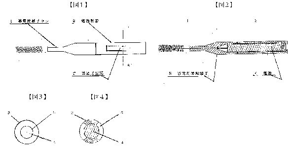
[0005]
[Action] The present invention, since the structure described above, when using this, by having a battery container, is energized contacts from a conductive space of the battery container to the anode of the battery, the conductive shaft brush cathode (-), saliva electrolyte teeth anode (+), of the electrolytic circuit is formed.
[0006]
EXAMPLES In the practice of this invention, the plaque that adheres to the teeth (+), is ionized by the electrolysis, the conductive brush axis cathode - is adsorbed in ().
[0007]
EFFECT OF THE INVENTION Therefore, since toothpick is brush-like, ease of cleaning, removal of plaque is easily done by electrolysis, prevention of plaque, prevention of bad breath, enough effect to put the teeth of the health But it is exhibited.
IT1251515
Equipment for the electrolytic sterilisation of infected root canals
Equipment for the electrolytic sterilisation of infected root canals
Sterilisation of root canals and thus cure of dental and periodontal diseases is achieved through electrolysis of the physiological solution obtained with the electrical field in a tooth.

GB1432550
DENTAL APPARATUS
DENTAL APPARATUS
An apparatus, suitable for forming a liquid in situ for the treatment of teeth for removal of caries and plaque, prevention of calculus and for brightening of teeth, comprises a reservoir means 2 for a liquid mixture which will form the treating compound when subjected to electrolysis, a pump 6, e.g. a pulse generator with suitable drive, for supplying the liquid mixture to an electrolytic cell 8, flexible hose or tubing 10 and nozzle 14, which may be a hypodermic needle, for applying the treating liquid to the teeth. The stream of liquid is preferably a pulsating stream. The treating liquid is advantageously formed from an amino compound and a chloride, bromide or iodide of an alkali or alkaline earth metal.
The present invention relates to dental apparatus, and more particularly to apparatus for application of treating liquids to the teeth.
It is known to apply to the teeth liquids which are useful in treating the teeth, e.g. for removal of caries and plaque, and prevention of calculus, and for brightening the teeth.
A class of compounds which are useful for this purpose comprises N-haloamines containing a hydroxy group, a sulfonic group, an N-acetyl group, or a carboxylic acid group. Many of these N-halomines which are most useful for such purposes are relatively unstable, and must be prepared in sitte.
It is the object of the present invention to provide apparatus for application of treating liquid to the teeth and which is adapted to permit the preparation of treating compounds immediately prior to use.
According to the present invention apparatus, for forming a treating liquid in sifg and applying it to the teeth, comprises, in combination, reservoir means for a liquid mixture which will form the treating compound when subjected to electrolysis, an electrolytic cell having an inlet and an outlet, a pump communicating with said reservoir and with the inlet of said cell for passing liquid under pressure from said reservoir to said cell, means for initiating and stopping operation of said pump, piping of which at least part is flexible having one end communicating with the outlet of the electrolytic cell, and a nozzle communicating with the other end of said piping.
For the formation of a suitable N-haloamine, a solution of an alkali metal or an alkaline earth metal halide may be decomposed electrolytically so as to provide free halogen which then reacts to form hypohalide in the presence of hydroxide ion. In order to form an N-halo derivative, the starting solution should also contain a suitable amino compound or compounds. The hypohalite reacts to form an N-halo derivative as soon as it is formed in the solution.
The starting solution may contain one or more alkali metal or alkaline earth metal halides MX and/or M2X2, where M is Li, Na, K, Rb, Cs and M2 is Ca, Sr, Ba and X is Cl, Br, I. These solutions are electrolytically decomposed according to the following equations:
Anode M++e+H2OMOH+ 1/2H2
Cathode X~il/2X2+e or
Anode M++ +2e+ 2H2OM2(OH2)+ H2
Cathode 2X-X2 +2e
The free halogen obtained immediately forms hypohalite.
2M0H +X2MOX + MX +H20
M2(0H)2+X2XM2X(OX)+H20
2M2(0H), + 2X2M2(OX) + M2X + 2H20
These hypohalites can then reaction with a suitable amino compound(s) to give the N-halo derivatives(s).


Examples of suitable starting halides are sodium chloride, sodium bromide, sodium iodide, lithium chloride, lithium bromide, lithium iodide, potassium chloride, potassum bromide, potassium iodide, rubidium or caesium chloride, calcium chloride, calcium bromide, calcium iodide, strontium chloride, strontium bromide, strontium iodide, barium chloride, barium bromide and barium iodide.
The solution formed should have an alkaline pH usually 8 to 12 and preferably 10.5 to 11.5, most preferably 11 to 11.5. Desirably the electrolysis is carried out to form a solution 0.004 to 0.016 molar in N-haloamine and while not essential, it is preferable to have present excess unhalogenated amine, i.e. in an amount up to 15 times the halogenated amine and preferably 6 to 8 times the N-halogenated amine on a molar basis.
As the amino nitrogen compounds there can be used either inorganic compounds such as sulfamic acid or organic compounds containing 2 to 11 carbon atoms e.g.
glycine, sarcosine, alpha-aminoisobutyric acid, taurine, 2-aminoethanol, N-acetylglycine, alanine, beta-alanine, serine, phenyl alanine, norvaline, leucine, isoleucine proline, hydroxyproline, omega aminoundecanoic acid, aspartic acid, glutamic acid, glutamine, asparagine, valine, tyrosin, threonine, cysteine, cystine, methionine, glutamine, tryptophane, histidine, arginine, lysine, alpha-aminobutyric acid, gamma-aminobutyric acid, alpha, epsilon-diamino pimelic acid, ornithine, hydroxylysine, anthranilic acid, p-aminohenzoic acid, sulfanilic acid, orthanilic acid, phenyl sulfamic acid, amino propanesuifonic acid, 2-aminoethanol, 2-aminopropanol, diethanolamine, ethylenediamine tetraacetic acid (EDTA), nitrotriacetic acid and aminomethanesulfonic acid.
Examples of N-halo compounds include N-chloroglycine, N-bromoglycine, Niodoglycine, N-chlorosarcosine, N-bromo-sarcosine, N-iodosarcosine, N-chloro alpha amino isobutyric add, N-chlorotaurine, N-bromotaurine, N-iodotaurine, N-chloro ethanolamine, N-chloro-N-acetyl glycine, N-bromo-ethanol amine, N-iodoethanolamine, N-iodo-N-acetyl glycine, N-bromo N-acetyl glycine, N-chloroalanine, Nchloro beta alanine, N-bromo beta alanine, N-chloroserine, N-bromoserine, N-iodosenine, N-chloro-N-phenylalanine, Nchloroisoleucine, N-chloronorvaline, N-chloroleucine, N-bromoleucine, N-iodo-leucine, N-chloroproline, N-bromoproline, N-iodoproline, N-chlorohydroxyproline, N-chioroomega-aminoundecanoic acid, N-chloroaspartic acid, N-bromoaspartic add, N-chloroglutamic acid, N-iodoglutamic acid, Nchlorovaline, N-chlorotyrosine, N-bromotyrosine, N-iodotyrosine, N-chlorothreonine, N-chlorocysteine, N-chlorocystine, N-chloromethionine, N-bromo-methionine, N chiorotryptophane, N-chlorohistidine, N-chloroarglnine, N-chloroglutamine, N-bromoglutamine, N-chlorolysine, N-chloro gamma-aminobutyric acid, N-chloro alphaepsilon diaminopimelic acid, N-chloro ornithine, N-chloro hydroxylysine, N-chloroanthranilic acid, N-chloro p-aminohenzoic acid, N-chlorosulfamic acid, N-chloro phenylsulfamic acid, N-chloro aminopropanesulfonic acid, N-aminomethanesulfonic acid, N-chloropropanolamine, N-chlorodiethanolamine, N-chloro ethylene diamine tetraacetic acid (in this compound the nitrogen atom apparently functions as a quatemary nitrogen).
Hypohalites MOX and/or M2X(OX) and/or M2(OX)D and/or N-halo derivatives specified above, can be generated in the stream of an aqueous solution, e.g. to be delivered as a liquid jet stream.
The electrolysis step is carried out in a flow system upstream of means adapted to direct the stream of activated solution onto an affected area such as the teeth. By way of Example, the cell may be coupled to a dispenser nozzle, either at the nozzle itself or in a separate location and coupled to the nozzle through piping such las flexible hose.
The stream of liquid may be at constant pressure, but preferably it is used as a pulsating stream so as to act on affected tooth material not only by abrasion caused by the stream flow, but also by erosion caused by mechanical fatiguing of the affected material by the pulsating jet.
The invention will be understood best in connection with the drawing wherein the single figure is a diagrammatic illustration of an apparatus for carrying out the invention.
Referring more specifically to the drawing there is provided a reservoir 2 for starting aqueous solution containing, for example, sodium chlorine and glycine (as well as hydroxide, e.g. NaOH to control the pH). The solution then goes vs a suction check valve 4 to a pump 6, e.g., a pulse generator with a suitable drive. The solution then goes to an electrolytic cell 8 whenever needed. Flow of the solution is controlled by a foot switch 16 in the current supply to the pump. The hypohalite, e.g. sodium hypochorite is formed in situ in the cell 8 and immediately forms the Nhalo compound, e.g. N-chloro-glycine, the cell has an inlet 20 and an outlet 22. After leaving the outlet 22 the N-halomine formed goes via a flexible hose or tubing 10 to a hypodermic needle or other nozzle 14 which can be held by a handle 12 and the flow of solution directed to a patient's mouth.
The starting solution advantageously contains (i) MX and MOH or M2(OH) and/or M2X2 and M2(OH)2 or MOH and (ii) a suitable water solution amino com pound, capable of forming an N-halo derivative by reacting with the hypohalite. Illustrative hydroxides are sodium hydroxide potassium hydroxide, calcium hydroxide, barium hydroxide.
The pump 6 may generate, for example, a steady pressure of 10 to 200 psi, preferably 20-40 psi, or a pulsating flow in which the liquid pressure varies from 0 to between 10 psi and 200 psi inclusive, during each pulse. Pulse frequency may conveniently be from 100 to 1500 inclusive per minute, and preferably 40750 pulses a minute.
The electrolytic cell must contain an anode, preferably of a graphite and cathode, preferably of stainless steel. The anode is connected to the plus pole and the cathode to the minus pole of an electric current source (not shown), for instance, a battery.
Potential between the anode and cathode may conveniently be between 2.0 and 5.0 volts.
A thermostatically controlled heating means is preferably employed, e.g., a low volume/high surface heater or a direct electric current heater, in the liquid flow circuit to allow maintenance of a temperature preferably between 35 and 45"C, and especially at body temperature 37"C in the solution projected from the nozzle.
The flexible hose or pipe is preferably capable of free bending and able to with stand pressures up to 200 psi at a maximum temperature of, e.g., 4S"C. It could cay a nozzle of a gauge of, say, 19 to 30, and preferably 20 to 23. It is useful to have an exchangeable nozzle, such as a hypodermic needle. By way of example, in the preparation of a decayed tooth for filling, any of the solutions below may be delivered through the above-described apparatus, either as a steady jet or as a pulsating jet stream, to remove caries or plaque from teeth. Steady stream conditions are less efficient than pulsating conditions.
Solution (moles in a litre of a water solution)
A NaCI NaOH Amino Compound
0.10 0.08 0.05 glycine
B KCl KOH
0.15 0.08 0.05 taurine
C LiBr LiOH
0.15 0.08 0.05 glycine
D NaI NaOH
0.10 0.12 0.10 sulfamic acid
E Cacti, NaOH
0.10 0.07 0.05 glycine
F NaCl NaOH
0.10 0.08 0.025 glycine
'0.025 taurine
EXPERIMENT RESULTS
Caries Removal - Steady Stream
Time for
Temp. Needle Pressure Potential Volume complete
Solution ( C) Gauge (psi) (Volts) (mi) Removal (min).
A 37 20 20 2.5 250 3.0
B 28 21 30 3.0 300 4.5
C 37 20 20 5.0 280 6.0
D 35 23 60 4.0 350 7.0
E 40 19 10 5.0 650 6.0
F 39 23 100 4.5 545 5.5
C 45 20 40 6.0 440 5.0
Caries Removal - Pulsating Stream
Time for
Temp. Needle Pressure Potential Volume complete
Solution ( C) Gauge (psi) (Volts) (ml) Removal (min).
A 37 20 0-10 4.0 285 3.0
B 37 20 0-40 3.5 230 2.0
C 35 20 0-40 4.5 440 3.5
D 40 21 0-25 4.0 350 4.0
E 38 23 0-100 5.5 380 5.0
F 38 20 0-80 5.0 400 4.5
A 39 20 0-200 6.5 505 3.5
D 38 20 0-60 4.0 715 6.0
WO9300864
METHOD AND DEVICE FOR TREATING DENTAL OR OSTEOARTICULAR SURFACES
METHOD AND DEVICE FOR TREATING DENTAL OR OSTEOARTICULAR SURFACES
A method for treating dental or osteoarticular surfaces, involves applying to said surfaces, by means of two electrodes, an electric field located in an electrolytic medium on a solid or gelled support. A device for implementing the method is also provided.
DESCRIPTION
"Treatment method for tooth surfaces or osteo've ± iculaires, devices for its implementation."
The present invention relates to a method for treating tooth surfaces or osteo-articulaires.
It is also capable of causing the disappearance of discolored tooth.
A tooth surface treatment processes include, firstly cleaning techniques, scaling and bleaching, the other of the surface preparation techniques] enamel, dentin and cementum to e.g. bonding bio-materials such as adhesives type materials dentin-enamel and composite resins.
In periodontal surgery, to favor a "reattachment" collagen fibers on a cementum surface, one must remove the surface of any residual tissue and necrotic cells.
In the field of surface preparation techniques of the enamel and dentin for bonding bio-materials, changes in dentistry over the past twenty years has re- duce the use of size cavities with rotary instruments before placing metal restorations: inlay or silver amalgam.
Dentistry limited to the eviction of pathological tissues, preparation of tissues by gluing products and the introduction of composite resins has gradually imposed.
At one stage of the bonding, the enamel is currently treated with orthophosphoric acid at 37% presented in the form of a colored gel or acid solutions.
The resulting acid etchants and acid balances the same need to be systematically removed.
This is usually done using a water jet.
However, these methods are uncertain and uncontrolled and have failed so far to obtain statements of suitable surfaces root planing.
Similar problems also arise in the field of collages in bone and joint surfaces.
Extrinsic staining of the teeth are usually due to the deposition of secondary mineralized plaque.
Chromogenic bacteria are the cause of discoloration associated or not with for- mation of tartar, the latter being colored by the tobacco tar, caffeine, etc.
The tooth cleaning processes are designed to remove these stains and deposits by methods either mechanical or chemical.
In recent years, new tooth whitening techniques have come onto the market, which carry first alteration, either of the organic matrix, or the mineral structure and the diffusion through the enamel of hydrogen peroxide, which acts on intrinsic pigments of the tooth.
All existing methods assume the pose of a complex surgical field to avoid chemical burns of the mucosa.
It would therefore be desirable to have techniques for local applications, limited in space and does not require lengthy maneuvers (and random) isolation when they are implemented remotely necks of the teeth.
The present invention aims to propose a method of treatment of dental surfaces and osteoarticular that overcomes the drawbacks of the techniques of the prior art.
The invention thus provides a method for treating tooth surfaces and bone articulai- res, characterized in that there is applied to the surface to be treated, by means of two electrodes, a localized electric field, in an electrolytic medium solid or gelled medium.
According to a first embodiment, the solid support is in the form of a buffer consisting advantageously of a material selected from cotton, fiber or paper impregnated.
According to a second embodiment, the support and the electrolytic medium form a gel chosen advantageously among agar, a polysila- not, pectin and a polyester.
The conductivity in the electrolytic medium that can be provided by a neutral salt, preferably selected from KN03, NaCl and KC1 in an aqueous medium when the operating time is greater than about 2 minutes.
It is ensured more advantageously by a basic salt, dilute aqueous solution of alkali hydroxide, preferably selected from KOH, NaOH and LiOH or a weak acid when the duration of intervention must be less than 2 minutes, or when the is desired a more powerful action on the surface.
Advantageously, the electric field is radial.
Preferably is applied between the two electrodes a voltage of between 2 and 5 V and an intensity comprised between 5 and 100 mA.
The inventive method of treatment of dental surfaces or osteoarticular is advantageously used for cleaning dental or bone surfaces.
It provides micro-reliefs preparing tooth surfaces for bonding biomaterials and bone and joint surfaces for bonding biomaterials in bone and joint treatments.
The invention also relates to a device for carrying out the method consisting in: a first electrode surrounded by an inner tube made of insulating material; - A support consisting of a solid pad of a material selected from paper, cotton, fiber, impregnated by an aqueous medium in salt or a gel electrolyte-containing partially disposed in the inner tube so that the one end of the solid support or gel comes into contact with the first electrode within the inner tube and the other end protrudes from the inner tube; a second electrode disposed outside of the inner tube and s' winding partly onto the end thereof, so as to come into contact with the solid or gelled carrier; the assembly formed by the inner tube, the electrodes and the solid or gelled carrier being placed in an outer tube made of insulating material, so that the end of the solid or gelled carrier protrudes from the end of the outer tube, the two electrodes being indifferently to the cathode, the other one anode.
In a first embodiment according to the invention, the inner tube consists of a tube type "pencil", the first electrode preferably consisting of a watertight metallic wire, in particular nickel, stainless steel or precious metal or in a mine atoms whose diameter is advantageously between 1 and 5 millimeters.
In a second embodiment according to the invention, the inner tube is a syringe that contains the conductive gel and permits the expulsion as needed.
In the case where the operating time is greater than about 2 minutes and / or the desired depth of micro-reliefs is less than about 5 microns, the buffer preferably consists of cotton or paper impregnated with KNO ^ in aqueous medium and the gel agar-agar, optionally supplemented with a filler such as graphite and preferably containing the aqueous medium in N0_ powder.
In the case where the operating time is less than about 2 minutes and / or when the desired depth of the micro-reliefs is between about 5 and about 10 microns, the buffer is preferably made of cotton or paper, the gel being from 1 agar-agar and 1 electrolyte is chosen either from a weak acid such as <H> -? <P0> 4 <or> CH, COOH in aqueous media, either from an alkali salt in aqueous KOH and diluted medium.
To a voltage of 5 V and a duration of inter- vention 2 minutes, for example, use
H3P04 or CH-COOH 1N electrical current are respectively 40 and 8 m or 0.1 N KOH, the electrical current is 10 mA.
In an alternative embodiment of the device according to the invention, the first electrode is retractable.
The invention will be explained in more detail in the case of the treatment of tooth surfaces with the accompanying drawings in which: Figure 1 shows a device of the type "mechanical pencil" according to the first embodiment of the device according to the invention; Figure 2 shows a device of the type "syringe" according to the second embodiment of the invention.
Figure 1, shows a device of the "mechanical pencil" for the process of implementation of the invention.
On the tooth surface 1 to be treated, is applied to the <'> hand end 2 of the device consisting of an insulating material in the inner tube 3 through which a first electrode 4 formed of a material such as nickel or graphite , a buffer 5 partially inserted in the inner tube 3 so that the one end 6 comes into contact with the first electrode 4 and the other end 7 than the inner tube 3.
The buffer is advantageously constituted by a cotton impregnated KNO- in aqueous medium to ensure the electrical conductivity with a second electrode 8 made of a material such as nickel or graphite, disposed outside of the inner tube 3 and s' partially winding on the end 9 thereof and the 5 buffer contacting the dental surface to be treated.
Advantageously, there is inside the tube 1 March minithermocouple 10 so that one end thereof is located at the buffer 5, the other end being connected to a circuit breaker device not shown in the figure thereby allowing control of the buffer temperature.
For the treatment of dental surfaces, the treatment temperature is set preferably at 37 <*> C, and does not exceed 45 <*> C to the tooth surface.
The set of elements described above is placed in an external tube 11 in materieu insulator so that the end 7 of the buffer 5 exceeds one end of the outer tube 11.
Advantageously, the electrode 4 is retractable to allow the removal and replacement of the buffer 5.
Advantageously, the electrode 4 bit also be brought into contact with the projection surface to be treated, the electrode 8 remains in a stationary position in contact with the swab so as to make a per-spot treatment of the surface to be treated .
The two electrodes are either the anode and cathode.
They are connected to the negative pole and the other to the positive pole of a current source.
When applied between the two electrodes a current of a voltage of between 2 and 5 V and an intensity comprised between 5 and 100 mA, it is established in the electrolytic medium, consistué by the buffer, a local electric field between the two electrodes as a result of which a product separation and migration of the impurities attached to the tooth surface when the device is used for purposes of clea- ning and bleaching or corrosion producing micro-reliefs that allow bonding subsequent biomaterial when the device is used for this purpose.
Figure 2 shows a second embodiment of the device according to the invention wherein the inner tube comprises a syringe 3 with a plunger 12 through which a first electrode 4 whose one end is connected to one of a pole a power source not shown in the Figure, the other end being located within the tapered end 13 of the syringe 3.
The electrolytic medium contained within the syringe 3 is constituted by a 5 gel advantageously consisting agar, laden with a neutral salt such as KNO- ,.
When the piston is actuated, a drop of gel is formed outside of the tapered end 13 of the syringe 3 and comes into contact with the loop formed by a second electrode 6 arranged as above to the outside of the syringe 3 and wound on the end thereof opposite the piston.
The device shown in the embodiment of Figure 2 operates in the same manner as described above.
Tests were conducted on samples of human teeth.
Appraised results in a scanning electron microscope show that the electric current used by these methods have a specific action on the tooth surfaces, whether it be enamel, dentine or cementum.
This action modulated through flexible electrical parameters can be used in vivo for cleaning, superficial or deep laundering and microreliefs achievement to prepare surfaces for bonding dental biomaterials by formation on an area being smaller than the diameter of the smaller electrode, or about 1 to 3 millimeters, micro-reliefs in the form of micro-wells of micron or sub-micron diameter, the assigned depth can be controlled by adjusting the parameters of electrochemical treatment.
Compared with current techniques of cleaning dental surfaces by thermo-chemical route, the benefits of the invention are periods of intervention shorter, an absence of problems of dripping or confinement by banks through the use of gels or porous or fibrous materials instead of liquids, a job in a work area well eir- conscripted may be very small, and. great, job security through currents and low electrical potentials.
Compared to known methods mechanically or chemical surface preparation for bonding acid bio-materials, the invention allows easier control by adjusting the working parameters.
It provides micro-reliefs on the tooth surface quite conducive to bonding biomaterials, and suggests the prospects for therapeutic collages in elderly patients with caries collar.
Tests conducted on the compact and spongy bone have shown that the invention allowed the process to eliminate the materials located between the lamellae of Haversian systems.
On the cancellous bone, the method of the invention allows to eliminate the residues endostées cavities and create micro-features on the spans.
Prospects in the field of collages in the musculoskeletal therapeutic are therefore also possible.
CN1054188
ELECTRONIC METHOD AND IMPLEMENT FOR CLEANING TEETH
ELECTRONIC METHOD AND IMPLEMENT FOR CLEANING TEETH
Teeth or artificial teeth are put in water or saliva in which positive and negative stainless steel electrodes are arranged. Two electrodes are connected to a DC power supply for electrolytic cleaning. The dental protein deposit bearing positive charge is separated from the teeth. The mucosa of dental deposit is dissolved in water. The calcium in odontolith of calcium lactate is educed out from negative electrode. Thus, the teeth or artificial teeth are cleaned safely and effectively and the dental periphery is cleaned in large area. The implement includes periodontal cleaner, artificial teeth cleaner, etc.
DESCRIPTION
[0001]
The present invention relates to a method for cleaning teeth and electronic appliances, belong to the medical field.
[0002]
As we all know, bad breath, dental caries, pulpitis, periodontal abscess for people to common diseases.
Tartar is a common reason for their formation.
The mouth of the mouth of a large number of bacteria remaining food is broken down into lactic acid, lactic acid dissolves the tooth enamel and the main component of calcium and formation of dental caries, the cavities.
Also acid will combine with saliva to form plaque calcium.
Will stimulate the gums caused by plaque and gum abscess, periodontitis, if further dissolve tooth bone, then slowly form pulpitis, alveolar pyorrhea.
Usually people use ordinary toothbrush and toothpaste to clean, but the brush can not afford to fifty percent of the total tartar.
Tartar on teeth is to put teeth into the water soaked or washed clean, but the cleaning effect is not ideal.
Doctors periodontal cleaning, use beat, Knife and other methods of pain the patient to remove tartar, calculus, both patient suffering, but also prone to infection.
[0003]
Object of the present invention is to achieve an electronic method and apparatus of cleaning teeth, tooth cleaning electronic appliance composed of positive and negative electrodes, by electrolytic methods clean the teeth and dentures, periodontal clean, safe and effective removal of plaque mucosa, clean-up of tartar, plaque eliminate electrolysis.
[0004]
An electronic method of cleaning teeth proposed by the invention is such.
The teeth or dentures in a mixture of three types of liquid water, saliva, water and saliva of any one of liquid, and the liquid was put into use in both positive and negative electrodes made of stainless steel, the two positive and negative electrodes connected to the DC power, at a current strength of 300 mA -10 microamperes conditions electrolytic cleaning.
[0005]
Such electronic method of cleaning teeth present proposed invention is based on the principle of implementation.
Tartar on the teeth or dentures usually contain large amounts of protein, when the teeth or dentures placed in the water, saliva electrolyte, the teeth or dentures with respect to the negative electrode is positively charged, containing a positive charge on the teeth or dentures protein tartar from teeth or dentures will, tartar mucous membranes dissolved in water.
Additionally, calculus in water or saliva will be completely dissolved in the electrolyte, on the negative electrode was isolated calcium.
The calcium tooth enamel and tooth itself is insoluble in water or saliva electrolyte.
Precipitation of calcium ions on the negative electrode only in calcium lactate, calcium in that calculus.
Thus the use of the present invention proposed a method of cleaning teeth which electronic, can safely and effectively clean the teeth and dentures, and efficiently, cleaning periodontal large area, reducing the patient's pain.
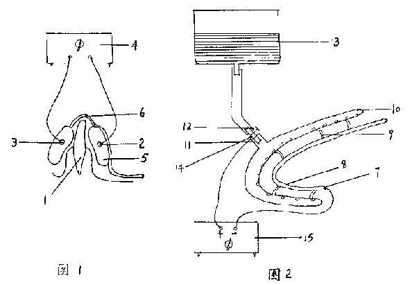


[0006]
Electronic cleaning teeth proposed method according to the invention, the appliance should be like this: DC power supplies, and DC power supply for electrolysis phase and made of stainless steel both positive and negative electrodes, and carrier components.
[0007]
DC power supply may be a battery or may be ac rectifier.
This electronic use as cleaning teeth having periodontal cleaner, its DC power supply should be adjustable DC power, adjust its current intensity in the range of 300 microamperes -3 mA.
Thus according to the specific patient periodontal disease, adjusted for cleaning.
When used as an electronic toothbrush to clean, which current intensity is controlled within the range of 300 microamperes -3 milliamps.
When used as a denture cleaner, because it is off to clean the teeth, it may be appropriate to larger current density range, the current intensity in the range of 300 microamperes -10 mA.
[0008]
Positive and negative electrodes made of stainless steel, as chromium stainless steel, or chrome-nickel stainless steel.
[0009]
Positive and negative electrodes may vary according to the shape of the electronic apparatus to be used to clean teeth and fixed, such as periodontal cleaner electrode, some to be placed in the oral cavity, the shape thereof is shaped articulate arc shape, in order to avoid direct contact with the teeth, use has sucked seepage around the electrode isolation wrap packaging, the material may be non-toxic foam, cotton or filter paper.
[0010]
Vector is used for loading or support the electrode and the power supply, according to the electronic appliance as a periodontal cleaning teeth cleaning, denture cleaning, electronic cleaning toothbrush specific situation, the carrier may be a stent, covered containers, toothbrushes.
[0011]
The following examples still further illustrate the accompanying drawings.
[0012]
Figure 1 is a medical periodontal disposable cleaner.
[0013]
Figure 2 is a medical periodontal cleaner reusable.
[0014]
Figure 3 is denture cleaner (?).
[0015]
Figure 4 for denture cleaner (?).
[0016]
Figure 5 is an electronic toothbrush clean.
[0017]
Example 1.
[0018]
This is a disposable medical periodontal cleaner use.
Be seen from Figure 1, the inner and outer sides of the teeth of the tooth 1 has positive and negative electrodes 2 and 3, the positive and negative electrodes through the wires and an adjustable DC power supply 4 in contact.
Both positive and negative electrodes are articulate shaped circular arc shape, and is isolated with suction water permeability wrap packaging 5; carrier 6 is bridge-shaped bracket, both ends of which are connected to the bridge of the two electrodes of the packaging.
[0019]
In use, the positive and negative electrodes and packaging in ?????, then placed in the oral cavity, positive and negative electrodes sandwiching the teeth, after power generating electrolysis, absorption of calcium lactate calculus on the negative electrode, to remove tartar mucosa, cleaning tartar, electrolysis remove tartar, which cleared the periodontal.
[0020]
Example 2.
[0021]
This is a medical periodontal cleaner reusable.
2 seen from the drawings, the negative electrode 7 is articulate shaped circular arc shape, and is isolated with suction water permeability 8 wrap packaging.
Vector is a bridge-shaped support 9, both ends of the bridge in which one end of said negative electrode packaging phase, and the other end connected to articulate shaped arcuate outer teeth 10 seepage.
Teeth seepage is a hollow tube, a number of water seepage holes on the wall.
The tooth is connected with water seepage into the outer pipe 11, the inlet air-control valve 12, the other end into the water storage tank 13 connected.
The positive electrode 14 is filamentous, its end electrodes extending into said outer teeth leakage in the inlet pipe.
Can also be used for some stainless steel tube connected to the inlet pipe in the head, so that the positive electrode and filamentary stainless steel ferrule connection, the above three methods can be external teeth entering the water seepage positively charged.
Positive electrode and an adjustable DC power supply 15 in contact.
[0022]
In use, a negative electrode on the back side of the teeth, the teeth on the outer side of the outer water seepage control teeth.
Power open the control valve, the water flows through the positive electrode, so with a positive charge outside the seepage of water through the filter penetrate the tooth in the mouth, and teeth with a positive charge, so the tartar off the teeth, tartar electrolysis, calcium lactate in fold out from the negative electrode, periodontal been cleaned.
[0023]
Proposed by the present invention are two medical periodontal cleaning, changing doctors use beat, Knife and other traditional methods of pain the patient, so that hidden in the inside of the gingival calculus on the gum without ripping on gums clean energy, greatly reducing the patient's pain.
Both medical periodontal cleaning for easy operation, palate-shaped bracket can be installed under the bridge-shaped bracket, in the cleaning operation, the palate-shaped tokamak in the gums, easy fixed electrode, and easy to operate.
[0024]
Example 3.
[0025]
This is a denture cleaner.
Seen from FIG. 3 is a container with a lid carrier 16, the DC power supply 17 is mounted on the cover, both positive and negative electrodes 18 and 19 are filamentous and extending into the container, the container lid can be plastic or glass and other materials made.
[0026]
Example 4.
[0027]
This is a denture cleaner.
Figure 4 shows that the carrier 20 is a stainless steel container lid and the container as a positive electrode, 21 is connected by wire to the DC power supply, DC power supply unit on the cover, the negative electrode 22 is filiform, and extending into said container.
[0028]
Both denture cleaner when in use, first loaded in the container with water, then with aqueous electrolyte dentures placed in the positive and negative electrodes, dentures with respect to the negative electrode is positively charged.
Contains a positively charged protein tartar on teeth from dentures, tartar mucosal dissolved in water, the calcium lactate is isolated, attached to the negative electrode.
Such dentures got cleaned.
So with a toothbrush without toothpaste to brush teeth, and without medication water to soak the dentures, the dentures every night as long as there is water injection into the denture cleaner, and to clean dentures, removing tartar both clean, and very convenient.
[0029]
Example 5.
[0030]
This is an electronic toothbrush clean carrier using a toothbrush 23, the DC power supply 24 is mounted on the handle, both positive and negative electrodes of filamentous, the positive electrode 25 lying in front of the waterline trench toothbrush 26 years.
Water trough can start in the back or side of the toothbrush, the purpose of preventing the roots in direct contact with the oral electrode, a negative electrode 27 disposed at the bristles.
When brushing simply by water or saliva so that the mouth and teeth with a positive charge, a positively charged protein tartar from the teeth off, dissolved in a mixed electrolyte tartar mucosa in water and saliva, as well as calculus on the teeth is electrolyzed and soluble in the electrolyte and precipitated on the negative electrode from calcium.
This electronic toothbrush to clean without the use of toothpaste and drugs, will be able to clean the teeth, eliminate plaque and calculus, ordinary toothbrush cleaner than clean thoroughly.
If a replaceable battery, and can replace the brush head, can improve efficiency.
[0031]
In summary, the present invention proposed a method of cleaning teeth and electronic appliances, fundamentally changed the clean teeth, dentures, periodontal cleaning and traditional methods.
Clean teeth cleaning dentures, remove tartar and plaque both clean and thorough, and very convenient.
When the treatment of periodontal disease, the patient no sense of pain, but also easy to infection.
As a result of low-voltage DC power supply, safe and reliable to use.
Electronic cleaning dental appliance has a simple structure, easy processing, easy to use, low cost, and this electronic cleaner has a vast market, both family dental hygienist essential commodities, but also a hospital for treatment of essential medical supplies clean teeth .