Divining
/ Dowsing Rod Patents
RO127928
HUMAN BODY DETOXIFICATION METHOD NAMED VIP
YU45840
Divining Rod Transformer
GB2159856
Divining rod
GB683173
Apparatus for influencing divining rod reactions and a method of using same
GB147186
Improvements in or relating to apparatus of the divining rod type
GB146840
Improvements in apparatus of the divining-rod type for detecting the presence of subterranean substances and for like purposes
GB147052
Improvements in apparatus of the divining-rod type for detecting the presence of subterranean substances and for like purposes
GB879568
Appliances for detecting the presence of water, metals and other materials
FR2580821
Novel type of detection apparatus
FR2446081
Divining rod with inset pearl - has central spiral and two branches which are joined to form setting for precious stone
DE202005015433
Divining rod for therapeutic applications…
DE19517828
Deflection measuring device for divining rod
DE4423279
Divining-rod for detecting geobiological stimuli
DE4341366
Test instrument for divining
DE4011344
Antenna for use as divining rod or for scientific investigation...
DE3806435
Diviner (divining rod) with sensitivity control
DE3600505
Radiation-measuring device employing the principle of a divining rod
DE3036085
ANORDNUNG ZUR ELIMINIERUNG DES DEN AUSSCHLAG DER WUENSCHELRUTE...
DE3027367
Divining rod for one-handed operation - has cylindrical brass grip holding wire with swinging object at end
DE2902338
Water detecting rod of magnetised steel wire - has forked shape with oppositely wound spirals fitted over opposing fork shank poles
DE2364935
Deflection of harmful radiations - used against e.g. gamma rays, emanating from underground water sources
US3717950
ADJUSTABLE DIVINING ROD DEVICE
DE202005000519
Tensor to be used in radionics, made of fiber glass or carbon fibers with wooden handle
DE3020636
Dowsing rod with stackable point extension tube - has hollow pyramid shaped chamber for test materials
CA792862
DEVICE FOR THE NEUTRALIZATION OF THE DOWSING-ROD RESPONSES CAUSED BY SO-CALLED TERRESTRIAL RAYS
http://worldwide.espacenet.com/advancedSearch?locale=en_EP
RO127928
HUMAN BODY DETOXIFICATION METHOD NAMED VIP
HUMAN BODY DETOXIFICATION METHOD NAMED VIP
Inventor(s): PANAITESCU VICTOR
The invention relates to a method for the detoxification of human body. According to the invention, the method consists in attaching a textile sleeve to both wrists of a person, said sleeve comprising at least four energy collectors made of an insulated stranded copper conductor having a cross section of 2.5 mm and a length determined by means of a divining rod, which release white energy, provides positive ions in the range of 3x10and develops a pH=2, the energy collectors being arranged in each sleeve in two parallel rows, at a distance of 40...50 mm, while, in the area of each ankle there is attached another textile sleeve which contains at least four energy collectors made of a conductor of monofilar copper FY having a cross section of 1.5 mm, a length determined by means of the divining rod, which emits energy on the wave length of white light and develops a negative ionization degree i()= 310 and a pH=7.5, both feet being introduced into a hot water container wherein coarse salt is dissolved, the level thereof preferably reaching the lower part of the inner malleolus.
YU45840
Divining Rod Transformer
Divining Rod Transformer
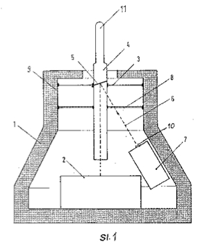
CONVERTER fluctuations that can convert mechanical vibrations into electrical oscillations, characterized in that the inner wall (9) of the cylindrical upper part of the casing (1) of pot-shaped design with its jobodom attached prose membrane (3), in which the upright mounted to the light permeable rods (4) having an upper end (11) projecting from the housing (1) and which is mounted in the plane of the membrane (3) at an angle of the reflector (5) that is parallel to the membrane (3) on the inner wall (9) the casing (1) is fastened to the outer end of which is attached to the rod (4) and that at the bottom of the casing (1) in the direction of the axial axis of the rods (4) attached to a light-sensitive sensor (2) at which the wall (9) of the housing (1 ) attached to the light source (7), whose outlet opening (10) is directed towards the reflector (5).
GB2159856
Divining rod
Divining rod
Inventor(s): KRUHLER WILLI
Also published as: DE3418425
A one-hand divining rod has a handle portion (1) to which a flexible indicator portion (2) is attached. The indicator portion is formed as a straight wire (2) at one end of which a terminal element (3) is provided, and the other end of which is connected to one end of the handle portion which is formed as a metallic tube (1). A tuning element (4) made of electrically conductive material is received in the tube (1). The tuning element (4) is in electrically conductive connection with the tube (1), fills up at least part of the cross-section thereof and is slidable in the longitudinal direction of the tube. By sliding adjustment of the tuning element (4) within the tube (1), the divining rod can be
SPECIFICATION
The invention relates to a one-hand test rod having a handle portion to which a flexible indicator portion is attached, said indicator portion being formed as a straight wire at one end of which a terminal element is arranged, and the other end of which is connected to one end of said handle portion which is formed as a metallic tube.
Such test rods which are also named dowsing rods, are known and described e.g. in DE OS 30 27 367 and DE-GM 82 24 305. They are used e.g. for tracing threads of water and mineral resources, or for carrying out other investigations, e.g. tracing so-called "irritating stripes" on the ground surface.
One-hand test rods of the aforementioned type are characterized by the fact that, with their help, investigations can also be carried out by persons having only little practice.
The problem underlying the present invention was seen in the further development df a one-hand test rod as described above and as mentioned in the preamble to claim 1 to the end that the sensibility and precision of measurements which are carried out by means of the test rod, can be considerably increased.
The aforementioned problem is solved by the features which are contained in the characterizing clause of claim 1.
Preferred embodiments of the claimed test rod are described in the subclaims.
The invention is based on the perception that, by displacing the tuning element within the tube of the handle portion, a tuning operation can be obtained which does not only increase the exactness of measurements carried out by means of the test rod to a considerable extent, but, which, in many cases, forms the only possibility for finding out certain particular spots or regions in space in which the conditions clearly distinguish from those in the environment. In such spots or regions, the indicator portion of the test rod will begin to vibrate, especially its terminal element will carry out a circular spinning motion. As can be observed, a displacement of the tuning element within the tube will increase, decrease or entirely stop the vibration.It has further turned out that, upon adjustment of the tuning element in different positions within the tube, different spots and regions in space will bring about the optimal sensibility or exactness of the measuring operation, i.e. the maximum deflection of the indicator portion.
Since the phenomena causing the deflection of such test rod have not yet been definitely cleared in a scientifically acknowledged manner, attention is directed only to the fact that the one-hand test rod according to the invention behaves as if the tube of the handle portion together with the displaceable tuning element, forms an electric resonant circuit, e.g. a cavity resonator as used in microwave techniques, in which cavity resonator a resonance condition, e.g. a standing electric wave, is built up upon adjustment of an electrically conductive tuning element in different positions. It has been found out that the test rod according to the invention provides for the possibility of obtaining a very accurate tuning to these "resonant positions", and that the results are well reproducible.
The one-hand test rod according to the invention will be further described by way of example, with reference to the accompanying drawing showing, in longitudinal section, one embodiment of the one-hand test rod.

To one end of a handle portion 1 which is formed as a cylindrical tube, an indicator portion 2 is coaxially attached, said indicator portion being formed as an elongated wire.
The tube 1 is made of electrically highly conductive material. E.g., a copper tube having a diameter of 22 mm can be used. The wire 2 can likewise be made of electrically conductive material such as brass. The front end of the tube 1 is closed by a plug 8 made of electrically non-conductive material, e.g. a plastics material. The plug 8 is provided with a central bore. The rearward end of the tube 1 is closed by a plug 7 made of electrically conductive material, e.g. brass. Both plugs 7 and 8 form also a holder for a guide element which is in the form of a bar 9. The bar 9 can be made of metal or of an electrically nonconductive material such as plastics material.
A tuning element 4 is longitudinally slideably arranged within the tube 1. The tuning element 4 is made of electrically conductive material such as copper or brass. It can be formed cylindrically, whereby the cross-section of the tube is partially filled up, and an electrically well-conductive connection with the inner wall of the tube is established through a projection 4a. The bar 9 passes through a central bore of the tuning element 4 so that the latter can slide along the bar 9 within the tube. In the outer surface of the tube 1 an elongated slot 1a is provided, said slot extending over part of the length of the tube and ending near the two ends thereof. A stud or bolt 5 passes through the slot 1 a which stud is screwed into the tuning element 4. A knob 6 is secured to the outer end of the stud 5 for manual actuation.
The terminal element which is attached to the free end of the wire 2, is formed as a conical wire helix 3 whereby the wire can be made of the same material as the wire 2. The tip 3a of the conical wire helix is firmly connected to the tip 2a of the straight wire, and the wire helix 3 is arranged in such a way that its base 3b faces towards the handle portion.
On the outer surface of the tube 1, a measuring scale (not shown can be provided by means of which the relative position of tuning element 4 within the tube can be read off. Further, in a manner not shown, the actuating element can be provided with a catch member by means of which the tuning element 4 can be locked in a certain position.
This catch member can e.g. be formed so that the stud 5 is adapted to be screwed into the tuning member 4 to such an extent that the actuating knob 6 rests on the outer wall of the tube thereby forming a catch member. Further, a spring element (not shown) can be provided against the force of which the tuning element 4 can be slideably adjusted.
The above described one-hand test rod is operated as follows. The handle portion of the test rod is grasped by hand, preferably such that the thumb of the hand rests on the actuating knob 6. The indicator portion, with its forward end, is moved towards the spot or region in space which is to be investigated.
Simultaneously, through the knob 6, the tuning element 4 is displaced until a deflection is observed to the end that, e.g., the terminal element carries out a circular movement. By moving the tuning element 4 forth and back, it is easy to adjust the most sensitive position of the measurement, namely the greatest deflection at the forward end of the indicator portion. The corresponding position of the tuning element 4 can be read from a measuring scale which may be provided adjacent to the elongated slot la of the tube 1. By means of the tuning element in a fixed or, possibly, locked position, it is easy to carry out further measurements by searching for spots or regions in space in which a deflection of the indicator portion occurs when the test rod has been tuned in this way.
In practical tests it has been found out that different but reproducible positions of the tuning element 4 can be associated with different spots or regions in space which may also be influenced by the presence of persons, animals or plants. In this case, too, the test rod according to the invention behaves in a manner as if phenomena were observed to which differing resonance conditions or, in connection with a cavity resonator, differing natural frequencies or natural wave lengths, respectively, can be associated.
GB683173
Apparatus for influencing divining rod reactions and a method of using same
Apparatus for influencing divining rod reactions and a method of using same
Inventor(s): JOHANNES GEORGE MIEREMET
Apparatus for influencing or suppressing the forces giving rise to divining rod reactions is itself provided with a wire screening means, thereby extending its area of effectiveness. The apparatus for influencing the rod reactions comprises a wooden box in which metal plates and wires are disposed in a particular manner. This box is placed at the mid-point of two perpendicularly crossed pairs of parallel wooden supports which also carry a continuous wire ring, the centre of which coincides with the mid-point of the box. In a larger type of equipment the main components are placed in a concrete pit below ground level and the shielding ring is placed outside the pit.
COMPLETE SPECIFICATION
This invention relates to apparatus for influencing forces which give rise to divining rod reactions, and to a method of influencing such forces.
Experiments show that the location of water, ore and oil layers, pipe lines, electric cables, and similar objects in the ground may be determined by means of a divining rod handled by a susceptible person.
Moreover, forces giving rise to divining rod reactions occur above sharply defined tracks on the earth surface, such that a deflection of the divining rod is always observed above and does not occur outside the same, although the presence of these tracks can be sensed by the diviner at a distance. For the sake of simplicity, the force or influence concentrated in these tracks, and causing deflection of the divining rod, is known by diviners as (( earth-rays."
The physical nature of such " earth rays " has not yet been established. In particular, it is not certain whether a radiation in a physical sense actually occurs, although it has been assumed that the influence is due to reflection of cosmic radiation by certain parts of the earth surface. In certain cases, it has been possible to check the course of the tracks by the divining rod with the aid of physical apparatus, such as the Geiger-Muller-counter. In experiments, wherein a diviner was connected with a cardiagraph, distinct variations of the cardiagram have been observed upon passing the said tracks.
As for scientific literature on this subject, attention may be directed, for instance, to the book by J. Cecil Maby and T. Bedford Franklin: " The Physics of the Divining Rod " (1939).
Hereinafter, the physical nature of the earth-rays " will will be left out of consideration. The term " earth-rays " will only be used as naming the forces which bring about a deflection of the divining rod above certain tracks on the earth surface, the nature of these forces being unknown, although their existence cannot be denied.
Various scientific experiments and verifiable solitary cases point to a certain correlation between the occurrence of the forces indicated as "earth-rays and the state of health of people, animals and plants, to the effect that a prolonged stay above one of these tracks would cause or enhance a disposition for certain diseases and aberrations, the degree of this disposition being dependent on the condition and the susceptibility of the exposed individual.
Hence, devices for influencing, and in particular for suppressing the forces indicated as " earth-rays " have not only a scientific value from the point of view of their use as a means of experiments, but are also valuable in the interest of public health and of the economy of agriculture and cattle-breeding. Experiments as indicated above have also been extended to the practical results of such devices and have confirmed the effect thereof.
Hitherto, various difficulties were involved in the experiments with such devices (of which a very effective species will be described hereinafter), and in the permanent installation thereof, because the effect of the device appeared to be very variable.
The present invention is based on a recognition which has been confirmed by numerous experiments, to wit that the effect of the said devices is severely interfered with, or even completely suppressed when the devices are positioned within a track in which the reactions to be suppressed occur, or when metal objects are brought into the vicinity of the devices.
Thus, a permanent supervision of the devices on the spot was necessary, in particular because the course of the earth-rays is subject to variations, so that an apparatus initially located outside such a track can come to lie within the same.
The invention has for its object to remove these disadvantages. According to the invention, the apparatus which, as explained hereinbefore, serves to obtain a screening effect and to keep a certain area free from the influence of the earth-rays, is provided in its turn with wire screen- ing means.
For this purpose it has been fbund to be particularly effective to surround the apparatus exerting the geophysical influence with a metal ring. The range within this ring, wherein the apparatus is located, is free from the influence of earth-rays, and the detrimental influence of metal objeets brought close to the apparatus is found to be removed- at the same time.
Preferably, the said ring is used in combination with a screening by means of crossed wires. If such crossed wires are arranged in a suitable manner underneath the apparatus, they act to make the effect of the apparatus independent of the influence of earth-rays, and if- used in combination with the said ring they support the action of the latter; Moreover, the crossed wires provide an additional protection for instance in- case the effect of the ring is eliminated. It has been found that such elimination of the effect of the ring m,ay be caused by grounding, and, of course, a grounding of the ring might occur involuntarily. This additional protection is also effective with respect to disturbing objects -underneath the apparatus, such as metallic waterpipes, and the like; Favourable results have been obtained with a ring made of soft copper and with crossed wires of the same material. Preferably, the copper consists of so-called annealed wire.
The exact nature of the invention, - and various additional objects thereof, will be apparent from the following description, given with reference to the accompanying drawings. In this description, an apparatus will be disclosed which is adapted to be used to advantage in combination with screening means according to the invention, and it will be shown in what manner the invention is to be performed, with respect to constructive details and to the arrangement of the various parts, in order to obtain the most favourable results.
Figure I shows by way of example a vertical cross-section of an apparatus to which the screening means according to the invention may be applied.
Figure 2 is a plan view of the apparatus shown in Figure 1, the top part of the casing being removed.
Figure 3 is a schematic plan view of a combination according to the invention, comprising an apparatus of the kind shown in Figures 1 and 2, and screening means applied to said apparatus.
Figure 4 is a part side view, and a part cross-section taken along the line IV---IV, of the combination shown in Figure 3.
Figure 5 shows an embodiment of the combination according to the invention located in a pit below. the earth surface.
Figure 6 illustrates the method accord- -ing to the invention of suppressing the action of " earth-rays " in an extensive area, such as a village or a residential quarter.


As shown in Figures 1 and 2, the apparatus to be screened is enclosed in a wooden casing 29, and comprises. two spaced juxtaposed elements 1 and 2, each consisting of two horizontal plates 11, 14 and 16, 19 respectively, lying one above the other, and of a plurality of wire-like members 15 and 20. Corresponding parts of both elements, i.e., the plates 11 and 16, the wire-like members 15 and 20, and the plates 14 and 19 lie at the same level. The plates -11-, 14,-16 and 19 are made of a material of good electrical conductivity, preferably copper, and the wire-like members are made of a precious metal, preferably silver. The plates of one of said elements, in the present case the plates 16 and 19, are provided with a continuous coating of another metal, In case copper is used for the plates, this coating consists of nickel. However, the plates may also be made of silver, and in that case the coating of the plates 16 and 19 consists of gold.
The upper plates 11, 16 of both elements are covered by lead plates 13 and 18 respectively, which serve to protect the elements against influences from above, and which are separated from the plates 11 and 16 by insulating layers 12 and 17 respectively, which may consist of a fibrous material. The middle part of the apparatus is likewise covered by a lead plate 40 having a thickness of about 0.12 inches, which is supported at its centre by wooden blocks 44 and 45 attached to the sides of the wooden casing of the apparatus.
Furthermore, the wire-like members 15 and 20 of each of the elements 1 and 2 are formed as three parallel wires placed at the same level, the middle one of these wires having a circular, and the outside ones a rectangular, cross-section.
The distance between the wire-like members 15, 20 and the lower horizontal plates 14, 19 is greater, preferably about three times greater than the distance between the said members and the upper horizontal plates 11, 16. The distance between the elements 1 and 2 may amount to several times, and preferably to about four times. the distance between the upper and lower plates of each element.
Figure 2 further shows a plurality of strips 21-28 located on both sides of the lower plates 14 and 19 in such a manner that corresponding strips of both elements are in alignment with each other. These strips have been found to enhance the effect of the apparatus. The strips 21-24 on both sides of the plate 14 are made of copper and the strips 25-28 on both sides of the plate 19 are made of brass.
Preferably, the strips 21, 23, 26 and 27 lying nest to the plates 14 and 19 are narrower than the outside strips 22, 24, 25 and 28.
The apparatus is arranged in the wooden casing 29, wherein the use of metallic fastening means, such as nails and the like, has been avoided. As shown in the drawings, the various parts are supported by skeleton boards or frames 5-10, slid into grooves 3, 4 in the side walls of the casing. The casing, which is preferably made of plywood or of mahogany, protects the parts against humidity.
Preferably, the casing is provided with vent holes. 41, 42.
In practice, good results have been obtained with an apparatus wherein the dimensions of the various parts and the distance between these parts are approximately as follows: lead plates 13 and 18 - - - - - - - - 1.6 x 1.6 . x 0.12 inches plates 11, 14, 16 and 19 - - - - - - - - 1.4x 1.4 x0.16 inches outside wires 15 2.4x 0.2 0.04 inches outside wires 20 - - - - - - - - - 2.4 x 0.1 x 0.04 inches strips 21, 23, 26, 27 - - - - - - - - 2.0 x 0.08 x 0.08 inches strips 22, 24, 25, 28 - - - - - - - - 2.6 x 0.16 x 0.08 inches length of middle wires 15 and 20 - - - - - - - - 3.2 inches diameter of middle wires 15 and 20 - - - - - - - - 0.04 inches distance between plate 11 and wires 15 - - - - - - 0.4 inches distance between plate 16 and wires 20 - - - - - - 0.4 inches distance between wires 15 and plate 14 - - - - - - 2.8 inches distance between wires 20 and plate 19. 2.8 inches distance between centres of plates 11 and 16 - - - - - 12.0 inches
By means of an apparatus having these dimensions, the divining rod reactions caused by " earth-rays may be completely suppressed, or at least considerably weakened in an area having a diameter of about 130 feet. The working range of the apparatus may be greatly increased, however, by enlarging the apparatus and the parts thereof, while substantially maintaining the proportions as indicated.
Referring now to Figures 3 and 4, it will be seen that the apparatus to be screened is provided at its bottom 29 with a cross-shaped wooden structure of which the legs extend beyond the apparatus and support the ring 30. This cross-shaped structure consists of four beams 31-34.
The beams 31 and 32 are in parallel with each other, whereas the beams 33 and 34 are likewise in parallel with each other, but at right angles to the beams 31 and 32. The beams enclose a rectangular space 35, wherein crossed metal wires. 36, 37 and 38 are located. These wires may simply be laid in slots provided in the beams, and covered by a wooden plate 39, preferably consisting of plywood. The dimensions are such that the casing of the apparatus shown in Figures 1 and 2 can enter the space 35 so as. to rest on the plate 39. This prevents a lateral displacement of the casing, whilst the assembly may be readily taken apart for inspection. The double bottom 29, 39 between the crossed wires and the elements 1 and 2 is found to be of importance in preventing a reduction of the effect of the apparatus which might otherwise occur due to direct influence of the metal wires 36, 37, 38 on the elements 1 and 2.
As indicated by the dotted lines. 46, the walls of the casing 29 may be downwardly extended so as to enclose the metal wires 36, 37 and 38 therebetween. In this way the crossed wires are included in the apparatus and may be entered into the space 35 of the cross-shaped structure, and removed from that space together with the apparatus.
As shown in Figure 4, the copper wires or rods 36, 37 and 38 are arranged in such a manner that the wire 36 lies in a vertical plane through the centres of the plates 11, 14, 16 and 19 of the elements 1 and 2, whereas a wire 37 or 38 crossing the first-mentioned wire 36, is centrally positioned underneath each of the elements 1 and 2.
The ring 30 is made of copper wire with a diameter of about 0.2 inches, and the diameter of the ring amounts to about 28 inches. The ring is attached to the cross-shaped structure 31-34 by means of fastening means, such as brackets and nails, made of the same material as the ring. The same procedure is also applied to the strips 21-24 and 25-28 mentioned hereinbefore, these strips being attached by the aid of fastening means made of copper, and brass, respectively.
As appears from Figure 4, the ring 30 lies in a plane parallel to the plates of the elements 1 and 2 and immediately below the lower plates thereof, and the apparatus is centrally arranged within the ring. This arrangement of the apparatus and the ring must be maintained in order to obtain satisfactory results.
An additional advantage of the use of the ring 30 will now be explained. For this purpose the effect of the apparatus without the ring 30 will first be described, considering a horizontal plane at substantially the same level as the wire-like members 15 and 20. Above this plane, the forces giving rise to divining rod reactions are influenced to such an extent that the said reactions re substantially suppressed within the working range of the apparatus. Immediately below the said plane, the divining rod reactions continue to occur. Hence, it has been necessary to place the apparatus at some distance below the earth surface in order to be certain that protection against " earth-rays " would be effective immediately above the same. For this reason, the devices have been placed, for instance, in a concrete pit. In buildings, the devices have preferably been placed underneath the ground floor which involved additional labour and impeded the supervision of the devices.
These disadvantages are substantially removed by the use of the ring 30. In fact, it has been found that the ring 30 has the effect of lowering the plane, above which the protective action is obtained, at least 20 inches, so that it is made possible to place the apparatus above the floor.
The position of the apparatus with respect to the magnetic meridian is of great importance. This position must be such that the common centre line of the elements 1 and 2 is perpendicular to the plane of the magnetic meridian, and that the element comprising the uncoated plates 11, 14 is at the east side. The arrow P shown in Figure 3 points to the north in that case.
The cross-shaped structure 31-34 used in accordance with the present invention offers a good opportunity to facilitate this arrangement and the supervision thereof, because the said structure may now be provided with a compass 43. As shown in Figures 3 and 4, this compass is arranged on the leg 33 extending beyond the apparatus. Thus, the apparatus need only be placed in such a position that the compass needle lies above an index line of the compass marked N, which is in parallel to the arrow P shown in Figures 2 and 3.
A slight deviation from the above-mentioned position of the apparatus will lead to a reduced effect.
The use of a ring around the apparatus, and of a grid of crossed wires underneath the same is not limited to an apparatus according to the above-described embodiment, but is - also effective for other apparatus having a similar effect.
For protecting a larger area, such as a village or a residential quarter of a city, against the forces to be influenced, larger apparatus is used, for instance with a working range of about 250 feet. Figure 6 schematically indicates a residential quarter, the parts enclosed by straight lines representing housing blocks, and the parts lying between the blocks representing streets and squares. Four groups of lines 47-50 drawn through the blocks represent " earth-ray tracks," within which the forces to be influenced are concentrated. A plurality of apparatuses 51 are each surrounded by a dottedcircle indicating the working range of each apparatus. It will be seen that the position of the apparatus has been chosen in such a manner that the working ranges overlap. For instance, the apparatus may be spaced at distances of about 125 feet.
It will also be apparent from the drawing that all housing blocks are protected against the influence of the " earth rays." Most of the apparatus are placed outside the housing blocks, where they may be most easily arranged. For this purpose, it is an advantage to make use of concrete pits 52 with water-tight walls as shown in Figure 5. These pits may have a cylindrical shape, and the screening ring 30 may be placed around the pit at the outside thereof. In order to adjust the ring to the desired level, it may be supported by a circular edge 53 forming a part of the concrete wall of the pit. In this case, the ring 30 is covered by an electrically insulating, chemically resistant, water-proof layer, which may consist of a plastic, for instance.
A similar covering may also be used on the ring of the embodiment shown in Figures 3 and 4 when used indoors, ill order to prevent the ring from being grounded l)y contacting metal parts.
The pit 52 is closed by a concrete cover 54 arranged at street level.
GB147186
Improvements in or relating to apparatus of the divining rod type
Improvements in or relating to apparatus of the divining rod type
Inventor(s): PHILIPP SCHERMULY
Addition to GB146840. In prospecting and water-finding, a cartridge of suitable reacting-material is contained in a two-part capsule s, the parts being preferably threaded together and containing perforated bearings t whereby a layer of air surrounds the cartridge; the capsule is suspended from a divining-rod as described in the parent Specification. The reacting substance is preferably of the same nature as the substance sought for, but a mixture of specified metals may be employed in water-finding. The apparatus is stated to be applicable for testing and analysing purposes. The Specification as open to inspection under Sect. 91 (3) (a) states also that a capsule as above may be employed suspended from a cord held by the operator. This subject-matter does not appear in the Specification as accepted.
This invention constitutes an improvement in or modification of the invention of prior Application for Letters Patent No. 146,840 and relates to apparatus of the divining rod type used for indicating the presence of treasures of the soil, e.{. water, minerals or metals, petroleum [naptha), coals and the like, or for testing or analysing substances, by means of substances physically or chemically reacting on the emanations.
Dynamic effects radiated by treasures of the,oil, in such a manner that by carrying reacting substances into the sphere of action of the emanations radiated by treasures to be searched for 2.5 or by substances to be tested or analysed, they are either attracted or repelled, and the object of my present invention is to strengthen this action of the dynamical effects on the reacting substances contained within a capsule or casing as far as possible an(d to ensure therefore a rapid and sure setting of my apparatus carrying the capsule in the direction of the treasure of the soil or of the substance to be tested or analysed and furthermore to render it possible to easily and rapidly exchange one reacting substance for another.
With this object in view my device for holding the reacting substance to be used consists essentially of a capsule made in two parts adapted easily to be opened and closed, nd having, bearings within it for holding the reacting substance and being of somewhat greater diameter than the 45 cartridge of reacting substance so that a continuous layer of air surrounds the reacting substance within the capsule.
I am aware that it is known to use a composition made up of gold, silver, 50 quicksilver and copper, placed in a small vial or flask together with a quantity of dilute nitric or tartaric acid or pure alcohol as a means for discovering precious metals by the process commonly,55 known as divination, this composition, if there are any precious metals in the neighborhood, being attracted by such metals, the flask, suspended by means of a string held, preferably by the thumb 60 and forefinger of the right hand, moving toward the metals at first and then vibrating, thus indicating the presence of the metal sought for.
In opposition to this known gold and 65 silver finder my present invention has the great advantages that, by means of the arrangement of a layer of air surrounding the cartridge of reacting substance within the capsule or casing, it will be possible 70 on the one hand to strengthen the action of the dynamical effects radiated by the treasures of the soil or by the substances to be tested or analysed on the reacting substance within the capsule and on the 75 other hand, by suspending the capsule to the free end of the swinging branch of my apparatus as described and shown in my prior Specification Serial No. 146,840 to ensure a more rapid and sure setting 80 of the apparatus carrying the capsule in the direction of the treasure sought for, not only if this is in the immediate neighborhood, but also at great distances. - 85 Myv invention will be fully described 147,186 with reference to the accompanying drawings in which:
Fig. 1 is a front elevation of the appliance made ill accordance with the invention, and
Fig. 2 is a section 1on line A-A, of Fig. 1.
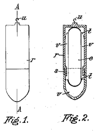
In these figures e is the reacting substance, which preferably has the form of a cartridge both ends of which are rounded off, and r is a capsule or casing made of two parts for receiving and carrying the cartridge e of reacting substance during the operation of searching for treasures of the soil or of testing' or analysing substances. The two parts of the capsule are preferably, screw-threaded as shown at s, for the purpose of joining them together in a manner more or less air-tight. That part of the capsule which, in its position for use, will be the lower one, may advantageously be tapered off to form a plummet.
In the interior of the two parts of the capsule r bearings t, t are arranged preferably near the top and bottom for the purpose of receiving the ends of the cartridge e of reacting substance and retaining them firmly when the capsule is closed. These bearings t, t are preferably perforated and fixed by means of narrow bridges to the interior surface of the capsule r.
The object of this arrangement is to provide a continuous layer or mantle r of air between the interior surface of the capsule or casing r and the cartridge e of the reacting substance within it.
The capsule r may removably be fixed or; suspended to an apparatus of the kind shown and described in my prior Specification Serial No. 146,840 by means of a hook and eye u or by any other suitable way.
The mode of operation of the arrangement described as before is as follows:For the purpose of searching for a treasure of the soil of any predetermined kind or for testing, or analysing substances, the capsule r is opened by separating the two parts of it from one another, a cartridge of a substance exactly reacting to the emanations radiated by this treasure, put into the capsule and the two parts of it closed again. Then, the reacting substance within the capsule -r is surrounded by a continuous laver of air, which if a treasure of the soil is present, may immediately be saturated s0 with emanations radiated by this treasure.
By this fact an action as strong as possible is exerted on the reacting substance and by this moreover the substance takes rapidly and exactly the direction of the actually present treasure or a direction 65 opposite to this.
The reacting substances to be used are generally the same as the treasures of the soil to be searched for or the substances to b)e tested or analysed. So e.y. for indicating the presence of water, petroleum, coals, gold and the like, the most suitable reacting substances to be used are again water, petroleum, coal, gold and the like. 75 For the better understanding of my invention I shall describe same by way of example in connection with finding sweet water. I open the capsule ', enclose therein a cartridge e containing 8( sweet water, close the capsule again tight and attach the same b v means of the hook and eve ut to the free end of the inclined swinging branch a of my apparatus as described and shown in prior Specification Serial No. 146,840.
As to the exact forces causing the apparatus to work as described 1 do not intend to make a definite statement though at the present state of develop- 9( menit of the method it occurs to me that the air surrounding the substance e within the capsule r, i.e. the water in the cartridge e, appears to be gradually saturated with emanations radiated by 91 the water inll the oround. A strong reaction takes place between the water ill the cartridge and that in the ground, the emanations causing the swinging branch a of my apparatus to move laterally and, if strong enough, imparting rotation to the whole apparatus around its axis.
Any organic or mineral, or metallic substance in, as well as above, the ground 10 answers my method if I put a cartridge.
formed of the same substance as that expected inl the ground, as a reacting substance into the capsule r. In such cases where a mineral of unknown character I( is supposed to be in the ground I therefore put one reacting substance after another into the capsule r, and carry the apparatus with the capsule into the sphere of action of the emanations radiated by 11I this substance until I find the one reacting substance which is so near in its character, or nature, to the substance in the ground that it causes the apparatus to work in the manner described. It occurs 121 occasionally that a reacting substance does not work readily enough upon the apparatus because the composition of the reacting- substance does not correspond to that of the substance in the ground. In 12, this case the reacting substance is modified in its composition until one is found which causes the apparatus to rotate or swing in the most definite manner. In locating a substance in the ground I am not always restricted to the use of a reacting substance of the same kind, or nature, as I have found that there are often several substances of good indicating power for the same substance. For instance I can also find water by using a cartridge of a mixture of tungsten, steel, metallic copper, metallic nickel, metallic manganese and metallic mercury, the results being as good as with water itself as a reacting substance.
For using my apparatus, with the cartridge of reacting substance e as described before, for testing or analysing substances of unknown character, I proceed in the same manner as described before, that is to say, I open the capsule, put a cartridge of reacting substance into the capsule, close it again tightly, attach the same to the free end of the swinging branch of my apparatus, bring it into the sphere of action of the emanations radiated by the substances to be tested or analysed, wait for some time till the mantle of air surrounding the cartridge or reactingÀ substance within the capsule r may be saturated with the emanations and if no action of the apparatus may be seen, I exchange the cartridge of reacting substance used for another and I proceed in this manner until I find the one reacting substance being near in its character, or nature, to the substance to be tested or analysed or to one of its constituents that it causes the apparatus to work in the manner as described in my prior Specification Serial No. 146,840.
GB146840
Improvements in apparatus of the divining-rod type for detecting the presence of subterranean substances and for like purposes
Improvements in apparatus of the divining-rod type for detecting the presence of subterranean substances and for like purposes
Inventor(s): PHILIPP SCHERMULY
Prospecting and water-finding. - Minerals, coal, water, oil, &c. are located by divining-rod apparatus comprising a rod a of steel, iron, copper, or other metal, or of a combination of metals, or of wood, rattan, whalebone, &c. which is suitably coiled to form elastically - connected branches, one branch being supported in bearings b and the other branch, which passes through a slotted graduated guide c, being graduated and free to oscillate and adjustably carrying a spring or slide d to which is suspended a reacting substance or a container e therefor. In a modification, two rods a, Fig. 3, are pivoted on a stud g by means of a spring ring h. The apparatus may be inverted and is stated to be applicable for analysing and testing purposes. The reacting substance is preferably of the same nature as the substance sought for, but sulphur may be employed in gold-finding and a mixture of specified metals in water-finding. Specification 979/12 is referred to.
My invention has reference to improvements in or relating to apparatus used for indicating the presence of treasures of the soil, i.e. water, minerals or metals, petroleum (naphtha), coals and the like, asl is the case in using a divining rod in the well known manner, and the object of mv improvements is to indicate the presence and the resting place of such treasures in a surer and more rapid manner than has hitherto been the case and furthermore to serve as an appliance for testing or analysing substances.
This invention is based on the discovery that emanations (dynamical effects) radiated by certain kinds of treasures) physically react on certain other substances suspended in such a way that these substances, in the following called " reacting substances," may either be attracted or repelled by these emanations.
I am aware that in the British Specification No. 979 A.D. 1912 a device for locating the presence of water minerals and the like, has been proposed in which a recording device is provided in conjunction with a divining rod for recording the amount of attraction or pull upon the same when in use. But in [., this device the rod is of usual shape with a fork the two branches of which are rigidly secured to one another and the ends of these branches bent at right angles are journaled in bearings in a 45 frame or casing so that the fork may only move in the manner of the usual divining rod, that is to say, in a vertical direction and the recording device connected to the rod may only give an 50 indication from the degree of attraction exerted from the water, minerals or the like on the rod itself and therefore from the depth at which the liquid or mineral sou',ht is located in the ground. 55 With my invention on the contrary, by using a device comprising, a fork made of two elastically combined branches, one of which forms the axis of rotation of the device, the other being 60 free to swing vertically to the first-named and detachably carrying a cartridge of substance reacting on the emanations radiated bv the treasures of the soil or other substances, I am able 65 to determine the kind or nature of this treasure or substance, and to read off the amount of rotation of the device on one scale and the amount of attraction or repulsion of the swinging branch of the 70 rod on another scale and in this manner to fix in all eases the thickness, depth of resting and quality of the treasure of the soil as specified before on the basis of practical knowledge and calculation, so that mv invention wholly differs from that which is known not only in its arrangement but also in its means of operation, its mode of working and results. My invention will be fully described with reference to the accompanying drawings, in which, Fig. 1 is a side view of the apparatus made ill accordance with the invention, Fig. 2 is a front view of the same and Figs. o to 5 are details of modified constructions of this apparatus.

In carrying out my invention I employ a thin rod of ally suitable cross-section and material, such as metal, steel, iron, copper and the like, or of a combination of metals, of wood, rattan, whalebone and the like, which rod may 15) preferably be bent in its middle part so as to form two branches a,, a elastically combined with one another by means of an ear or its equivalent as shown in Figs. 1, 2 & 5 or in any other suitable manner as shown in Figure 4 and including an acute or right angle, or the branches a, a may be made of two separate sticks, ends of which are pivoted on a stud g by means of a spring-tensioned ring h, Fig..8. Pivots j are provided at both ends of one of these branches a, a to enter eves of two bearings b, b directly to be held by the hands of a person or firmly united together by means of a suitable carrier to enable the branch to be turned within the bearings b. The other branch a is passed through a slotted guide c secured to the pivoted branch so as to be adapted to oscillate within this guide and adjustably carries a slide or spring d for lengthening or shortening this branch in case of necessity. To this slide or spring d a substance reacting on emanations radiated by the special treasure of the soil, to be searched for or by other substances to be tested or analysed, may detach ably and exchangeably be suspended, either directly or enclosed within a casing or capsule e, by means of hook and eye or in any other well known manner.
The swinging branch a is provided with a scale j for reading. off the shifting of the slide or spring d on this b)ranch and the guide c with a scale i for fixing the arc of oscillation of the swinging branch a within this guide.
Instead of making use of the apparatus in the position shown in Figs. 1 and 2 viz.: with the two branches a, a. diverging downward, the apparatus may also be used in a position opposite to that, that is to say, with the two branches diverging upward. In using the apparatus in this position, a more rapid rotation and hence a greater sensibility of the apparatus itself may be obtained.
The mode of working of the apparatus 65 is as follows:With the object of searching for a certain treasure of the soil, a cartridge of a substance e, especially reacting on the emanations radiated by this treasure, 70 is attached to the oscillating branch a of the apparatus dither directly or enclosed within a capsule or casing.
Now, if in the open country the apparatus with the reacting substance is -75 brought near to a resting place of the treasure of the soil searched for, the emanations radiated b.y this treasure first saturate the substance e and then produce a rotation of the pivoted 80 branch a of the apparatus in its bearings or seats b and, by means of an effect of physical nature, the oscillating branch a is at the same time oscillated, rotated, and attracted or repelled 85 till it comes to rest and, according to attraction or repulsion, points exactly in the direction in which the treasure of the soil sought for is resting or in a direction opposite to this. If the person carrying my apparatus, is just above the treasure of the soil the apparatus works in the manner of a regulator, that is to say, if, for instance, running lodes or stratifications of petroleum or 95 the like are present, it points in the general direction of strike and in so far as it is not in the direction of strike it faces the direction,of the flow.
The position of the two branches a, a 100 relatively to one another, resulting from the different actions of attraction and repulsion, speed 'of oscillation and rotation, kind and quantity of the reacting substance e., length of the oscillating branch a and the like, which position may be read off in the scales i on guide c and j on oscillating branch a, permits a conclusion being drawn as to thickness, depth of resting and quality 110 of the treasure of the soil found on the basis of practical knowledge and calculation.
For the better understanding of my invention I shall describe the same, by 115 way of example, in connection with finding sweet water. I use a capsule e, preferably in the form of a cartridge containing sweet water and attach the same by means of a hook and eye to the 120 free end,of the inclined oscillating branch a. of my apparatus. As to the exact forces causing the apparatus to work as described before, I do not Cj J 146,840 3 intend to make a definite statement though at the present state of development of the method it occurs to me that the water in the capsule e appears to be a gradually saturated with emanations radiated by the water in the ground.
Then, a strong reaction takes place between the water in the capsule e and that in the ground, the emanations causing the oscillating branch a of my apparatus to move laterally and, if strong enough, imparting rotation to the whole apparatus around its axis.
Any organic or mineral, or metallic substances in, as well as above, the ground answers my method if I use the same substance as that expected in the ground, as a reacting substance in the capsule e. The reacting substances to be used with my apparatus are generally of the same kind, or nature, as the treasures of the soil to lIe searched for or the substance to be tested or analysed themselves, that is to say, for indicating the presence of water, petroleum, coal, gold and the like, the most suitable reacting substances to be used are again water, petroleum, coal, gold and the like, but by numerous tests I have found that any other substances of chemical oI physical affinity to the substances to be searched for, tested or analysed, may also be used as reacting substances, as for instance, sulphur as a reacting substance for searching for, testing or analysing gold, a mixture of metallic copper, metallic nickel, metallic manganese, metallic mercury and tungsten steel as a reacting substance for searching for, testing or analysing sweet water and the like.
In cases where a mineral or other substance of unknown character is supposed to be in the ground, I attach one reacting substance after another to the free end of the oscillating branch a of my apparatus until I find the one which is so near in its character, or nature, to the substance in the, ground that it causes the apparatus to work in the manner described. It occurs occasionally that a reacting substance does not work readily enough upon the apparatus because the composition of the reacting substance does not correspond to that of the substance in the ground.
In this case the reacting substance is modified in its composition until one is found which causes the apparatus to rotate or swing in the most definite manner.
For using my apparatus for testing or analysing substances of unknown character, I proceed in the same manner as described before, that is to say, I 65 attach reacting substances of different character, or nature, one after another to the free end of the oscillating branch a,of my apparatus, holding the apparatus above the substance to be tested, and I 70 proceed in this manner until I find the one reacting substance being so near in its character, or nature, to the substance to be tested or analysed, or to one of the constituents of this substance, that 75 it causes the apparatus to work in the manner previously described..
GB147052
Improvements in apparatus of the divining-rod type for detecting the presence of subterranean substances and for like purposes
Improvements in apparatus of the divining-rod type for detecting the presence of subterranean substances and for like purposes
Also published as: AT81871 / CH94489 / FR534054
Inventor(s): PHILIPP SCHERMULY
Addition to 146,840. Prospecting and water-finding. Divining-rod apparatus as described in the parent Specification is provided with a compass k for indicating the direction of a vein of mineral &c. and with a speed-indicator m for indicating the number of oscillations of the rod. A pointer o on the rod co-operates with the compass. The compass and speed-indicator are connected by a rod l, and the whole may be supported on a post p by a ball- and-socket joint. The Specification as open to inspection under Sect. 91 (3) (a) describes also the application of a compass k and speed-indicator m to apparatus as shown in Fig. 5, wherein opposite ends of a coiled divining-rod a are supported in bearings in a circular or other frame l. This subject matter does not appear in the Specification as accepted.
This invention has reference to apparatus used for indicating the presence of certain treasures of the soil, water, minerals or metals, petroleum (naphtha), coals or the like, and constitutes an improvement in or modification of the invention of my Application for Letters Patent No. 146,840 in which a stick or rod of wood, metal or other suitable material is bent or coiled up at its middle so as to form two branches elastically combined with one another and to which may detachably and exchangeably be attached a cartridge of a substance react- ing on the emanations radiated by the treasures of the soil searched for or by other substances to be tested or analysed.
I am aware that in the British Specification No. 979 A.1). 1912, a device for locating the presence of water, minerals and the 'like, has been proposed in which in conjunction with a divining rod, an appliance is provided for recording the amount of attraction or pull upon the divining rod. But in this device the divining rod itself is of usual shape, that is to say, the two branches of the rod are rigidly, secured to one another and the rod is journaled in bearings in a frame or casing and the recording device is connected to the joint of the branches by means of a cord or the like.
By this arrangement, the rod may only move in the manner of the usual divining rod, that is -to say, in a vertical direction and the recording device connected to the rod only gives an indication of the degree of attraction exerted by the water, minerals or the like on the rod itself and therefore of the depth at which the liquid or mineral sought is located in the ground.
In opposition to this known device, in my apparatus I use cartridges of substances reacting to the emanations radiated by the treasures of the soil or by the substances to be tested or analysed detachably and exchangeably connected to the rod and the rod is rotateably inserted between a compass and a speed-indicator both adjustably fixed to a connecting bar so that the bar may easily' be put in or removed from the apparatus.
The object of this arrangement is to render it possible to read off directly the number of oscillations of the apparatus produced by the emanations radiated. by the treasures of the soil or the substances to be tested or analysed, in the speed-indicator and furthermore the direction of strike of the treasure of the soil as to 'degrees, minutes and seconds in the com- pass. Dry invention therefore wholly differs from that which is known in its arrangement as well as in its mode of working and results.
My invention will be fully described with reference to the accompanying drawings in which,
Fig. 1. is a side view,
Fig. 2 is a front view and
Fig. 3 is a, plan of my apparatus.

In these figures a, a are two branches elastically combined with one another of thin rod or stick bent or coiled up at its middle so that the two branches form an acute or a right angle, c is a slotted guide fixed to the branch formic the axis of rotation of the apparatus and is provided with a scale i.
d is a slide or spring adjustably carried by the other branch a, provided with a scale and elastically combined with the first-named branch, c is a reacting substance, preferably made in the form of a cartridge, detachably and exchangeably suspended from the slide or spring d.
This arrangement of my apparatus is essentially the same as that described and shown in my prior Specification Serial No. 146,840.
In accordance with my present invention : is 1 compass and a speed-indicator both preferably adjustably fixed to a connecting bar 1 to permit ready insertion of the branch a forming the axis of' rotation of the apparatus between the compass and speed-indicator and its removal from this position. One end of this branch is, with its pivot f rotateably mounted on the centre of the compass k and the other end is inserted within the speed-indicator m so as to form the axis of the same. o is a pointer suitably fixed to the pivoted branch a preferably closely above the compass 7, directed at right angles to the plane of the two branches a, a of the apparatus p is a post to which the apparatus may be fixed by means of ball and socket joint or in any other suitable way.
The mode of working of this arrangement. of my apparatus is as follows --- If the apparatus with the reacting substance attached to the branch is brought near to the resting, place of a treasure of the soil searched for and the reacting substance is of the. same kind, or nature, as, or of chemical or physical affinity to, the treasure in the ground, the emanations radiated by this treasure react on the substance and produce a rotation of the pivoted branch or of both branches n, fit in their seats and by means of an effect of physical nature, the oscillating branch a i.s at the same time oscillated, rotated and attracted or repelled till it comes to rest and according to attraction or repulsion, points exactly in the direction where the treasure of the soil searched for rests in the ground or in a direction opposite to that.
The position of the two branches n, fit relatively to one another resulting from the different action of attraction and repulsion, speed 'of oscillation and rotation, kind find Quantity of the reacting substance e,, and length of the oscillating branch a, which position may be read off on the scales i and j, on guide c and oscillating branch a respectively permits a conclusion being ,drawn as to thickness, depth of resting and quality of the treasure of the soil found, on the basis of a practical knowledge and calculation.
The number of oscillations of the branches a,may be read off directly in the speed-indicator m and the direction of strike of the treasure of the soil as to degrees, minutes and seconds by means of
the pointer () fixed to-the pivoted branch (i directly above the compass k.
With the object of using my present apparatus, for testing or analysing substances of unknown character I proceed in the same manner, as described before, that is to say, I attach reacting substances of 'different character, or nature, one after another to the free end of the oscillating branch a of the apparatus and I continue in 'this manner until I find a reacting substance so near in its character, or nature, to the substance to be tested or analysed, or to one of the constituents of this 'substance that it causes the apparatus to work in the manner previously described.
GB879568
Appliances for detecting the presence of water, metals and other materials
Appliances for detecting the presence of water, metals and other materials
Inventor(s): LAWRENCE JOHN VEALE
A device for detecting water, metals and other materials comprises an L-shaped metal rod the limb 3 of which is rotateably supported in a tube 5. In use two of the devices are held one in each hand of the operator with the limbs 2 of each rod pointing forward, the limbs 2 converging on the presence of the material or objects to be detected. The tube is of copper and contains a sleeve 8 for reception of the limb 3 of the rod which is chromium plated. The sleeve is surrounded by floating copper discs 10 which divide the tube into compartments 12, 13, 14 respectively containing copper needles 15, springs 17 and metal filings 14. In a modification the limb 2 carries a wire having the form of a sine curve.
This invention relates to an appliance for detecting the presence of water, metals and other materials.
According to this invention the appliance comprises an L-shaped metal rod, the lower upright limb of which depends into a metal tube, the said depending portion being sup ported at the longitudinal axis of the tube in spaced relation from the tubular wall, and is capable of rotation about the said axis. Two of such appliances are held one in each hand of the prospector with the horizontal limb of each rod pointing forward. The presence of water or metals is indicated by a deviation of the horizontal limb from the forwardly pointing position.
One form of the invention is illustrated in the accompanying drawing, wherein:
Fig. 1 is a sectional elevation;
Fig. 2 is a sectional plan taken on the line 2-2 of Fig. 1;
Fig. 3 is a perspective view of the appliance in use, and
Fig. 4 is a modified form of rod.

Referring to Figs. 1 to 3, an L-shaped chromium-plated rod of one eighth inch diameter has a horizontal portion 2 two feet in length and a vertical portion 3 nine inches in length. If desired, the rod can be made in two parts for convenience of transport, the two parts being joined by a sleeve 4 into which the two parts are screw-threaded.
The vertical portion 3 of the said rod is adapted to depend into a cylindrical copper tube 5 three quarters of an inch in diameter, nine inches inches, and closed at the lower end by means of a cap 6 made of brass. There is also a top cap 7 which is bored to take an inner sleeve 8 which is five sixteenths of an inch in diameter and sealed at the base 9.
The interior of the tube is divided into compartments by floating cooper discs 10 the outer edges of which just clear the inner surface of the tube 5. Each disc 10 has an aperture 11 in the centre to receive the sleeve 8 and vertical limb 3 of the rod. The discs 10 divide the tube into needle compartments 12, spring compartments 13 and dust compartments 14. Each needle compartment 12 contains eight cooper needles 15 having a pin point at each end adapted to seat in dimples provided in the surface of the discs, the said dimples being arranged so that the needles 15 are spaced in a circle around the axis of the tube 5. The compartments 14 are filled with metal filings 16, for example, brass or cooper dust, and the spring compartments 13 each contain a light gauge coil spring 17 the purpose of which is to hold the needles 15 in position.
In use, the vertical limb 3 of the rod is placed in he sleeve 8 in the tube 5 where it is just balanced to say in the position in which it is placed, but will rotate about a vertical axis on very slight movement. Two of such appliances are grasped one in each hand of the prospector about ten inches apart and the horizontal portions 2 of the rod are made to point forward. As the prospector moves over metal, water or other material or objects to be detected, the rods converge.
In order to make the appliance more sensitive the rod 2 may be provided with a wire 21, see Fig. 4, which serpentines in and cut through apertures 20 in the rod. Twenty-four loops are provided in all alternating above and below the rod 2. The distance between the crest of each loop and the rod is three quarters of an inch.
Other material or objects that can be detected by the use of the appliance are: water mains (iron or asbestos), concrete pipes, sewers F use or disused), stone drains, elec- tric cables underground, concrete o; wood floors) and reinforcing irons in concrete and many other substances.
The dimensions given above are by way of example only and can be varied to suit individual requirements.
FR2580821
Novel type of detection apparatus
Novel type of detection apparatus
Inventor(s): QUEHEN RENE
The present invention relates to a novel type of detection apparatus of the divining rod type. The apparatus according to the invention is characterised in that it consists of two metal rods 1, each of them being intended to be held in the hand of the user and in that each rod is bent and that the part 2 is capable of rotation around the part 3.
The present invention relates to a new kind of divining rod type detection device.
Known devices of this kind consist of a fork-shaped metal or wood which are especially moves to indicate the position of the water.
It was proposed several explanations for this phenomenon recognized but unsolved (Research YVES POLAR D No. 124, July August 1981)
The present invention is not intended to provide an answer to the question but provides an apparatus based on the principle and Me- displacement that allows me to detect the presence of water or other elements.
FIG 1 shows the apparatus according to the invention in a neutral operating position.
- Figures 2 and 3 show the device detecting-use position.
- Figure 4 shows the orientation of the rods
- 5 shows an embodiment chopsticks


The apparatus of the invention comprises two rods 1 each of which is intended to be held in one hand of the user.
Each strip is metal and is bent preferably at right angles by determining a portion 2 intended to be held in the hand of the user and a dwarf orthogonal part 3 to previous to be held horizontally or in a substantially horizontal position.
Part 3 is longer than Part 2.
When the neutral position using the two rods are substantially parallel (fig.l).
Upon detection on the principle of the two signed .u dowsing rods intersect (fig.2-3) when the operator passes over the éemitter source (metal mass, cavitated, water table).
In case the operator misses the source transmitter rice, moving two sticks is an unbalanced way (Figure 4) which deflects most while indicating the direction of the source emitter the path followed by 11 operator.
The rods are made of an electrically conductive material Meis part 3 can be mounted freely rotatable in a tube 4 e through which the user holds the tube 4 may be insulating.
The invention is particularly suited to the detection of water or other underground anomalies.
FR2446081
Divining rod with inset pearl - has central spiral and two branches which are joined to form setting for precious stone
Divining rod with inset pearl - has central spiral and two branches which are joined to form setting for precious stone
Inventor(s): KIRCHNER WILHELM
The divining rod has two branches (1, 2) with handles at their extremities, which are connected to a central spiral (11). The part of the spiral which is furthest from the handles has a setting (15) for a pearl (16) or any semi-precious, or precious stone. The rod is made from two identical pieces whose extremities are joined by soldering or braising. They are joined at two places (12, 13) so that the part between them (14) is curved outwards to form part of the setting for the stone.
The present invention relates to a divining rod comprising legs which extend from a middle spiral and each of which is provided with a handle at its free end.
We already know a divining rod of this type.
According to the invention, this known strip is improved in that it comprises on the spiral, in particular on the CBte of this spiral is farthest handles, a housing or holding device for holding preferably a bead, a semi-precious stone, a precious stone, or the like.

This housing or holding device for receiving the bead, or other member, is preferably designed as a cage, a frame, a ring, etc.
These shapes are particularly advantageous because they enable to use the same material as for the branches or the like.
In particular, they make it possible to realize the housing or retainer at least partly in one piece with the spiral.
Therefore, in a form of such a divining-rod which is especially preferred, it is proposed that the strip is composed of two identical parts which the former ends are joined by welding or brazing, these ends forming together at least one portion of the housing or retainer.
According to another feature of the invention, the ends of parts of the rod which are opposite the handle are welded to one another, or assembled in a similar way CON at two points spaced apart by a certain interval and the portion between these two points is curved outwardly according to the form of a ring, to form at least a portion of the housing or the bead retainer device, or other element.
In this embodiment, the expenditure is particularly low.
It is sufficient to slightly extend the rod tip and achieve a second assembly of the two halves of the stick, in particular by welding or soldering or by an equivalent assembly mode.
Another development of the invention is characterized by a bead, or the like, located inside the ring, which is traversed by a filamentary fixation member whose ends are connected to the wand.
It is particularly advantageous that both ends of the bead fastener, or other element, are attached to two points of welding, in particular by welding, brazing or equivalent means simultaneously with achieving two sources. The condition to be fulfilled is of course that the material on which the bead, or other element is inserted is constituted by a material suitable for welding, soldering or another similar assembly method.
Other features and advantages of the invention mparattront during the following description.
The accompanying drawing shows the divining rod of the invention in plan view and partly in longitudinal section.
The divining rod according to the invention is preferably composed of two parts 1 and 2 of the same length and the same configuration and the handles 3 and 4 respectively mounted on these parts rotatably.
The handles are adopted in axial translation with two flanges 5 and 6 on the ends Oete inontées handle-baguette, which are offset with respect to one another in the longitudinal direction and fixed for example by welding.
The handles 3 and 4 are tubular.
Between each handle 3 or 4 and the end 7 of the rod on which it is mounted, is a metal intermediate tube 8.
This tube may be made in the same way that the handles 3 and 4.
Its length can be the same or different handles.
The intermediate tube encloses the end 7 with a clearance which corresponds optimally to the needs, particularly as regards the material used for the baguette0 Similarly, one can also provide a game, not shown in the drawing, between each intermediate tube and the handle which surrounds the tube.
It failed to represent this game for graphics technical reasons.
At its end which forms the middle of the wand, each part of this rod is bent to form a loop of about one turn and the free end 9 or 10 which protrudes beyond this loop protruding from the loop to the outside in a radial direction.
Both ends 9 and 10 of parts 1 and 2 are assembled together, for example by welding.
It forms a kind of needle used, for example to a healer or doctor, to designate with great precision points or regions of the body of a patient or an animal.
The spiral 11 obtained in this embodiment and which comprises approximately two turns protects the assembly 12 in the shape of rod the divining-rod according to the invention against mechanical damage and tearing.
At a certain distance from the first assembly 12, is a second assembly 13 connecting the ext re- mites parts 1 and 2 of the strip which are furthest from the handle.
The two assemblies are preferably of the same constitution, that is to say that in both cases, they may be performed for example by welding or brazing.
To form a housing or retainer 15 to a bead 16, a semi-precious stone, a precious stone or the like, the portion 14 located between the two assemblies 12 and 13 is bent outward in a ring shape , that is to say, on each half of this part is formed at least approximately a half-ring.
To form a cage, one could also define a second ring, for example composed of two similar half-rings, which extend in a plane perpendicular to that of the first ring.
I1 is also possible and provided in the exemplary embodiment shown, use of the ring only as housing for the bead, or other element, and retain this bead or similar part by means of a filamentary fixation member 17 The ends of this element may be fixed by welding or soldering simultaneously with the welding of the joining points 12 and 13, which eliminates an extra work phase.
For the various chopsticks, you can choose different combinations of materials for the handle and stone, or other materials.
Thus, in the embodiment in question, it is planned to manufacture the outer sleeves handles money and use this metal in combination with a moonstone.
DE202005015433
Divining rod for therapeutic applications…
Divining rod for therapeutic applications…
Inventor(s): BLOEMER JOSEFINE
The divining rod has a cylindrical wooden handle (3) with a borehole in the centre and into which a brass sleeve (2) is inserted, where the rod utilizes high-quality materials. A helical compression spring (6) is inserted in the sleeve. Grooved ball bearings (4) are fixed on the top and bottom ends of the handle. A brass countersunk screw (1) is screwed-in to prevent the spring from getting thrown out of the sleeve. The ball bearings are fixed on the handle ends, in order to enable the compression spring to achieve uniform and fast rotation.

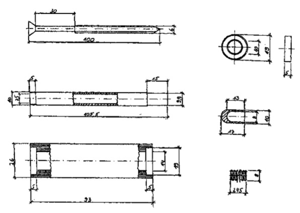
The radiesthesist has a cylindrical wooden handle (3) with a central hole in order to introduce a brass sleeve (2) can.
In this brass sleeve (2) is a helical compression spring (6) is introduced.
In order to bring the helical compression spring (6) in fast and smooth rotation, the upper and lower end of the wooden handle (3) Deep Groove Ball Bearings EZO 6800 2RS (4) are pressed.
Thus, the helical compression spring (6) is flying in the rotation not from the brass sleeve (2), a Messingsenkschraube M6x100mm (1) is introduced.
The brass end sleeve (5) to control the drive that is pressed onto the helical compression spring (6).
The radiesthesist represents an improvement of the pendulum in the traditional sense in quality, durability and design, since higher-quality materials are used and the processing allows higher loads.
The handling is facilitated in that the radiesthesist is passed through the entire palm.
In healer professions of any kind of radiesthesist can be used.
DE19517828
Deflection measuring device for divining rod
Deflection measuring device for divining rod
Inventor(s): GRUENAU DIETRICH
The device measures and documents the swing of a divining rod along a path. The free ends of the divining rod (20) are revoltingly arranged in handles (24, 25) and functionally connected with a sensor arrangement (mountings (26, 27; spokes 28, 29; stretch measuring strips (51, 52) which is electrically connected to an electronic evaluation circuit (computer 40; storage). A distance measuring arrangement or a GPS receiver may be used for determining and storing the coordinates of momentary position of the measurement.
The invention relates to a device with a divining rod for physical measurement and documentation of the deflection of the divining rod along a route.
The globe shows from one place to differences in the effects on humans, animals and plants.
The cause of action is not externally visible, their influence on the processes of life, the feeling of life, well-being and discomfort of organisms but perceptible.
It is known to produce the display of perception with a divining an unstable equilibrium, the capability provided learns in hand with the smallest differences in the physical condition of the ground a change.
The different strong deflection of the divining rod along a route or within a specified area has not documented.
The invention is based, to provide an apparatus of the aforementioned type, with the measurements of the deflection of the divining rod along a route and within a given area and the documentation of these measurements are possible the task.
According to the invention the object is achieved by the features recited in claim. 1
The invention has over the prior art on the benefits that a route along the deflection of a divining rod can be accurately measured and documented.
By measuring multiple lines side by side, a measurement field, are therefore a given area, measured and documented.
In this way a profile of the charisma of the soil along a predetermined path, and even a profile of a measuring field, ie an area, are created.
Depending on the characteristics of the recorded deflections of dowsing can be distinguished on the screen or on the printout according to various sources of radiation.
It can therefore be a water vein, a power line, etc. are detected.
On the screen or on the printout, a height profile can be created from which the intensity of the radiation at the location concerned and even the intensity distribution within an extended area are measured out unreadable.
Further advantageous embodiments of the invention will become apparent from the dependent claims and the following description.
The invention is illustrated by embodiments with reference to drawings.
FIG. 1, partly in section and partly in schematic, the inventive, working with a GPS receiver device,
FIG. 2 shows the equivalent circuit diagram in the form of a bridge circuit of strain gauges for the electrical measurement of bending moments on a divining rod,
Fig. 3 schematically an insulating body in the sphere of influence of a radiation field,
Fig. 4 schematically illustrates the measurement of the location at which the qualified person for dowsing is currently by means of a mechanical or electromechanical device


The apparatus 1 (Fig. 1) essentially comprises a divining 20 with a sensor, a GPS receiver 30 with a coupler, and a computer 40 having a screen 41, a memory and a downstream printer 42 for creating a printed protocol 43.
In one embodiment of the invention, the divining 20 consisting essentially formed by a wire 21, preferably in the form of a steel wire or copper.
Each of the free ends of the divining rod 20 is rotatably connected to a torsion bar 22, 23, which in turn is rotatably mounted in a handle 24, 25th
The free end of each handle 24, 25 expands to seat 26, 27 for fixed mounting a spoke 28, 29th
On each spoke 28, 29 is in each case a strain gauge 51, 52nd
At the strain gauge lines 53, 54 are electrically connected.
The lines 53, 54 are preferably brought together at the GPS receiver 30.
The latter is connected via a line 31 to a computer 40, a monitor 41 and a (not shown in the drawings) memory and, if necessary, a printer 42 of a Protocol 43 in the form of a graphic and / or in the form of text or Includes numbers.
The GPS receiver 30 (Global Positioning System) is used for the ground radio navigation for determining the coordinates of the position where the GPS receiver 30 and thus for dowsing qualified person is currently using the divining 20th
The equivalent circuit diagram (Fig. 2) of the strain gauges 51, 52 shows a bridge circuit consisting of resistors 55 for tensile and compressive stress resistors 56 for the strain gauges 51, 52.
At terminals 57 a supply voltage is applied.
The desired measuring signal is taken via terminals 58th
In one embodiment of the invention, resistors of 5 OMEGA were used.
The strain gauges are from the Company Measurements Group and have the designation TK-06-5082R-350th
The voltage applied to the terminals 57 supply voltage is 5 volts AC.
Measurement methods
Measurement with the aid of a GPS receiver to determine the current coordinates
The measurement of a distance and an area is made possible with the help of the GPS receiver 30, which is used to determine the current coordinates of the position of the dowsing qualified person holding the divining rod 20 in hands.
If the dowsing rod 20 (Fig. 1) held by the dowsing competent person at the handles 24, 25, the wire 21 of the divining rod 20 is rotationally pulled down.
This deflection of the wire 21 is so strong that twist the free ends of the wire 21 with the mind-rotatably mounted torsion bars 22, 23 with respect to the handles 24, 25th
By twisting the torsion bars 22, 23 with respect to the handles 24, 25 are the bent with their ends in the receptacles 26, 27 firmly clamped spokes 28, 29 and the strain gauges 51, 52 acted upon accordingly.
The at terminals 58 (Fig. 2) of the strain gauges 51, 52 emerging signals are via lines 53, 54 (Fig. 1), the GPS receiver 30 and the line 31 sent to the computer 40 for storage and evaluation.
Moves to the dowsing competent person along a given route, so that along this stretch changing intensity of earth radiation causes different strong deflections of divining 20th
Wearing the person also the GPS receiver 30 with it, so there will be a recording of the changing intensity of earth radiation along the route in Computer 40th
Next to each other measured in this way several routes, we obtain a two-dimensional gauging.
Directs an insulating body 60 (Fig. 3) Earth Radiation from, it is found that the field lines converge again above the insulating 60th
Even the history of earth radiation in the height above the ground with the described apparatus 1 in a manner analogous ausmessbar if one ensures that the amount of the respective measuring position is detected and each measured value is assigned.
Measurement with the aid of an electromechanical device for determining the current coordinates
The measurement of a distance and an area is also possible by means of a mechanical or electro-mechanical means for determining the current coordinates, which will be explained with reference to FIG. 4.
In this case, would be with a coupler on this map used in the device instead of the GPS receiver 30 shown in FIG. 1, only one coupler, which are used for merging of the lines 53, 54, and from which the computer 40 leading line 31 would depart.
At the dowsing qualified person 70 (Fig. 4), the ends of cords 71, 72 are hooked, whose other ends are each wound on a per se known drum 73, 74.
The cords 71, 72 for measuring the distances, which currently complies with the dowsing authorized person 70 to the respective drum 73, 74, always by means of suitable, known per se means, such as friction clutch or precise electromechanical control of the drums 73, 74 held taut.
The drums 73, 74 or the distance measurement serving lines 71, 72 are known per se encoders 75, 76 in a conventional manner in such a way in the functional connection that on which the for dowsing competent person 70 is currently in any place, , is well known how far away she is present from the respective drum 73, 74th
The encoders 75, 76 (Fig. 4) Report the determined values of them over (in the drawings not shown) leads to the computer 40 (FIG. 1).
To determine the absolute point at which the for dowsing competent person 70 is, evaluates one of the unwound lengths of the cords 71, 72 alpha means the values and angle supplied by the encoders 75, 76 and beta (Fig. 4) 72 which form the lines 71, at a predetermined distance 77 between the drums 73, 74th
Enter these values into the computer 40 (FIG. 1), this calculates the current coordinates at which the for dowsing competent person 70 is straight, it represents on the screen 41, records them and printed as desired, a graphic and / or Text or Figures from.
It's even easier to store the length of the distance 77 between the drums 73, 74 in the computer 40 (FIG. 1).
The computer 40 can then run the routes, which result from the unwound from the drums 73, 74 cords 71, 72, the coordinates of the location are calculated, at which the qualified person for dowsing 70 is currently located.
LIST OF REFERENCE NUMBERS
1 device
10 channel
11 input stage
12 pretreatment stage
13 filter bank
20 channel
21 input stage
22 pretreatment stage
23 filter bank
30
31 Performance measurement stage
32 additional treatment stage
33 Noise Reduction Level
34 reconstruction stage
35 output
40 line
DE4423279
Divining-rod for detecting geobiological stimuli
Divining-rod for detecting geobiological stimuli
Inventor(s): KEDING CARL ROBERT
The divining-rod has an electrically conductive fork with a pair of relatively spaced fork arms (3, 4), which are insulated at one end. The fork arms are contacted by respective electrical conductors (5, 6), lying at a distance from one another. Pref. the electrical conductors are provided by rods or plates which lie parallel to one another and which can slide axially relative to the fork arms. The latter may be coupled to a voltage source, with the electrical conductors coupled together via non-conductive coupling elements (7, 8).
The invention relates to a divining rod with an electrically conductive fork.
Dowsing can be used for detecting geobiological stimuli.
Here it is important to implement, for example from the ground emerging vibrations so that This results in a rash of Rute.
On the other hand, the dowsing themselves have a certain resonance function, so that their design is crucial for stimulus detection.
According to DE-A1 30 20 636 has been proposed to make the tip of the tail variable to react with adjustable size in different radiation can.
An extended antenna function of divining is in Page 154 described
With the Lecher line-rod shown there, it is possible to detect the radiation in the microwave range selectively.
Often give the known rods but only inadequate signals, so that it is the object of the present invention to provide a more dowsing which allows an even better stimulus detection.
According to the invention the solution of the problem according to the characterizing features of claim 1.
According to a particular embodiment of the invention, the electrical conductor rod or be plate-shaped, which can achieve a substantially parallel arrangement.
According to another embodiment of the invention, the electrical conductors are arranged axially on the fork parts.
This makes it possible that the divining rod resonates with certain vibrations, so that different stimuli can be selected.
Moreover, it is advantageous if the electrical conductors surround the uncontacted fork part without contact.
This allows the electrical conductor arranged in alignment, without causing an obstruction by the fork parts.
According to another embodiment of the invention, the fork parts can also be connected to a voltage source, whereby a better stimulus recording is made possible.
To stabilize the rod it has proven effective to fix the fork parts by non-conductive connecting elements.
According to a preferred embodiment of the invention may be connected, so that there is also for this a solid support with these fasteners turn the electrical conductors.
A preferred embodiment of the invention is illustrated in the drawings and will be described in more detail below.
FIG. 1, the divining rod in a schematic plan view,
FIG. 2 shows a section of two fork parts to the electrical conductors in a longitudinal section,
Fig. 3 shows a cross section through the fork along the line AA and
Fig. 4 shows a cross section through the fork along the line BB.


FIG. 1 shows a preferred embodiment of the invention in divining a schematic plan view.
In the illustrated embodiment, the fork on 2 different fork parts.
The fork members 3, 4 are arranged at a distance from one another and extend substantially parallel to each other.
They consist of an electrically conductive material, for example made of metal or carbon fibers, and are preferably rod-shaped.
Their cross-section may be round or square.
The Fork parts 3, 4 are insulated ends 9, 10th
At the opposite ends of this 11, 12 are the fork parts 3, 4 connected to handles 13, 14th
Typically for dowsing, the handgrips 13, 14 at an angle to the fork parts 3, 4 are arranged.
The handles 13, 14 may, like the fork parts 3, 4 made of a conductive material so that extend the fork parts 3, 4 as handles 13, 14 in the simple case.
When properly used, the dowsing can after receiving stimuli between the handles 13, 14 a tension arise, which can change the polarity according to individual circumstances.
According to a particular embodiment of the invention, it is also possible to connect the handles 13, 14 to a voltage source, in particular a direct-current source.
As a DC power source, for example, used a commercially available battery.
With a suitable design of the handles 13, 14, such a battery also be accommodated in the handles 13, 14, wherein a conductive connection between the ends 15, 16 is provided.
Applying a voltage has the advantage that, 6, an electric field is formed between the fork parts 3, 4 and the electrical conductors 5, whereby the male stimuli are better detected.
To fix the fork 2 can still be a holder 17 provided that, if the fork parts 3, 4 and the handles 13, 14 is not surrounded by an insulating layer of a nonconductive material such as Plexiglas exists.
The section magnification shown in FIG. 2 shows the specific characteristics of dowsing invention.
After this, the fork parts 3, 4 forming isolated, wherein the fork member 3 with an electrical conductor 5 and the fork part is 4 contacted with an electrical conductor. 6
The in spaced conductors 5, 6 are preferably rod-shaped or plate-shaped.
They can as well as the fork pieces 3, 4 are made of metal or other electrically conductive materials.
In a preferred manner, the electrical conductors 5, 6 with non-conductive connecting elements 7, 8 may be connected.
The connecting elements 7, 8 provide here is a position fixing the electrical conductors 5, 6 and are glued or screwed with this example.
A particularly simple mounting of the connecting elements 7, 8 can be z.
B. achieve characterized in that the connection elements 7, 8, the fork members 3, 4 having adapted holes 18-21, through which the fork members 3, 4 are performed.
In order to form an electric field, the electrical conductors 5, 6 are each connected to only one fork part 3 4.
In particular, it has proven advantageous if the non-contacted fork part 3, 4 is surrounded without contact of the respective electrical conductor 5,. 6
As shown in Fig. 3, the electrical conductor 5 for example, have an enlarged bore 22, whose diameter is greater than the diameter of the cradle member 4.
On the other hand, it is possible to provide, instead of the bore 22, a differently shaped recess 23, in which the fork part 3 may be placed without contact to the electrical conductors 6 (Fig. 4).
The divining invention has the advantage that changes the distance of the electrical conductors 5, vary. 6
The electrical conductors 5, 6 are arranged axially on the fork parts 3, 4 and can be fixed in any position z.
For example, by a locking screw 24th
By moving the electrical conductors 5, 6, the electric field can be changed, which is formed between the electrical conductors 5, 6, so that a selection of the male stimuli can take place.
DE4341366
Test instrument for divining
Test instrument for divining
Inventor(s): KRAMER FRITZ DR MED
The test instrument has a handle (12) and a vibration head (16) which is attached to the handle via a spring rod (14) and which can be set vibrating wrt. the handle. The free vibration length of the rod between the handle and the vibration head is adjustable and can be determined using a scale (46) on the instrument. The scale can be applied to the handle and the spring rod can carry a pointer (50) associated with the scale. The hollow handle has a guide element (30) and a fixing element (40). The spring rod extends into the hollow handle and can be moved by the guide element. The fixing element can fix the rod with a set length protruding .
The invention relates to a test instrument with a handle and a displaceable at this securable via a spring bar, vibrate against the handle pivoting head.
Such a test instrument is disclosed in DE 42 06 017 C1 of the applicant.
In this known test instrument Schwingkopf on the spring bar to the grip is so connected that there is a clearly identifiable spring free length, which means that the oscillation behavior of the oscillating head is precisely defined.
Thus, such a test instrument has precisely one resonance frequency.
The invention is based is to provide a test instrument of the aforementioned type that is optimally suited for different applications like looking for specific drugs, the search for water, searching geophatischer distortions etc. the task.
This object is inventively in a test instrument of the aforementioned type by that the free vibration length of the spring rod between the handle and the oscillating head is adjustable.
This adjustability of the free vibration length of the spring rod, it is possible, as required to accurately adjust the inventive test instrument to the respective application, in order for example after making the appropriate setting of the free spring rod length. Specific medication for a patient such as Heart means to be able to very precisely determine the appropriate reaction of the test instrument.
Likewise, the inventive test instrument suitable eg. For water search, search geophatischer distortions, to search electrical fields eg. Of underfloor heating systems, for the diagnosis of various human organs, ie which drugs for the corresponding organs are optimally finding.
So the spring free length of the spring rod is eg. Set to 13.5 cm when the inventive test instrument is applied to the water search, and it is the spring free length of the spring rod for example. Set to 28.7 cm when geophatische with the inventive test instrument faults be sought.
The figures latter provide naturally only represent examples, because it is understood that the respective adjustment of the free spring length of the spring rod between the oscillating head and the handle dependent both on the choice of materials for the spring bar as well as its cross-sectional dimensions or by the respective user of the test instrument are.
To provide anytime reproducible conditions in the inventive test instrument, it is advantageous if the test instrument is configured with a suitable scale, ie when the set free vibration length of the spring rod between the handle and the pivoting head can be detected by means of a provided on the test instrument scale.
This scale can On spring bar itself be provided in order to determine the respective free vibration length of the spring rod can.
After the spring bar itself, however, conveniently consists of a spring wire and, consequently, has only a small cross-sectional dimensions and thus a small surface area, so that the attachment of an appropriate scale may be difficult, it is advantageous if in the inventive test instrument, the scale is provided on the handle and when the spring bar is provided with a scale associated display element.
Said scale may be formed with a millimeter scale like a ruler mark, with a tariff classification or any other subdivision of the tick marks.
A simple design of the inventive test instrument is achieved when the handle is provided hollow and with a guide element and a fixing element when out verstellbeweglich with his from Schwingkopf remote first end through the guide element hineinerstreckt the spring bar into the hollow handle, and when the fixing to fixing a certain length of the handle is provided from the protruding portion of the spring rod.
With such a design of the test instrument, the handle may comprise a sleeve, which is provided at one, the oscillating head facing end with a closing piece which is formed with a guide member forming the guide rod through hole.
In the through hole, it usually is a through hole whose diameter is adapted to the diameter of the spring bar is usually formed from a spring wire.
A simple configuration, in a test instrument of the latter type is achieved when the sleeve and the closure piece are provided with a transverse bore which is formed with an internal thread, and when in the internally threaded transverse bore a fixing element forming for the spring rod screw is screwed ,
So even after a long term use of the test instrument suffers his respectability in any way, it is advantageous if the sleeve with the closure piece having an appropriate surface coating.
This surface coating can be a gold plating.
With an appropriate surface coating also forming the fixing screw and the set at the spring rod oscillating head is expediently provided.
A well and precisely in its free spring length adjustable spring rod, ie a precisely adjustable test instrument is feasible, if the handle is formed with a longitudinal slot, where the scale is provided, and when the display member on the first end portion in standing in the grip of the spring bar is arranged.
Here, the indicating element preferably has a circumferential contour which is adapted to the clear inside contour of the hollow grip piece.
In this way, in fact achieves that the spring bar mentioned not only by the above, provided on frame guide member is guided in a linearly movable, but also by the display element itself inside the hollow pistol grip.
There arise therefore two spaced apart guides of the spring bar, which means that the spring bar can be adjusted easily very precise after a corresponding unlocking of the fixing.
Thereafter, the fixing member is then operated again to fix the spring rod and maintain the set spring free length of the spring rod.
Is the spring free length of the spring rod is relatively short, so a vibration of the vibrating head with a relatively high frequency results in less vibration amplitude; is the spring free length of the spring rod large, it follows conversely a relatively low oscillation frequency at the same time relatively large vibration amplitude.
The display member may comprise a plate and an upstanding from the plate having fixing portion, wherein the plate has adapted to the inner contour of the hollow handle, the circumferential contour of the piece and the first end portion of the spring rod is fixed to the fixing portion.
Thus with a test instrument thus designed an accurate indication of each set free spring length of the spring rod is possible, the plates can be formed with a knife-like tapered peripheral contour.
An embodiment of the inventive test instrument is clipped in the drawing marked in a sectional view and is described below.
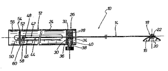
The pivoting head 16 is at one end portion 18 of the spring bar 14 for example. Means of a screw 20 and a fixed with this screw-nut 22nd
The handle 12 has a sleeve 24 in which the one end portion 26 a closure piece is fixed 28th
The closing piece 28 forms for the spring rod 14, a guide member 30th
To this end, the closure piece 28 is formed with a through hole 32nd
The spring bar 14, which is preferably a spring wire, extending through the through hole 32 without clearance through.
Through the sleeve 24 and in the closing piece 28 extends to the through hole 32 has a transverse bore 34 which is formed with an internal thread 36th
In the female threaded cross bore a screw 38 is screwed, the one fixing 40 forms for the spring bar 14 when the screw 38 is screwed into the internally threaded transverse hole that the screw 38 against the spring rod 14 and this thereby against the through-hole 32 is forced.
The sleeve 24 of the handle 12 is formed with a longitudinal slot 42 along its peripheral edge 44 on the outside of the sleeve 24 is a bar-scale 46 is provided.
The scale 46 may comprise a millimeter division, a customs classification or any other line-classification.
At the head from oscillating 16 distal end portion 48 of the spring bar 14, a display element is fixed 50th
The indicator member 50 comprises a plate 52 having a peripheral contour 54 which is adapted to the clear inside contour 56 of the sleeve 24 of the handle 12.
From the plate 52 is a fastening portion 58 away, is at which the spring bar 14 is fixed with its end 48th
It is fixed by eg. By means of a pin screw 60.
With a thus designed test instrument 10, the spring free length of the spring rod 14 between the locking piece 28 and the fixing member 40 and the oscillating head 16, it is easily possible to adjust as desired to make the test instrument 10 for the application appropriately sensitive.
The invention is of course not limited to the embodiment shown in the drawing of the test instrument.
DE4011344
Antenna for use as divining rod or for scientific investigation...
Antenna for use as divining rod or for scientific investigation...
Inventor(s): SCHNEIDER REINHARD
An anntenna which can be tuned for use as a divining rod and/or as an auxiliary aid for biophysical, physical and/or techanical investigations and other applications contains at least one variable resonant circuit for reception and transmission. The dimensions of the resonator circuit components are selected to produce a characteristics impedance corresp. to that of the vaccum or the medium in the reception or transmission chamber. The separate conductors of the resonant circuit have no fixed galvanically conducting mutual connections over theier entire lengths. The, pref, elastic, handles (45.1,45.2) are assigned to the carrier (21.2) or a slide (30) and can have markings (38). USE/ADVANTAGE - Can be used for long and very long wavelengths and in submillimetre range for field effect investigations, through absorption, emission, interference and/or resonance.
The invention relates to an as dowsing and / or as a tool for biophysical, physical and / or technical studies and / or interference and / or to the field affected by absorption, emission, interference and / or resonance deployable, tunable antenna having at least one abstrahlfähigen receive and resonant circuit, whose dimensions are variable, and wherein at least one arranged on a carrier printed circuit and at least inductively with him and / or capacitive and / or electrolytically cooperating components determine the resonance and said conductor width, conductor thickness, conductor cross-sectional shape, if necessary
Conductor spacing and / or distance to the vehicle and the ambient conditions of the resonant circuit are chosen such that in the resonant circuit, there is a characteristic impedance that matches the impedance of free space or the medium in the reception or transmission space.
Dowsing with the above features have long been used.
They are a systematic development of the usual time immemorial divining species and by the laws of physics were introduced antenna for viewing and use.
As a result, you can analyze or customize the considered phenomena more precisely.
It is also known for several decades, to use dowsing rods with built according to the principle of the Lecher line structures in which not enter the handles in the consideration of the antenna structure.
The design of spaced lines and their environmental conditions for the determination of the resonant circuit is used, namely by a tunable antenna is designed with at least one receiving and abstrahlfähigen resonant circuit whose dimensions are variable and wherein the distance run from each other, possibly converging or diverging lines, by at least inductively and / or capacitively and / or electrically active components (cross-connections) determine the resonant and said conductor width, conductor thickness, conductor cross-sectional shapes, conductor spacing and the working environment of the resonant circuit are selected such that the resonant circuit, there is a characteristic impedance of, or the impedance of free space the medium in the receiving or transmitting space corresponds.
In DE-OS 36 42 436 A1 is treated, how to make the bandwidth for the use of such technical antennas or divining by appropriate guidance and design of extending spaced conductors.
Here are to be received which, abzusendenden or indeed considerably enlarged to search wavelengths through the outer structure of Lecherleitungsgestaltung, however, is limited depending on the choice of greetings, and structuring of materials on 5 mm to 5 m wavelength.
In nature in biophysical processes in geomancy, the science of localized, acting mainly on the human vibration operations, and in the art, however, come within the range of the radio window also much larger wavelengths up in the longest long-wave range.
For biophysical studies, as well as technical and scientific studies, especially ancient places of worship and to lessons learned from them facilities are functional, which make it possible, with the simplest means to cover a very wide range of wavelengths, to the importance of each factor of a vibration event in a space be able to analyze.
For this is because of the great sensitivity and the large bandwidth of the biological system human divining the particular degree.
V-shaped divining rods are particularly suitable by its handling after the handle length and technology in the tuning technique of the applicant in order to quickly adapt to different phenomena.
The previous V-shaped divining rods were not equipped with adequate structures to receive long waves.
They were previously only suitable for the reception of wavelengths between a few cm and a few dm, up to a maximum in the range of wavelengths with some m.
The two V-shaped divining rods that are fixed at its upper end and in each case to be searched phenomenon well further conductively connected.
The previously known, used as an antenna for receiving and transmitting structures with conductor tracks according to the Lecherprinzip had always at any point an electrically conductive cross-connection, as is shown in particular also in the DE-OS 36 42 436 A1.
This spatially unchangeable cross-connection means that when placing a slide - no matter whether it is inductive or capacitive nature and / or additional components or not - the distance between the field comparatively authoritative reference point and the stationary, conducting cross-connection in the resonance behavior of the overall system enters in some way, if not this essentially determined.
Thereby, the wavelength range for reception and transmission is forcibly dependent on the geometric dimensions of some kind.
This dependence limits the use possibilities.
The invention has for its object to provide an antenna for technical and scientific purposes, for the influences of field events and / or as a divining rod by suitable design to equip so that they especially for the region of greater and greatest wavelengths, but possibly also to in the sub-millimeter range can be used, which are to be interpreted according to the criteria known from the antenna Physics and High Frequency Physics, and which is possibly used also for determining and / or modifying various portions of the field events.
The group of related inventions is the general inventive concept of the invention to provide open conductor systems of the type described in detail herein with other elements of the resonance determination and to make the design so that they are ideal for use as antennas for the purposes mentioned hereinbefore.
According to an essential part of the invention or of the group of inventions underlying general inventive concept is in particular provided that the conductors are configured as spaced over its entire length without a fixed electrically conducting connection with each other.
Use of an open Lecher line on a suitable support means that you can thereby determine free or at least free the received or radiated wavelength in a much larger area that the additionally attached devices, such as slides other with capacitive or inductive elements or own resonating circuits, Auxiliary equipment and possibly the attached handles can be influenced by the behavior with respect to wavelength, without being tied to the possibilities provided by the cross-connection conditions.
In DE-OS 36 42 436 A1 known antennas were already at angles to the main axis of the carrier or its manager handles and / or the receipt or
Transmission characteristic determining auxiliary antennas or auxiliary resonators mounted.
In the new training as an open Lecher the auxiliary antenna as in different lengths can be formed with your hands tangible rods in an important training.
Such rods can be formed in an advantageous manner as an elastic, dielectric antenna rods made of plastic.
According to an essential part of the invention or the group of inventions underlying general inventive concept can be provided in one embodiment, both with and without open Lecher especially that designed and usable according to the laws of the antenna physics divining with two bars and a holder designed for the bars, where the bars are at different distances from the field comparatively authoritative reference point with hands touchable, and wherein the holder receives the forces acting on the mutually approximated ends mechanical preload forces and is being further provided that the ends of the bars in the area the bracket with the respective to seekers, to be received or to be sent electrical, magnetic and / or mechanical (ponderomotive) phenomenon are not necessary to continue conducting and that an arrangement is provided in the bracket, the determining of the resonance and the characteristic impedance components a tunable resonant circuit forms, in its resonant wavelength enters the length between the respective tapping point and the field comparatively authoritative reference point.
Expressed divided, the divining the following characteristics:
- It is designed according to the laws of physics and antenna is used afterwards;
- She has two bars which are being handled by the user's hands;
- The bars are the biasing forces receptive connected at their ends close to each other;
- The rods are held with different lengths, free, the length of handle forming antenna lengths (distances) of the interconnected ends,
marked by following features:
- The holder of the ends of the rods is respectively to seekers, to be received or to be sent electrical, magnetic and / or mechanical (ponderomotive) phenomenon formed virtually unaffected continue conducting;
- In the region of the holder is provided with an arrangement of components which form a resonant circuit which is tuned to the desired impedance and the resonance under consideration.
This part of the invention is based on the realization that, although a mechanical support for the rods is necessary to absorb the forces to be applied, that this support but not necessarily also needs very specific properties for the electrical, magnetic and / or ponderomotive phenomena exhibit, but that they are designed appropriately so that it has no significant impact on the work result with regard to these phenomena, but that one rather apart from the mechanical support an arrangement with suitable components providing that both the resonance with respect to the eligible wavelength and the characteristic impedance the overall arrangement allows to determine the appropriate design as an antenna and / or divining.
Now that the mechanical function of the support is separated from the actual physical function of the holding portion, can be provided at this location suitable aids to quickly adjust the overall arrangement of the respective wavelength.
The well-known from the high- and low-frequency technology and communications technology and wireless transmission technology structural elements and components can now sense selected and the mechanical mounting of the ends assigned by V-shaped divining rods, thus resulting in an overall system of a divining rod, which extends through the wavelengths defining components with an extremely large bandwidth allows an unexpectedly simple means and adapt very quickly.
These can be used alone or in conjunction with one another on the one hand, the known from the dimensioned as Lecher divining structural elements, on the other, which are known from the design of resonant circuits with capacitors and inductors and devices known from the cavity and -leitertechnik facilities.
An important design feature for the opportunity to substantially increase the resonance wavelength of the entire system, is the provision of an open-ended Lecher both ends of parallel or divergent or convergent ladders.
The spaced conductors over their entire length without a fixed ohmic contact with each other are performed.
This is then assigned to a cross-connection which can be configured as electrically conductive connection, as a capacitive or an inductive or a compound semiconductor.
By selecting the dimensions and materials determines the built-up with this conductor system resonant circuit in conjunction with the free grip length of the rods, the effective antenna length.
In a design independently selected from the training, assembly and the use of the bars can open to either side Lecher also in connection with arranged at angles of the order of 90 °, used short handles for various purposes in conjunction with other configurations and components become.
It determines in particular the configuration of the Lecher line and the design of the intended on their slides and / or on the support arrangement, the resonance wavelength and the characteristic impedance.
Through appropriate training on the slider, for example, with an adjustable small cavity, you can use the same antenna arrangement for briefest mm-wavelengths, for example, by designing a mixed addition of the associated element.
One can by changing the arrangement of the handles in one of the V-shaped divining appropriate configuration then without much further aids to the alternate receipt or sending or searching of briefest and allerlängsten wavelengths pass.
It has been recognized that the angle between the respective conductor track the Lecher line and the handle-like rod of material influence on the resonance wavelength of the whole system is.
If the angle of the order of 90 °, so the free length is between the hand and the connection of the rod to the track of Lechersystems only smaller active component in the resonant wavelength of the entire system a.
If the angle between the conductor and rod connection below about 80 °, so the free length is between the hand and the connection of the rod to the conductor as an independent, free antenna length in the overall system and, in conjunction with the design of the arrangement in the region the holder for a substantial part of the resonant wavelength.
It should be stated that because of the openness of Lechersystems the handles are equal to the angles at which they completely connected, enter into the determination of the resonance wavelength.
The approximately at right angles connected handles can not handle with distance and hence greater length of handle you.
Therefore, it is conveniently on the V-shaped arrangement of the handles on the carrier or slide.
The handles or formed as auxiliary antennas rods can be formed on a variety of known types, in particular as an elastic dielectric antenna rods of plastic.
In a particularly advantageous development of the invention it can be provided that the plastic bars are fastened to optionally adjustable angle brackets.
Furthermore, it can be provided in a particularly advantageous manner in that the bars are made of materials with semiconductor properties.
Further, the rods can be designed as telescopic rods.
The rods are preferably about 0.2 to 1 m long and about 2 to 8 mm thick.
Setting and reading can significantly improve and simplify, when the bars with embossed and / or printed scales and / or markings are provided.
Particularly favorable usage and setting conditions arise if the holders for the rods approximately in the middle of the total length of the guided spaced conductors are arranged.
A particularly important aspect of the invention provides that, for a antenna according to the embodiment described here, but also by known Lecher Prinzip- embodiments in which the conductors is associated with resistive, inductive and / or capacitive coupling of a slider which supports the rods are attached to the slider and cooperating with the conductors through resistive compounds or are coupled to these inductively and / or capacitively.
Then you can easily replace the carrier with conductor paths to the same to use different properties for the overall system and can also be on one side or the other or both sides of the slide with the handles put one or more further slide same or different configuration and thereby the diversity the deployment and usage options significantly increase.
Another particularly important aspect of the invention provides that, for a antenna according to the herein described embodiment, but also by known Lecher Principle embodiments, the conductors at least a slider is associated with which at least an adjustable capacitor and / or at least an adjustable inductance are included.
It can be advantageously provided that the slider is equipped with a switch that either the galvanic connection, the capacitive and / or inductive connection of the conductors on and off permitted.
Another important aspect of the invention provides that on the back of the wearer's another Lecherleitungsform, for example, a converging / diverging arrangement and / or an arrangement with fixed cross-connection at the end or formed somewhere between the ends.
With such a device, you can, if necessary, in conjunction with the work in the rest of this application and / or by reacting shifters with additional facilities in accordance with the principles of the various Lecherantennen types simultaneously or in rapid succession.
By placing several slides, each operating on the associated web page, you can also vote the antenna structure several to be received or abzusendende wavelengths simultaneously and so examine spatial areas to determine whether they contained field conditions that exactly the two resonance wavelengths of the two sides justice and / or contain their electric or magnetic component.
Another important aspect of the invention provides that a plurality of conductor track systems are arranged in the plane or in space to at least a three-sided prismatic or otherwise shaped body.
This can be received different physical phenomena and / or transmitted and / or affected simultaneously several with respect to wavelength and or their other physical properties.
This phenomena can be analyzed and / or transmitted or corresponding fields are influenced simultaneously and / or generated Coupled and / or modulated.
The conductor tracks may be provided on a support is even and / or odd.
Especially odd interconnect configurations allow through the respective center-conductor particularly versatile couplings.
This resistive, inductive and capacitive coupling members and resonance-determining components can be assigned to the respective outer conductor and the common central conductor koppelnd each simultaneously.
In this case, non-linear mixing members may be arranged in the active compound.
Further details, advantages, features and aspects of the invention, as well as thoughts and explanation of its use and procedural instructions for the creation of measurement arrangements with the antennas, their configurations and additional elements are also evident in the claims and the subsequent, treated of reference to the drawings Description part.
Embodiments of the invention are dargesteIlt schematically in the drawings, for the most part and are explained with reference to the drawings.
Shown are:
Figure 1 is a schematic plan view of an antenna with the basic elements, as they are also used in the further figures.
2 shows a cross section along the line 2-2 in Figure 1 through the antenna..;
Fig. 3 is a simplified view corresponding to Figure 1 an antenna with a slider.
Fig. 4 is a plan view of a further, much longer and therefore interrupted illustrated antenna with a slider and fasteners on the slide and on the support of the antenna with a conductive connection to the conductor tracks and two selectively attachable to the fixing devices of the support or of the slide handles;
Fig. 5 is a representation corresponding to Figure 4 of another embodiment of an antenna with interchangeable and mountable at different angles, rigid handles.
FIG. 6 is an illustration corresponding to FIG 5 with flexible handles.
Fig. 7 is a similar to FIG. Representation of an antenna carrier with six conductive tracks each of which a pair of identical, but which has to the other of different length, wherein the antenna with the corresponding additional elements as for the antenna systems of FIGS. 3 to 6 and also 1 is shown in FIG 2 usable and useful.
8 is a plan view of an antenna with three conductors and two slides, but without handles or other coupling means.
FIG. 9 is a representation of Figure 8 corresponding with five conductor tracks, various slides shown schematically and two handles.
Fig. 10 is a schematic plan view of an antenna with five conductor tracks, wherein the other components are not shown, but can be attached and assigned according to the previously discussed figures.


Figs. 1 and 2 show the basic shape of an antenna as a first embodiment of the invention illustrating a first variant.
On a substrate 21, the two interconnects are 25.1 and 25.2 mounted at a distance A from each other.
These each have the width b and the thickness d.
In this case - explained 36 42 436 A1 in more detail in DE-OS - b to reduce the width for an end.
At the same time may be reduced according to the distance A.
The thickness d may be variable, but this is difficult to implement in practice.
The conductors 25.1 and 25.2 can be configured as a structure variable dielectric properties can be obtained as a metallic conductor or as a semiconductor or in the manner described in the patent application P 36 42 436th
The carrier 21 has a length L1.
The conductors 25.1 and 25.2 have a length L2, which may be equal to the length L1 or shorter.
The carrier 21 has a width B which depends on the particular circumstances relating to the Head of Education, the head of distance and the base material of the carrier 21, said according to participate to the conditions on the dielectric action of the antenna described in DE-OS 36 42 436 A1 but does not have to.
The peculiarity of the antenna 20 is that the strip conductors 25.1 and 25.2 have no permanently attached cross-connect as a metallic compound, or as semiconducting, inductive and / or capacitive cross-connection and thus represent an open in both directions Lecher line system.
For example, 25.1 and 25.2 two scales SK1 and SK2 are indicated between the two interconnects.
These can be used to determine the position of the support to be provided to other devices, such as valves, auxiliary resonators, auxiliary antennas etc.
Such scales can also be mounted outside of the conductors 25.1 and 25.2.
As Figure 2 shows, it can be provided that in Abweichunng of hitherto conventional antenna systems of this kind not only on one side - are provided strip conductors 25.1 and 25.2, but also that on the underside 22.2 another pair of conductors 25.3 and - top 22.1 25.4 is mounted or formed.
This may have a different design compared to the conductor track pair on the top.
It can be formed in parallel with the same cross-sections and a conductor pair, together, running with him cross-sections corresponding to changing a conductor pair.
One of the conductor pairs can have on a corresponding desired use purposes place a conductive cross-connection.
This can be provided at an end or intermediate the ends at a suitable location.
The two ends of the conductor tracks are designated by E1 and E2.
The scale zero points can be set depending on the desired use conditions to the one or to the other end.
However, you can also be provided at a location between the two ends and thus allow the light measuring in two directions.
FIG. 3 shows one of the Fig. 1 corresponding simplified view of an antenna 20.1, in which the scales are omitted and which is formed relatively short.
Such antennas may have different, to be determined or emit wavelengths corresponding spatial dimensions.
FIG. 3 illustrates that a slider 30 slidably and accordingly maintained at such a carrier 21 in the longitudinal direction according to the arrow 31 towards both sides in the conventional manner, may be provided.
To illustrate the various possibilities of configuration of the electrical, magnetic or mechanical properties of the slide a rectangle 32 is drawn.
This is intended to illustrate that the slider 30 can be equipped for example with an abrasive on the interconnects 25.1 and 25.2 electrically conductive connection.
But it can also be provided with an education that 25.1 and 25.2 produces an inductive connection between the two interconnects.
However, it may also be a capacitive connection between the two conductor tracks formed by the configuration of the slider.
Incidentally, the various tunable or replaceable oscillating circuit arrangements or retention arrangements for the introduction of information carriers to be coupled, as nosodes or material samples can be provided to radioactive emitters.
The markings to be doing, tunable, inductive or capacitive elements or resonant oscillating circuits can be used by the antenna to be received or radiated wavelength for influencing or determining.
Thereby, it is possible to use the antenna with respect to the spatial dimensions to extend with respect to the wavelength to be radiated or to be received or to shorten.
This especially is a very simple, spatially small and very light in weight assembly is provided that can be configured previously unsuitable for receiving wavelengths primarily as a divining rod for the reception.
However, it can also be used without the usual handles as tuning in technical, scientific or other receiver and transmitter systems.
It can be used, positioned especially for influencing the field events, the living beings are exposed to electro-magnetic-mechanical phenomena at appropriate points.
Fig. 4 illustrates an antenna 20.2, the 20 corresponds in its basic structure of the antenna according to Fig. 1.
She has, however, to the printed conductors 25.1 and 25.2 Connection Tools 33.1 and 33.2 for the connection of bars 35.1 and 35.2, as they have long been known for the designed after Lecherprinzip dowsing.
Such handles are attached to the previously known applications at angles of about 90 ° to 110 ° to the longitudinal axis of the carrier 21.2.
To illustrate the attachment of the attachment points 34 are indicated by dots.
There, the handles can be riveted or screwed.
However Furthermore 4 illustrate in Fig. Arrows 36 and 37, that the handles 35.1, 35.2, depending on the desired use conditions either via the conductively connected to the conductor tracks 25.1 and 25.2 Connection aids 33.1, 33.2, for example, lateral extensions of the applied as layers printed conductors directly to the each conductor or can be connected to the slider 30 with the structure 32nd
These different slide 30 and different carriers may be used 21 if you want to use the divining rod for a particular type.
However, it is the handles 35.1 and 35.2 also make interchangeable for optional connection to the carrier 21 or the slider 30th
The handles 35.1 and 35.2 can be provided with the directions indicated by the lines 38 scales, because according to the new set forth herein, developed by the applicant / inventor procedure of using an open Lecher line in a divining also through the free spaces between the hands and the carrier (motherboard, terminal aids 33.1, 33.2) given Abgrifflängen can enter into the to be received or radiated wavelength of the entire system.
The connection angle W1 between the respective grip 35 and the longitudinal extension of the board 20 corresponds to an opening angle OW1, which is in the order of 170 ° to 180 °, in the embodiment of Fig. 4.
The embodiment of FIG. 5 again shows handles 35 as a rigid and not bendable in the essential elements, such as brass tubes, which now, however, at different angles respectively OW2
OW3 can be attached to the conductor tracks or connector elements 33 on the slide 30.
By placing such an acute angle relative to the apparent from the drawings, small angle mounted handles 35, the overall characteristics of the antenna system change significantly.
By far her opening angle or OW2
OW3 it is also possible to use considerably longer grips 35, thereby facilitating the handling of antenna systems with relatively long handles is made possible.
These handles can be used with markings 38 for determining the free distances and thus to determine the so-called handle lengths.
Fig. 6 illustrates how, instead of the rigid handles 35.1 and 35.2 of the embodiments according to FIGS. 4 and 5 resilient handles can be used 45.1 and 45.2.
These are, for example, from round plastic rods with diameters of a few mm, for example made 5-10 mm so that they can be kept low in the hands of a man and the weight attached to them, the carrier 21 including slide 30 and, if necessary, and on or otherwise fastened to the support elements without any appreciable effect on their elastic electromagnetic properties.
Then you can apply from the V-Rod, such as forks or simple plastic V-rods or metal V-Rod, with bendable properties ago known usage conditions, but now has the ability to much longer wavelengths up to wavelengths of many kilometers to receive with a very short construction instrument and thus the nature given, influenced by human structures or possibly reinforced box circumstances, to analyze particular cult buildings or to analyze waves technically produced with longer wavelengths.
FIG. 7 illustrates an antenna 20.6, which is shown corresponding to Fig. 1 without the handle and the slider, although these can also be mounted according to Fig. 3 to 6.
In this case, on a support 21.3 with the same conditions or facilities, as explained in connection with Figs. 1 and 2, three different lengths of conductor pairs 25a, 25b and 25c are illustrated.
These together form respectively an open Lecher line from here, for example, of different lengths.
There may also be provided equal lengths.
These multiple conductor pairs or individual conductor tracks may also be on different sides of the support, also on a spatial support of greater thickness on the different sides, for example a prism, an equilateral or scalene prism or a prism having appropriate angles are 90 DEG or even thereof may vary, be appropriate.
You can have each conductor pair is individually associated slide.
A slider can be assigned to multiple conductor pairs.
Also, a slider may be provided for a single conductor or more than two conductor tracks.
The vane components can thereby galvanic contact with the conductor tracks may be formed as inductive and / or capacitive connection as and / or exposure to elements.
The slide can then be set differently and, depending on the attachment of the handles on the interconnects or the slides can be varied receive or emit different wavelengths.
By using different types of valves, such as an inductive and a capacitive slider slider you can simultaneously on such an antenna structure to electrical and receive the magnetic portion of a corresponding field condition.
On the third path could also tuned the mechanical portion of the field events suitable to adjust in appropriate training, taking into account the proportion of the field events with resulting from the ponderomotive forces or using this is related.
Each conductor pair can each not only a slider, but it can also buy several slides can be provided.
This may have the same characteristics, ie for example both be capacitive or inductive both slide.
Thus, the tuning accuracy can be increased.
However, it may also provide a leading and a lagging slide and so both the electrical and received plus matched simultaneously with different wavelengths share the magnetic field of a condition or radiate.
In addition, you may provide an additional component for certain purposes at the end of each conductor pair, for example, in the manner of a slide or a slip-on, which one endows with certain Einkoppelungseigenschaften, with a simple short circuit or with holders for coupled in information carriers or with coils, capacitors or formed therefrom resonant circuits and / or with other auxiliary antennas, as well as can be provided Peilantennnen chopsticks.
Equally you can on the sliders in the manner known from DE-OS 36 42 436 A1 provide Peilstäbchen that are to support cross or extend substantially in the plane of the carrier.
FIG. 7 shows three conductor pairs of tracks, that is an even-numbered array of conductor tracks.
The invention is not limited thereto.
Rather, particularly suitable carrier with odd-numbered array of interconnects for very interesting studies and / or interference.
Such carriers with conductor paths are shown in Fig. 8, 9 and 10.
21.4 on the carrier of FIG. 8 three individual conductive paths 25.5, 25.6 and 25.7 from each other, preferably formed in an equal distance in the manner described in connection with the other figures.
It can also be the page of a multipage prism or other body of the carrier 21.4 illustrated as a rectangle, on which there are more traces.
On two ladders one these assigned slide is 30.1 or 30.2 is shown schematically.
In this case, the central conductor track 25.6 are assigned both slides because the average interconnect 25.6 the two cooperating here is Lechersystemen together and acts as a coupling member.
The interconnects or Sliders can be assigned for the information carriers previously treated elements such as rigid handles, flexible plastic rods, inductors, capacitors, cavity resonators, auxiliary antennas, dipsticks and / or holder.
The Fig. 9 shows a support 21.5, which is equipped with five conductor tracks 05/25 to 09/25.
Here the interconnects are, for example 25.6 and 25.8, preferably elastic, the tapping of different free lengths serving handles 45.1 and 45.2 assigned in the manner described above.
The various coupling slide is shown here with the symbols for inductance on the slide 30.3, and for capacity on the slide 30.4 and as a short-slide at 30.5.
As can be seen, the various adjacent trace pairs set in different positions Short shifter 30.5 are associated.
The conductor pair 25.5 and 25.6 as an open forward Lecher.
The conductor pair 25.6 and 25.7 operates as Reversed Lecher.
The conductor pairs 25.7 and 25.8 on the one hand and 25.8 and 25.9 on the other hand to work as an adjustable closed Lechersysteme, the spatial distance between the two slides the resonant circuit essentially determined.
All other properties previously treated, especially the possibly provided capacity and / or inductances are included in the voting result.
FIG. 10 illustrates a support 21.6, are shown on the four conductor tracks 05/25 to 08/25.
This slider and handles are omitted.
Here is to be illustrated that you can let each one zweibahniges Lecher system 46 and a dreibahniges Lecher system interact 47th
Here too, all described elements and properties are analogously used.
The following summary is reprinted part of the disclosure of the invention:
The can be used as divining and / or as a tool for biophysical, physical and / or technical studies and / or interference and / or to the field affected by absorption, emission, Interferrenz and / or resonance, tunable antenna (20.5) has a preferably open Lecher who is formed; with the heads (25.2 25.1).
The carrier (21.2) or a slide (30) are preferably elastic grips (45.1, 45.2) assigned.
This can be optionally to the strip conductor connection elements (33.1 and
33.2) or on the respective fixing points (34) of the slider (30), if necessary, be fastened interchangeably in different angular positions.
The handles can be provided with markings (38).
The result is a tunable antenna that can be used from shortest to longest to waves.
LIST OF REFERENCE NUMBERS
20 antenna
20.1 Antenna
20.2 Antenna
20.6 Antenna
21 support (PCB)
21.2 support
21.3 support
21.4 support
21.5 support
21.6 support
22.1 top v.
21
22.2 v bottom.
21
25 interconnect
25a conductor pair
25b conductor pair
25c interconnect couple
25.1 interconnect
25.2 interconnect
25.3 interconnect
25.4 interconnect
25.5 interconnect
25.6 interconnect
25.7 interconnect
25.8 interconnect
25.9 interconnect
30 slide
30.1 slide
30.2 slide
30.3 slide (inductive)
30.4 slide (capacitive)
30.5 slide (short circuit)
31 Arrow / displacement direction v.
30
32 rectangular / structure / under 30
33 Connection Tools / conductor connection element
33.1 Connection Tools
33.2 Connection Tools
34 attachment point
35 handle
35.1 Handle
35.2 Handle
36 Arrow
37 Arrow
38 mark
45.1 elastic grip
45.2 elastic grip
46 2-System
47 3 System
A distance of 25.1 / 2
B width of 21
E1 end of 25
E2 end of 25
L1 length of 21
L2 length of 25.1 / 2
SK1 scale
SK2 scale
W1 Connection angle
OW1 opening angle
OW2 opening angle
OW3 opening angle
b width of 25.1 / 2
d thickness of 25.1 / 2
DE3806435
Diviner (divining rod) with sensitivity control
Diviner (divining rod) with sensitivity control
Inventor(s): JAEGER H-EUGEN
In order to determine Earth rays, water vanes or radiation anomalies, use is made of a device consisting of two diviners, or of a corresponding unit. Each diviner consists of a rod and a rod part bent away therefrom. Arranged on the rod is a displaceable sleeve which can be displaced into a suitable position in accordance with the respective sensitivity of the user. Moreover, the rod part is constructed bent such that it can easily swivel in the hand, and is constructed with a long sleeve.
The invention relates to a Winkelrute for determining earth radiation, water veins or irregularities of radiations and currents, consisting of a longer, as a kind of antenna acting rod and a shorter, serving as a handle, an angle thereto extending, bent rod part.
Dowsing rods are known in the form of a fork branch of hazel or a tree, which, inter alia, in the hands of suitable persons to prospect underground deposits of water, ores is intended to serve.
Rashes of excited held divining show when walking on the use of land at the places where natural resources or any abnormalities are present.
It is also known to produce such divining from a metallic forked part, whereby this device performs the function of the fork branch.
Such dowsing can but effectively only by certain people who have specialized and are very sensitive, are handled.
From DE-GM 83 13 306.2 a device is known, which is also called a dowsing rod, and consists of two bow-shaped rods that are held in the hand along pivot upon the occurrence of earth radiation or water veins.
This device is intended to be easily used by anyone and even by children.
Earth rays are hypothetical by Brockhaus, have never properly detected radiation that should have an impact on humans and animals allegedly.
Now it has been found that notwithstanding the suffering of this scientific opinion from sleep disorders or other diseases people can be freed from their problems and sufferings when detected by an appropriate qualified investigators corresponding interference, field lines or water veins and change by displacing the couchette or Position or the like by appropriate repelling devices the influence of said field lines have been shut down.
The determination of these harmful rays and electrical noise but still only trained and sensitive individuals possible.
Also known from DE-GM 83 13 306.2 divining rods can be operated and handled only by very few people.
The invention has for its object to provide a sensitivity of each user easily customizable safely and accurately acting Winkelrute.
The object is achieved by providing a longitudinally slidable sleeve is disposed on the rod whose displacement is on both sides of the bar is limited and that the rod part is bent in the hand easily swiveled and / or designed.
Such Winkelrute can be surprisingly handled by poorly trained or trained persons only briefly, because without great effort on the respective properties, they say the sensitivity of each person is einstellba.
For this purpose it is only necessary to bring the sleeve by sliding on the rod in a position which allows the user to manipulate his feelings or his disposition in accordance with the unit.
Here, the adaptability of the Winkelrute progresses towards positive that the rod part is designed such that it can be easily pivoted to the operating hand, so that the respective influence of the person handling can be largely normalized and ruled by external circumstances.
According to an expedient embodiment of the invention it is provided that the sleeve has on the inside of lip-like projections of rubber or plastics material, preferably in the form of ring-shaped protrusions.
This makes it possible, but set for slight displacement of the sleeve on the rod the sleeve are each in a position where the corresponding sensitivity center of the user's has emerged.
Above all, it is possible in this manner, the sleeve respectively to move only by small amounts, and to enable fine adjustment without great expense.
Particularly easy to use and on the other hand also variable in the optical design of the inventive Winkelrute is because after a purposeful training d sleeve is designed as a plastic sleeve.
This makes it both in terms of shape and color of many variations open, under certain circumstances, the color of the respective operator can be adjusted, so as to further reduce the sensitivity threshold.
In order to make the aforementioned influencing the person by the shape and color of the sleeve specifically, the invention provides that the sleeve different from the color of the rod, preferably a shock color.
This color scheme also has the advantage that the sleeve is always easily identifiable and thus bring in the respective position.
Rod and bar part affect the operator due to their weight slightly or not, as is provided according to a further embodiment of the invention that rod and rod member are formed by a correspondingly curved aluminum tube and the sleeve and the rod ends deferred caps from a hard plastic tube piece.
The deferred caps act again as a boundary for the displacement of the sleeve and on the other as shock protection or Operation protection that makes a separate machining of bar ends superfluous.
If the sleeve in the respective position to be effectively fixed, it is advantageous if the sleeve is provided with a threaded bore in which an adjusting screw is guided, so that the sleeve in each case to the rod without any problem and indeed at any point can be set.
Compared to a corresponding grid on the rod and the sleeve has such a configuration has the advantage that a very precise and the respective operator or their respective sensitivity corresponding adjustment is possible.
To prevent injuries and especially around the sleeve can easily move, provided that it is tapered on both sides.
If it turns out that the use coming sleeve for the particular sensitivity threshold of the operator is not sufficient, it is possible to make a further adjustment in accordance with an embodiment of the invention, by the sleeve is removably associated with a clamping ring.
The clamping ring is simply pushed or clamped, so that due to the change in weight of the sleeve a very different effect on the respective sensitivity of the operator is then possible via the sleeve.
To ensure even with mild cramps and influences from the outside world a flawless pivoting the rod member in hand, it is provided that a long-sleeve rotatably mounted on the rod member.
This can pivot the Winkelrute even when fixed by external influences on the hand on the bar part of this.
Especially a user-friendly is such a long-sleeve, if it is equipped with fingers adapted bulges.
This accommodates mainly the influence of the operator, as it practically does not feel the long-sleeve and hence the position of the rod member and the impact of their fingers on the rod member attaches no special significance.
The sensitivity can be selectively utilized much better to locate using the inventive Winkelrute earth radiation, water veins or anomalies anywhere in the home and outside of it.
Instead of the sleeve through which the Winkelrute the respective sensitivity of the operator can be adjusted, the invention according to another embodiment that is sliding or rollable balls are housed in the rod and rod member.
This makes it possible for staff to adapt both by the respective position of the ball within the rod or by assignment of several such balls Winkelrute the sensitivity of the operator.
The balls are expediently designed as or provided with additives that they rest with a certain friction against the wall of the rod and the rod member.
To targeted several such balls in the impact area, ie infiltrate into the rod, the invention provides that is arranged in the transition area between rod and rod member a actuable by hand to slide.
Through ease of use may be as one or more balls are introduced into the bar, and then adjust by appropriate weight shift the Winkelrute the sensitivity of the respective operator.
The invention is particularly characterized in that the respective sensitivity of the respective user easily customizable, secure and precise acting Winkelrute is created that is easy and adjustable in the operation of the particular user or is adaptable according to the structure of its properties.
It is advantageous that such a device consisting of two such angle rods can be used after appropriate education of a much larger number of people, and this has the advantage that the active user in its own sphere by identifying relevant or earth radiation
Watercourses or Radiation abnormalities also can provide faster and easier remedy because he or the respective radiation source
Ray body may analyze the domestic realities better and change.
Further details and advantages of the subject invention will become apparent from the following description of the accompanying drawings in which a preferred embodiment is depicted with the necessary details and individual parts.
Shown are:
FIG. 1 two held in the hands angle rods in use,
FIG. 2 is a side view of a Winkelrute,
FIG. 3 is a longitudinal section through a Winkelrute with sleeve,
Fig. 4 is a lockable sleeve, in side view,
Fig. 5 is a side view in Winkelrute with long-sleeve,
Fig. 6 is a sleeve with clamping ring in side view,
Fig. 7 shows the locking ring in a perspective view and
Fig. 8 is a longitudinal sectional Winkelrute with sensitivity balls.


The reproduced in Fig. 1 device for the determination of earth radiation, water veins or Strahlungsunregelmässigkeiten and consists of two streams in the hands (1) held angle rods (2, 3).
Each of these angles rods (2, 3) consists of a more trained staff (4) and the angle to bent rod portion (5).
End of rod (4) and rod part (5) are caps (6, 8) arranged, while (7) is arranged displaceably on the rod (4) is a sleeve as shown in Fig. 1 explained.
By means of this sleeve (7) is the device or angle rods (2, 3) are set to the respective sensitivity of the user.
The sleeve (7) is displaced by either, as is apparent from Fig. 1, left side, forward in direction of the protective cap (6) or, as Fig. 1 right half shows, in the direction of hand (1).
Fig. 2 shows a side view of a Winkelrute (2) with the located at both ends of the protective caps (6, 8) and on the rod (4) displaceable sleeve (7).
This sleeve (7) has on the hand (1) associated side a slope (9) in order to facilitate handling and to prevent damage of the hand or
With unfortunate handling safely exclude injury hand.
Such a sleeve (7) 3 shown in Fig. In section, in which case in addition to the inner side (10) projections (11, 12) are mounted on the aim is to ensure that the sleeve (7) is not automatically shifts, For example, if the user too far lowers the tip of the rod (4) (6) provided with the protective cap.
To this end, sees Fig. 4 in addition or replacing before that the sleeve (7) with a threaded bore (13) is provided in an out screw (14) and in the direction of the rod (4) is slidably disposed.
Also with the help of this training, it is possible to fix the sleeve (7) effective in each desired position.
A conscious or unconscious influence of the operator on the Winkelrute (2 or 3) with the help of his hand (1) which shall ensure that from FIG. 5 apparent, on the rod member (5) rotatably disposed long-sleeve (15).
It has to further improve the handling indentations (16, 17) which are adapted to the operating hand.
It is conceivable that bulges (16, 17) to form a ring or, as FIG. 5 shows only one side of the long-sleeve (15), so as to give the operator a sensitivity not additionally influencing their feeling. Is
Where the on the sleeve (7) weight applied for the adaptation to the sensitivity is insufficient, a clamping ring (18) is shown in FIG. 6 and FIG. 7 is provided which simply on the sleeve (7) is pushed or clamped becomes.
According easily it can again be removed or placed in a 6 differs from FIG. Position when this proves necessary.
It is also conceivable to use instead of the sliding sleeve (7) or a plurality of correspondingly shaped locking ring (18).
Disadvantage is that an entry into a different position each detachment or disconnecting or mühsameres move on the rod (4) requires.
Here are given some variation possibilities by the choice of the material of the clamping ring (18) or of the slot (19).
Fig. 8 shows another way of illustrative sensitivity regulation, for which purpose the rod (4) or the entire Winkelrute (2) is shown in section.
Shown is that inside the hollow rod (4) and also of the rod member (5), balls (20, 21) are housed by respective inclination of the rod (4) or of the rod part (5) in one of the respective sensitivity can be rolled or pushed customized location.
In this case also the possibility is given, a plurality of balls (20, 21) in the rod (4) to bring, wherein the adaptability is given by the fact that a slide (23) is arranged in the transition region (22) with the aid of the handle part ( 24) shows slightly in the locked position as shown in FIG. 8 or can be pushed into the opening position.
The handling or Effect of Winkelrute (2 or 3) is not affected by this training.
DE3600505
Radiation-measuring device employing the principle of a divining rod
Radiation-measuring device employing the principle of a divining rod
Inventor(s): ANGERMANN THILO
Device for measuring electric, magnetic and electromagnetic force fields, rays or waves of unusual intensity which penetrate from the atmosphere to the or into the surface of the earth or are directed the other way (e.g. "Earth rays", injurious to health, produced by transformation substances - "Earth radio" - driven by potential differences or electric energies) and which are capable of initiating by means of attractive forces a disturbed state of equilibrium in an adjustable balance system, a different pointer deflection or a recording operation. However, the instruments supplied with an additional biological current cause only an intensified sensible deflection which points chiefly in a subjective way to the presence of a disturbing field.
The invention relates to a radiation measuring device according to the divining principle to prospect for radiation, mainly from earth radiation than geobiologisches resonant circuit accessories.
The adjustable balance system is the subjective iempirical measurement results of dowsers through exact scientific proof, Readability and replace repeatable scale readings.
It is known that the divining rod will have to be leveled emotionally sensitive to get a rash after the set medium.
It depends on the skill of each individual dowser if he finds a sinful place or not.
Furthermore, it is known that a Elektrogeobioscope measures resistively precisely identifiable waves that indicate the presence of a certain radiation field.
This resistance meter is firstly very expensive and always operate on the other hand only with auxiliary power.
The technical complexity precludes the simple domestic and agricultural use.
The invention is based, to obtain an uncomplicated, long-standing, low-cost instrument for detecting radiation, mainly from earth radiation that task.
This object is achieved by the fact that the divining rod material is applied as a beam display device so that this floating lingers at rest on the zero mark and indicative of the intensity of radiation at radiation exposure.
For this purpose, a balancing system according to the second Newton's axiom min (Aktio equal Reaktio) is necessary.
For this purpose, the elastic substances can pass directly or indirectly through aid mechanisms reaction pulses to the display material.
Thus suitable as elastic materials, which are in the gaseous, liquid or solid state of nature.
The latter can be made of rubber, which is mounted at the end of the display device can be parallel or at an acute angle to the pointer element cause highly sensitive rashes.
Furthermore, this object is achieved with the generic device by the invariant characterizing features of claims 1-3.
The advantages achieved with the invention consist, in particular, that on purely mechanical, but also with other physical options on combinable fashion ways, means and methods are found, which can ensure a universal application in commercial, domestic, farming and scientific field.
The spectrum of users is very diversified widely, determine an adjusted price levels, can differentiate applications and measurement accuracies so that the user can bring the diverse selection system his wishes by offering consistent.
Several embodiments of the invention are illustrated in the drawings.
The multiform embodiment seen from the drawings described below.
The functional diagrams of the balance system and its acting reaction forces or blasting and elastic Reaktionsstof
Caused reaction mechanisms are shown with different weight balance as follows in detail.
Fig. 1 induction and electromagnetic fields keep the switch in the open position; Extraneous radiation influence triggers tilting and thus closed switch position,
FIG. 2 fixed elastic fabric trigger reaction mechanism (eg. rubber thread)
Fig. 3 liquid elastic fabric trigger reaction mechanism,
Fig. 4 gaseous elastic fabric trigger reaction mechanism.

DE3036085
ANORDNUNG ZUR ELIMINIERUNG DES DEN AUSSCHLAG DER WUENSCHELRUTE BEWIRKENDEN REIZES IM BEREICH UEBER EINER RAUM- ODER ERDBODENFLAECHE
ANORDNUNG ZUR ELIMINIERUNG DES DEN AUSSCHLAG DER WUENSCHELRUTE BEWIRKENDEN REIZES IM BEREICH UEBER EINER RAUM- ODER ERDBODENFLAECHE
Inventor(s): ZIMMERLI PAUL
In order to screen off the stimulating action of earth radiation onto the divining rod in a region above a surface of soil or space there is proposed an arrangement of U-shaped bracket elements (2) of wire mounted in a regular, sheet-like distribution pattern (x, y), the legs (2.1) being directed vertically downwards in the effective direction. The web sections (2.2) of adjacent bracket elements connecting the bracket legs (2.1) are arranged at an angle of about 45-90 DEG relative to one another in order to achieve approximately the same screening effect over the entire area.
Dowsing causing irritation in the area above a room or soil surface arrangement for the elimination of the rash of divining causing irritation in the area above a room or Ground surface
It is known that so-called on Erdstrahle stimuli appealing people for longer stays in areas where irritation can be detected, for example, with the divining rod or a sidereal pendulum, with chronic diseases, such as rheumatism, heart problems etc., also insomnia, can involve nervousness, headaches and the like health disorders without that an external cause of this would be seen.
Well known are also the same stimulus influences recycled diseases in domestic animals, as in cattle, horses, pigs, etc., what animals is no longer a free choice of location by the stabling possible.
Similarly old are also the efforts to eliminate this ground stimuli where they cause the said harmful effects for humans and animals.
The simplest measure, the Dodge has of course always proved attractive to free zones.
However, the challenge the truth of problems of modern life organization that few alternatives leaves through optimal utilization of space and ground generally.
In addition, the modern construction practices and building materials such as reinforced concrete, in arbitrary directions in floor flooring laid unshielded electric lines, water, gas and central heating pipes the spread of so-called. Geopathogenic zones on the one hand are more conducive, and on the other hand to limit the alternatives more.
Observations have shown that in a "contaminated" by stimulus zones face portion above a certain catchment area of U- or horseshoe-shaped bent metal arms, the legs of which at least approximately vertically downwards reported, weakening the divining rash occurs.
The effect is limited to a relatively small area.
These observations, however, were remarkable enough to follow the declaration made on, especially as also the relevant literature, for example. Scripture "harmful influences of soil and bautenschädliche charms of Jos. A. Kopp, Swiss publishing house AG Zurich (1965), and "Invisible Environment" by Herbert L. King, appeared self-published by the author, D-8000 München ( 2 Edition 1977) deals with the shield of stimulus zones, but without this propose concrete measures.
Seems clear, however, due to coinciding with references observations of the patent proprietor, for example, concrete reinforcement and continuous metal plates in the range of floor areas of irritation no appreciable Abschirmeffekg against the assets exercise the divining rash causing ground stimuli.
Continued attempts due to the observed effect of a downwardly open U-shaped metal bracket on the divining rash in the area of a floor Sexy Zone showed then that by arranging a larger number of such bow in a specific distribution pattern a surface effective weakening of the rods rash inducing stimulus occurs.
By suitable choice of the bracket dimensions, the mutual distances between adjacent single bracket and their action-orientation, virtually complete elimination of the irritant effect could be achieved in the dowsing.
It is noteworthy that shows the effect not only when using metal brackets, but also when using ironing out certain plastics.
By contrast, proved the so-called multi-bucks, geographically limited elements with more than two interconnected by a plate member downwardly extending legs as unfit by showed no weakening of the rod deflection.
The present invention, the above-mentioned effect in a practically usable form PERFORMING arrangement for the elimination of the rash of divining causing irritation in the area above a room or soil surface is characterized by the structural features of claim 1.
The invention is explained below with reference to embodiments shown in the drawing.
Fig. 1a, 1b two perspectively illustrated distribution pattern of U-shaped bracket elements over a continuous surface portion,
Fig. 2a-2d and 2d1 three arrangement examples of insert elements in or on holding members,
Fig. 3 shows a typical embodiment of a bracket element for explaining the relationship between leg distance, leg length and ??
effective Diameter leg and the mutual spacing between adjacent hoop elements in connection with Figs. La, lb and 2 dl,
Fig. 4 shows another embodiment of a bracket element for use in arrangements according to Fig. 2a, 2b and 2d to increase the surface carrying capacity, and
Fig. 5a, b $ a double strap in H-shape as reversible shield, and its incorporation into a mat-shaped holding arrangement.
Figs. 6a and show in a rectangular coordinate system with benacharten square boxes 1 which are arranged according to FIGS. 2a, 3, and II-designed bracket members 2, wherein the center of the hanger crosspiece 2.2 (Fig. 2, 3) are each substantially perpendicular to a coordinate intersection lies.

This is intended to about the viewed surface about uniform distribution of the virtually perpendicularly downward, in use of the assembly clip legs are scored 2.1.
It is essential that connects the bracket legs 2.1 2.2 webs adjacent individual bracket elements (Fig. La), or the webs of groupings of adjacent bracket elements (Fig.
6b) 0 at an angle a of at least 450, preferably to one another 90th
In the group-wise arrangement of FIG. Lb, it is expedient, the webs 2.2 adjacent strap members 2 alternately left- and right-handed at substantially equal angles ss and ss or from about 45 to the associated X, rotate the Y axis, wherein a set or a group of four. today is crosswise formed opposite bracket elements.
This arrangement is due to the staff attempts of some importance if a uniform attenuation or Repealing divining influence is to be achieved.
It is understood that the distribution pattern can also be aligned to another network of centration 4 instead of the rectangular coordinate network.
Likewise, four pattern configurations can by displacement of the assembly points on individual centration be achieved, in which the conditions a) of about gleiehmässigen distribution of the leg positions, and b) the mutual position of the webs of adjacent hoop elements or groups thereof are met in substantially perpendicular relation to each other.
The Fig. 2a, b and c show the fixation of formed of wire or other material profile U-shaped bracket elements 2, which are arranged according to the pattern according to FIG. La and along the section line II-II.
With 5 a of a the stirrup leg is 2.1 operatively not short closing material such as wood, rubber, foam and the like. Existing support element-in board, groin or strip form referred, in which the bracket elements 2 attached tightly.
Fig. 2b shows a layer structure with a top layer 6, an the bracket elements 2 containing intermediate layer 7 and a base layer. 8
Depending on the desired dimensions can purposes Lagerhaltungsund transport both simple Tragelementanord referred to in Figure 2a and the layer aufb au according to Fig. 2b designed rigid or flexible.
Arrangements according to FIG. 2a are preferably installed at positions where they can be used under a step floor covering or the like.
Arrangements according to FIG. 2b can even be built step-resistant, for example, the top layer 6 of an abrasion resistant sheet or web material, the intermediate layer 7 of a viable foam, and the base layer 8 of a slide-inhibiting sheet or web material may be composed.
Is supposed to be if the arrangement of FIG. 2b for storage or transport purposes, be wound up, so are preferred for both the cover as well as for the base layer stretchable and / or used compressible materials, since in consideration of the leg length of the clip elements 2 heights of 4 -5 cm resulting.
Suitably this material is also used for the insert elements 2 centering intermediate layer 7 uses, whose surface areas stretching or
Upsetting the respective adjacent outer layer 6, 8 facilitates.
In Fig. 2c is a fastening strap for the elements 2 'shown which aims to swing mounting the bracket.
Decorated according to FIG. 3 bracket elements are Example by means of an eyelet 9 or the like.
Mounting means suspended from a support structure 10.
This one is always correct, practically vertical orientation of the bracket legs in the position of use is achieved.
Before to the application areas of these are non-horizontal requirements for the supporting structure 10 or installation locations where nerüh- insurance options with people body parts or objects such as cleaning devices consist, eg. mattresses.
FIG. 2d shows a way of mounting bracket 2, wherein the clip legs have 2.1 adjacent bracket alternately downwards or upwards.
Such a design permits the production of the inventive sheet-like arrangements, in which not a Oberbzw.
Bottom to look for, because in both types of laying a virtually equal number of uniformly distributed and angularly offset from each other bars are always present with downwardly directed limbs 2.1.
See in this respect also the Fig. 2d1, where a corresponding arrangement patterns shown by the insertion of additional strap rows X1, Y1.
It is understood that while the individual bracket 2 must be distanced so mutually that do not form effect shorts.
Fig. 2d further shows in a further embodiment of the side bracket shown in Fig. 2b, the bracket fitting into a mat or mattress construction.
In addition, both sides of the flexible side bracket 11 are outside of the piercing of the stirrup leg 2.1 preventing layers 12 (analogous to the layers 6, 8 in FIG. 2b) soft cushion layers 13 and outer layers, or Coatings 14.
The solid lines in strap web 2.2 as a special design for a self-adjusting bracket element 2 in Fig. 3 'illustrated embodiment provides a kind of cutting support 9' in front, which is held easily movable in a (not shown) eyelet or in bent web portion of a staple.
The two mutually inclined web portions 11 ensures that the bracket element 2 'returns to the disappearance Auslenkursache always returns to its nominal position in which the clip legs are 12 Weni # vertically oriented gstens approximated.
With dashed lines the "normal form" of the ironing web 2.2 is indicated.
Ironing Elements 2.2 'for use in the inventive arrangements are in their simplest form U-shaped bent metal or plastic wire pieces for fixed installation such.
As shown in FIGS. 2a and 2b, an elongated connection or Ironing own dock, are being arc on which the leg 2.1 slightly rounded.
The plastic material has, inter alia, PVC proved to be suitable.
In practical embodiments, has a wire diameter D of approximately 5 mm with a side length L of about 20 mm and a center distance Thigh B of approximately 40 mm for bracket proved expedient which are placed in a 10 cm-square coordinate grid (A Fig. La = 10 cm).
Of course, other dimensions to achieve the purpose of the invention are possible.
Right values for other network divisions A and it dependi # ge-leg axle spacers B arise for rough calculations of the following relationships:
(Fig. 2b) - B 0.3 A 0.6 A, where A is the network "mesh size", based on individual bracket or bracket groups;
D r 0.1 '0.2 B, where Dmin = not fall below 4 mm, and Dmax = 20 mm should not be exceeded, and
L = 1 -.
5 D, where L max should be chosen when compared Dmax 20 mm solid legs diameters no greater than about 80 mm.
When using Polygon profiles instead of round wire or round profile material can be used for D funds from the key and width across corners.
Fig. 4 shows an embodiment of the ironing element, as or together with a supporting Holding means 5 or 7 or 11 usable in arrangements according to Fig. 2a, 2b and 2d.
The bracket legs 15 may be screws or rent, 16 have their heads a diameter corresponding roughly to the 2-2.5 times the shaft diameter DS.
The screws or rivets are screwed into a web plate 17 or riveted, whose width b is about the diameter of the screw and Rivet heads corresponds.
The length e of the web plate 17 approximately corresponds to the on the screw or Rivet heads 16 measured mass m.
The plate thickness corresponds to approximately 0.6-1 times the shaft diameter Ds, but depends essentially on the strength requirements for the arrangements according to FIGS. 2a and 2b.
As an alternative to bracket assemblies as shown in FIGS. 2d and 2d1 results in the application of a so-called.
Double handle element 20 in the form of an H in accordance with FIG. 5a, in order to achieve the effect of alternately up and down open simple straps.
Such ironing elements can be made both from metal and from plastic and advantageously consist of two parallel pins 21, which are stably connected in their mid-length by a bridge 22 made of a similar material (metal or plastic) with each other or welded together.
Instead of this embodiment in which the web is to be regarded 22 as a co-member of two mutually set single-strap, it is of course also possible to equal contiguous to connect two simple U-shaped bracket of the types previously described each other in order to obtain an H-configuration.
The arrangement of such strap in an in principle according to Fig. 2d constructed mat or mattress construction from FIG. 5b forth.
As the distribution pattern of the bracket 20, one of the shown in Fig. La, lb and 2d are applied.
With regard to the previously mentioned observation that continuous plate assemblies and Bügeleleme # nte with more than two legs do not produce the desired stimulus effect elimination, it must be ensured that there are no short closing connections between the individual bracket elements.
When using plastic bracket elements which Bügeltrag- or centering must not consist of a plastic which would be suitable for the production of ironing elements.
DE3027367
Divining rod for one-handed operation - has cylindrical brass grip holding wire with swinging object at end
Divining rod for one-handed operation - has cylindrical brass grip holding wire with swinging object at end
Inventor(s): OBERBACH JOSEF
The single-handed operation test or divining rod can be used in similar manner to conventional two-handed rods and produces more precise measurements. It does not require such skill in achieving successful results as do conventional rods. An oscillatory indicator section (2) attached to a handgrip section (1) consists of a wire fixed into the cylindrical grip with a terminating element (3) attached to its opposite end. The hand grip (1) may be a hollow cylinder or tube (4) of brass with a gold or silvered covering and can be filled with liquid or other material. The wire passes through a metal plug (5) in the lower end of the grio to a bush (8) attached to the plug (7) in the upper end of the grip.
The invention relates to a one-handed testing or dowsing, which is similar to the already known two-handed divining rods used, and can moreover be used in other precise measurements.
Dowsing can be used known since the earliest times and consist of a forked branch.
For example, fork-wood rods of hazel or willow known where such rods but occasionally also consist of a metal wire or of an elastic material.
The dowser holds the rod when using it with both hands at the ends of branches generally horizontally in voltage.
Rashes the rod up or down to show, for example, to water resources or natural resources.
From dowsers the divining rod is sometimes used also for displaying respected as pathogenic stimulus stripes on the surface as well as other studies.
After a generally accepted scientific clarification of the function of a divining rod has not been achieved, the usefulness of the WUnschelruten is controversial.
The fact that the function of a divining rod is not yet clear in a generally recognized scientific manner, but does not detract from their actual usefulness, so long as the outcome of interest (for example, the discovery of a vein of water) is achieved.
While the previously known dowsing presupposed to successfully execute measurements comparatively high skills when dowser. the present invention is the object to provide a divining rod, which does not have the disadvantage mentioned, precise and comprehensive measurements allowed.
To achieve the above object, the invention provides a one-handed Testrute (Biotensor), which consists of a single handle portion, in which an ending in a final element wire is attached in such a way that the wire easy to vibrate can be set together with the final element.
In the inventive rod is even an advantage that it can be held with one hand.
In addition, the display portion formed of wire and terminal element (tensor) can not only vibrate in a plane, but execute arbitrary particular horizontal, senkrechteund circular motions.
Further preferred embodiments of the invention result in particular from the dependent claims and from the following description based on the drawing.
First, it should be already pointed out at this juncture that it is in general to be a polarized tester to investigate energy states of electrical, magnetic and atomic polarities and activities in nature, in the human organism and of technical devices in the inventive Testrute.
The bi-polarization is thereby forced from bioenergy system during the touching by the living people.
The inventive device provides then by oscillations or vibrations, ie,
Motions of the tensor data on the polarized charge states of vulnerable energy sources, which are recorded by sensors and transmitted through the human body induction response to the device.
Since it has not yet succeeded in producing physical measuring instruments that operate as universal and provide similar values, are the results of research using the he findngsgemässen one-handed Testrute (Biotensor) of widely recognize the importance for many areas of daily life and medicine ,
In the following preferred embodiments of Biotensors describes according to the invention based on the drawing; in the drawings show: Figure 1 shows a longitudinal section through an exemplary embodiment of the inventive Biotensors;. Fig. 2 is a schematic representation of a part of the display part or tensor.
The preferred embodiment of shown in Figure 1. Of the inventive one-hand Testrute (Biotensor) has in general a handle part 1 and attached thereto a display portion (tensor). 2

The handle part 1 is preferably formed in the shape of a cylinder.
In the illustrated embodiment, the cylinder is a hollow cylinder and consists of a metal tube 4.
However, the handle portion 1 and the pipe 4 may not necessarily be made of metal, wherein the metal is, however, preferred.
For the two people aupttypen play in a certain sense, their typical sensitivities involved.
The "Vagoto- technician" = K-type (temperature-sensitive type) responded particularly well to silver.
The "sympathicotonic" = W-type (heat-sensitive type) is sensitive to gold.
Therefore, a silver or silver-plated handle part is suited to "Vagoto- technician", while a gilded handle part is advisable for the "sympathicotonic".
In the illustrated embodiment, a sealing plug 5 is attached to the front or (in the drawing) of the right end of the tube 4.
The plug 5 is preferably made of metal, but may also consist of any other material.
A bore 10 extends through the stopper and the center serves to receive the wire 6.
The wire 6 is unchangeable secured in the bore 10, for example, by a stamping or soldering.
It is also possible to provide an obliquely inwardly extending bore 10 to threaded bore for receiving a fixing screw which fixes the wire inside the plug. 5
By loosening the screw, not shown in the threaded hole 9 then the length of the wire can be adjusted depending on the wire diameter, the elasticity of the wire material and the weight of the terminating element 3 to the optimal length.
Uberlicherweise but the Biotensor is supplied with built already correspondingly adjusted wire, so no connection thread 9 need not be provided.
Wire 6 can stretch into the cavity formed by the pipe in 4 or also end in the plug. 5
Preferably extends the wire 6 to the vicinity of a socket 8, which is arranged end of the pipe 4 in an end plate 7 at the rear (left), which is mounted in turn on the left end of the tube. 4
The diameter of the tube 4 (or in general of the handle part 1?
is selected such that a good grip gives contact with the skin sensors for plus pole and minus pole fuels.
Preferably, the diameter is in the range of 22 to 28 mm.
Preferred handle lengths are between 70 mm and 280 mm.
The display portion (tensor) 2 is, as mentioned, formed by the wire 6 and the end panel. 3
The length of the wire depends on the elasticity of the, preferably consisting of spring steel wire 6 as well as the weight of the closure element 3.
The wire may also be formed from Berylliumdraht or as a plastic rod or pole.
In the illustrated embodiment, the closing element 3 is shown in the form of a ring which is made of solid metal and in cross-section is substantially rectangular runs (flat ring).
The ring is preferably smooth on its one flat side, while the other flat side is grooved or roughened.
The closing element 3 can also be designed so with or without perforation in the form of a hollow ring or a round plate, a quadrangular plate, a hexagonal plate.
The use of the cavity formed by the tube 4 completely passing through the wire 6, which is attached at the left end in the closing element 7, results in a better posture, causing a rash of the display part easily comes off.
In FIG. 2, a preferred embodiment of a part of the display part is shown.
At the wire 9 is a closure element 3, z.
B. of a brass core 30 equipped with a gold plating on one side and a silver layer on the other side.
A silver coating, as well as causes a corrugation or roughening a negative polarization of this side, while, conversely, a smooth or plated side causes a positive polarization.
The inventive Biotensor is sensitively includes the use with the right hand, both feet are always fully loaded on the floor (ground contact).
The right foot is preferably provided forward in affener stance somewhat.
A good contact with the skin clean handle of bio tensor is important, especially the skin contact with the sensitive fingertips.
An excessive skin resistance to dry and thick skin is canceled in water and vinegar (apple cider vinegar) because of Isoliereffektes by washing and a brief immersion of the hands.
Only then gets the testers accurate readings.
The left hand should be closed during testing in the form of fist formation because otherwise the sensors in the left palm still could transmit other energy forces on the tester with.
Affect rubber-soled shoes or impede Sensiblität.
The Biotensor is not capable of action without the sensors of the human body.
About the above-mentioned connector in the handle of an electronic amplifier with Biotensors body same 10 Hz can be connected frequency pulses.
This would affect the sensorium in the tests, the feedback effects (bio-resonance) are visible as oscillation values.
As mentioned may be used in place of a wire also generally an elongate member, for example, the aforementioned plastic rod or rods.
DE2902338
Water detecting rod of magnetised steel wire - has forked shape with oppositely wound spirals fitted over opposing fork shank poles
Water detecting rod of magnetised steel wire - has forked shape with oppositely wound spirals fitted over opposing fork shank poles
Inventor(s): ANGELE JOSEF
The divining rod is made from a magnetised steel wire bent round into a two-armed prong, the extreme ends bent outwards and oppositely poled. A movable spiral is fitted over each end to provide a handgrip for holding the rod in both hands, the spirals comprising left-hand and right-hand wound wires. The right-hand wound one is fitted over the end providing the north pole and the left-hand wound one over the end providing the south pole. A pyramid-shaped element is fitted to the frontal point of the divining rod for concentrating the received energy. The pyramid is four-sided and pref. different elements of varying size can be fitted. The rid is used for locating radioactive atmospheric emanations and other direct magnetic fields.
The invention relates to a divining rod to locate the coming out of the ground or the air space radioactive emanations and other magnetic Gleichfel @ ren or magnetically slowly changing fields.
The divining rod consists of a magnetized steel wire which is polarized in the fork shape (according to Figure 1) at both ends 2 and 3 north and south poles (pluses and minuses).

The two movable scrolls 4 (a rotated left and the other right) serve as handholds for carrying a divining rod with en hands.
To reinforce the polarity a right twisted spiral is 4 (handle) and at the South Pole 3 is a left twisted spiral 4 mounted at the North Pole 2 (Plus).
Located on the fork tip 5 of divining a top 5 in pyramid shape, which is fixedly connected or exchangeable fixed for different sizes.
The divining rod tip in pyramid shape causes the energy impinging better comes into effect and is transmitted to the at @ en the dowsing holding hands in an enhanced manner and thereby the dowsing reaction is amplified.
DE2364935
Deflection of harmful radiations - used against e.g. gamma rays, emanating from underground water sources
Deflection of harmful radiations - used against e.g. gamma rays, emanating from underground water sources
Inventor(s): BUSENBACH PETER
Harmful radiations from underground water sources, which penetrate buildings in a vertical direction, are deflected by laying electrodes perpendicular to the direction of flow of the water, in building e.g. in the cellar or any floor. Conventional welding electrodes are used with a core of Ni or other metal, having a length of approx. 50 cm. A water divining rod is used to determine the position and direction of flow of the water, and the electrode is placed on the inside of an outer wall of the building, dividing the area affected into two zones, one penetrated by radiations and one including the building, free from radiations.
Method for deflecting Earth rays, gamma rays and the like.
"The modern science has found that physical illness, especially cancer, is produced essentially from underground aquifers, which send harmful earth rays, gamma rays o. Like. To the surface, built by about which houses penetrate and affect disadvantaged the human body ,
A geologist from Ebikon in Switzerland, Dr. Joseph Kopp, has more than 1,200 square kilometers of ground of his native Switzerland examined and geologically mapped in around 50 years.
His special interest is today the Geobiol6- energy - the ground influences "are trdstrahlen under the name summarized.
Dr. Kopp is steep justifiable Chairman of the Research Group for Geobiology.
It can not be denied that such field lines exist.
This can be demonstrated physically.
About underground springs and groundwater flows occur in various physical abnormalities, such as the increase in the electrical conductivity of the ground, the air ionization and infrared rays.
Such beams can be measured with a scintillometer.
With this device ~ one finds also the radioactivity.
In this way could in Germany and in Switzerland a number of sources werden.- redeveloped Thus, the detection of earth radiation is provided.
Then it can not be denied, DAB dowsers also may find such underground water veins.
These people meet on the theory of Dutch Geology Professor Tromp the radiation to a particularly sensitive brain artery, which is called the thalamus.
From this point of the brain from the motor nerve system is energized and caused little Muskeibewegungen.
These can be made visible with a rod or pendulum.
It is now the question of what influences have such earth radiation on humans.
In that connection, Dr. Kopp, that most people have a longer stay in derarteigen stimulus zones sleep and cold feelings in arms and legs, and neck stiffness.
The increases over time up to rheumatism and arthritis.
However, other organs like the heart, Halle, liver, stomach, etc.
often fall ill while in the range of stimulus zones, which have a width of at sources around 70 centimeters.
Particularly bad are intersections of watercourses have been found in different levels.
It can even lead to cancer.
(Citation: Journal Weekend, attached copies of various essays, namely from Dr. Kopp and Dr. Issels.
Excerpt from the Rhein Zeitung v. I7.11.73 over WUnschelru'ten.) The above findings of the field lines would previously only made by the scientists but no possibility notified opportunities to make these rays harmless to the human body.
So they had at it, the beds and bedding of those at risk ~ to move aneine other place in the room that were not reached by earth radiation.
Here is where the invention.
According to the method according to the application are earth rays, gamma-Str Ahlen u. The like., Caused by the flow of underground water veins, deflected in ~ buildings across the flow direction of the water veins by laying electrodes.
This ensures that the rays can no longer exert their harmful effects from.
Advantageously, the electrodes consist of per se known welding electrodes, which are equipped with a core of nickel and other metals and have a length 'of about 50 centimeters.
After laying out these electrodes has been demonstrated that such spaces free of earth radiation and people are no longer the same dangers were exposed.
It's just explained that the electrodes attract earth radiation per se and so "clean" the area surrounding rays.
The method is illustrated in a number of embodiments in the drawings.
It shows:
FIG. 1 is a section shown in the house, which is entirely in the field of earth radiation,
FIG. 2 the house by laying an electrode rod in the cellar, so that it is transverse to the flow direction of the water vein half of earth rays and free
Fig. 3 shows the total deflection of earth radiation by attaching the electrode rod completely on the inside of the outer wall, where in course more Can be found using electrode rods.
Under a House 1 a water vein 2 runs in the ground 3, which earth radiation (gamma rays) produced 4, which flow through the whole house in a perpendicular direction.

(Fig.1) In celebration of Kellers 6 represents the dowser a rash of rod firmly, thereby obtaining a first locus for the exact indication of the direction of the water vein. 2
At repeated departure with the divining more points are determined on the ground, to the position of the wire is 2 clearly defined under the house. 1
By designing an electrode rod (welding electrode) 5 transverse to the flow direction of the water vein 2 approximately in the middle of the house 1 caused by earth radiation stimulus zone will be divided into two areas. Into a free of earth radiation and traversed by the Earth radiation field
(Fig.2) By-examination with the rod can be determined, for example, the right side of the house 1 was entstrahlt in this case.
This means that the flow direction of the water vein 2 is uniquely determined.
It runs in the drawing from left to right.
Consequently, the left side of the house 1 is passed through to the electrode rod 5 of rays.
(Fig.2) By designing the electrode rod 5 all the way to the inside of the outer wall of the basement 6 on the left side of the house 1 are deflected all earth radiation, so the house 1 is completely radiation-free and people are exposed to it are no longer the harmful earth rays.
(Fig.3) In order to eliminate the attraction zone for 'the entire building, the electrode (electrode welding) is designed in the lowest 5 buildings (basement).
It is also a Entstrahlung in any floor of the building by laying an electrode rod 5 in the respective floor possible.
It can also buy several electrode rods 5 are designed simultaneously.
The use of a welding electrode as a shield against earth radiation means has proven in a variety of tests to be effective alone. Under normal perspiration or Kupferdrähtenwar instance recorded no success.
The accuracy of the author Ahrens according to the invention is demonstrated with the same success and verified at all times by frequent use.
US3717950
ADJUSTABLE DIVINING ROD DEVICE
ADJUSTABLE DIVINING ROD DEVICE
Inventor(s): VENDITTI A
There is disclosed herein equipment for a game including a divining rod device, gameboard and playing cards. The divining rod device includes a handle member having pivotally attached thereto a counterbalanced arm or rod with a magnet at one end thereof. The gameboard is of laminated construction and has a metal innerlayer. The playing cards have various indicia thereon and are positioned at indicated locations on the gameboard. The divining rod device is held by the handle member substantially parallel with the board and several inches thereabove. The end of the rod with the magnet is in the form of a pointer which is swept back and forth over the board until this end makes contact with a card on the board because of the attraction of the magnet to the board. In this manner, a card is selected to thereby provide a "reading" according to the game.
This invention relates to games and the like and more particularly to divining rod equipment utilizing the principals of magnetic attraction for providing a new game.
The present game combines the age-old mysteries of the divining rod and the lodestone to provide interesting answers or results, which are called herein "psychomagnetic" results or readings. As a background, it should first be mentioned that in the past there were two very closely related ancient forms of divination. The first was Belomancy in which an arrow was tossed in the air so that a person could start in the direction toward which it finally pointed, and the second was Rhabdomancy, where a wand served a similar purpose but was retained lightly in the grasp of the operator thereby allowing the wand to waiver until it settled on a course.
According to history, these devices became more than just primitive directional finders. They were used to indicate an object, pick out a person from a group, and answer questions by pointing one way for "yes" and another for "no." Rhabdomancy, in particular, lent itself to further development by the "wise" men of their day, whose wands could designate scrolls on which names had been written. The wand came to be recognized as a symbol of magical authority, a distinction that it held up until modern times.
Meanwhile, however, the earlier practitioners of this type of divination, the Chaldeans and the Persians, had carried it into Scythia, the region north of the Black Sea; and from there, it eventually reached some of the Germanic tribes. They frequently practiced it in crude form, simply using twigs or small branches from trees, casting them on the ground, or gripping them, whichever suited the particular purpose or occasion.
Along with the divining rod was another ancient discovery that was popularly associated with it, though one belonged in the mental realm and the other was purely physical. That other marvel was the lodestone, a peculiar type of mineral rock which had the power of attracting iron. For centuries this phenomenon was attributed to a magical or supernatural force, and with the invention of the mariner's compass toward the Thirteenth Century A.D. the superstition increased. Since the compass constantly pointed north, people imagined that there must be a huge mountain of magnetic iron somewhere in that icy realm, powerful enough to draw the nails from an approaching ship and thereby wreck it.
Such beliefs forged a stronger link between the compass and the divining rod, particularly in mining areas. Only iron drew the compass needle from the true north, but it seemed logical that other metals might give off invisible emanations akin to magnetism that could be picked up by the divining rod. It was put to the test in the Hartz Mountains of Germany as early as the year 1430 using the primitive rods cut from tree branches, and soon it became an accepted method of locating sites for new mines.
While various types of rods were used, including both straight and curved, the most popular form was a forked tree branch that enabled the operator to grip both ends and extend the main portion forward so that it would dip when attracted by the underground metal. According to contemporary accounts, this form of divination was successful and it was later brought to England by German miners who were hired to develop new mines in Cornwall and Wales. There, the results were reportedly quite satisfactory and the only reason that it was finally abandoned was because after many years, the mines were worked out and there was no use bothering with them any longer.
Meanwhile, in France, diviners had been using forked rods to locate lost objects and trace missing persons, but that also proved to be a limited field. As with all new discoveries and inventions that have proven their worth, the trend was to put the divining rod to the greatest possible use and that proved to be the search for water, the universal element which all humanity needs. Again, success greeted the diviners and "waterwitching" as it came to be known, spread rapidly through Europe and America, and today, after several centuries, it is still practiced.
Another theory offered to explain dowsing, as waterwitching is more correctly termed, is that the dowser, while walking above an underground stream, subconsciously picks up a slight vibration and responds with an instinctive muscular action that causes the rod to dip. If true, this is no more remarkable than the fact that a scientific instrument called the seismograph can register tremors from an earthquake thousands of miles away. But something more than vibration is obviously involved when modern dowsers apparently find water by running a divining rod above a large-scale map, instead of the actual ground.
All this has produced further theories involving cosmic rays or occult forces, which in turn can be linked with astrological lore and planetary influences, while modern experimenters with the divining rod have attributed its operation to extrasensory perception, thus merging the old with the new.
With this background in mind, be it true or folklore, the present concepts may be generally described as a new combination of the age-old ideas of Rhabdomancy and the lodestone to provide a new and novel game for producing "psychomagnetic" results. The present game equipment includes a magnetic divining rod device having handles and a balanced rod pivotally supported thereby. A pointer end of the rod includes a magnet, and with the rod pivotally hung and balanced from the handles, it is sensitive to the slightest subconscious impulse. A gameboard is provided having a metal innerlayer to which the magnet is attracted when the pointer end is moved sufficiently close to the board. With certain indicia on the board, either printed thereon or in the form of charts or cards, the attraction of the pointer to any particular indicia provides what may be termed a "psychomagnetic" reading or answer.
The concepts of this game and equipment used therein briefly described above and discussed in more detail below are the subject of copending U.S. patent application Ser. No. 12,907 now U.S. Pat. No. 3,640,537 titled "Magnetic Divining Rod Game Equipment" filed in the name of Messrs. Klamer and Levy. The present invention relates to a particular form of magnetic divining rod device wherein the rod portion thereof may be readily adjusted for achieving desired balance thereof and firmly maintained in the selected position, and which may be manufactured relatively inexpensively.
Accordingly, it is a principal object of this invention to provide a novel construction for a magnetic divining rod device.
It is an additional object of this invention to provide an adjustable magnetic divining rod device for use as game equipment.
These and other objects and features of the present invention will become better understood through a consideration of the following description taken in conjunction with the drawings in which:
FIG. 1 is a perspective view of the present magnetic divining rod device;
FIG. 2 is a top view of the device of FIG. 1;
FIG. 3A is a cross-sectional view of the rod and support bracket of the device of FIGS. 1 and 2;
FIG. 3B is a cross-sectional view of the rod and supporting bracket taken along a line 3A--3A of FIG. 3A;
FIGS. 3C and 3D are fragmentary views of portions of the device;
FIG. 4A is a plan view of the present gameboard;
FIG. 4B is a cross-sectional view of the gameboard illustrating its laminated construction.
FIG. 5 illustrates an exemplary set of Planatary cards for use in the game;
FIG. 6 illustrates an exemplary set of Zodiac cards;
FIG. 7 illustrates an exemplary set of Numerology cards; and
FIG. 8 illustrates an exemplary set of Divination cards.


Briefly, there is disclosed herein a new game and suitable equipment used in playing the game. The equipment includes a magnet divining rod device comprising a handle member having pivoted thereunder an elongated rod which is weighted at one end and has a magnet affixed to the other end thereof, the latter end serving as the pointer end of the rod. The rod is attached to a support bracket, and is adjustable with respect to the bracket for balancing the rod, and the bracket is pivotally coupled with the underside of the handle member. The gameboard may be of any suitable size and form and have at least a metallic portion to which the magnet of the pointer may be attracted. An exemplary board is of laminated construction with a thin steel sheet laminated between paper and/or chipboard. The playing cards have various indicia thereon and may be circular and cut from suitable paper material.
Turning now to the drawings, FIG. 1 is a perspective view of the present magnetic divining rod device. This device includes a handle member generally designated 10 which is composed of a pair of handles 11 and 12 joined to a central support section 13. The entire structure 11-13 may be formed of any suitable material, and typically is molded of polypropylene, and may be of any desired form and shape. A wire brad 14 is press fitted into a pair of apertures in the underside of the support section 13. A support bracket 15 is hung from the brad 14 and supports a divining rod generally designated 16. The bracket 15 has an aperture 17 through which the brad 14 extends for pivotally supporting or hanging the support 15 from the handle member 10. The interior edge of the operature 17 is relatively sharp as best seen in FIG. 3B to provide a minimum friction coupling with the brad.
The rod 16 may be a cylindrical rod portion 19 having a pointer 20 at the forward end thereof and a counterbalance 21 at the other end thereof. The pointer 20 has a magnet 22 secured thereto, and the counterbalance 21 has a weight 23 secured thereto. The entire rod 16 may be molded from plastic, and the magnet 22 and weight 23 may be heat sealed in the respective ends of the rod. The pointer 20 of the rod is off set several degrees, for example 10 DEG, from the longitudinal axis of the rod as best seen in FIG. 3A. This offset enables the entire device to be tilted downward slightly while maintaining the magnet 22 substantially parallel with the gameboard while playing the game as will be explained subsequently.
The rod portion 19 includes an intermediate rectangular section 25 having V-grooves 26 on the upper part thereof. These grooves mate with similar V-grooves 27 in the lower portion 28 of the support bracket 15. As is best seen in FIGS. 3A and 3B, the lower portion 28 of the bracket 15 is in the form of a rectangular channel into which the section 25 of the rod 19 fits. The V-grooves on the section 25 and bracket 15 allow relative adjustment, and thus balancing, of the rod 16 and also provide a tight friction fit to secure the rod 19 to the support 15. This is a relatively simple and easily manufactured construction whereby both adjustment and a secure fit are obtained. The balance of the rod 16 is changed by removing the rod from the channel section 28 and reinserting the rod at a different position, but with the grooves 26 and 27 properly mating.
The gameboard 30 with which the magnetic divining rod device is used is illustrated in FIGS. 4A and 4B. The board 30 is essentially in the form of a typical gameboard and may be made to fold in the middle as indicated by dashed lines 31, but is of particular laminated construction inasmuch as the board must include on its surface or within its construction a suitable metal to which the magnet 22 is attracted. An exemplary laminated structure is illustrated in FIG. 4B and includes (a) an upper layer of paper 32 such as lithograph label stock, (b) a sandwich of 50 pound book stock 33, two mil steel 34, and 50 pound book stock 35, (c) a layer 36 of shipboard, such as twenty-one basis chipboard, and finally (d) a back wrapper 37. The various layers may be secured together with any suitable adhesive. An exemplary board is 19 3/8 inches square with two pieces of steel 34a and 34b as indicated in FIG. 4A, each slightly smaller than each board half to provide a three-sixteenths inch margin all around each piece of steel. With this size board, the length of the rod 16 may be 18 2/3 inches. A suitable magnet may be 1 1/16 inch long, and three-sixteenths inch wide and high.
The board includes suitable markings to indicate positions for the playing cards. These markings include the nine circles 40-48 around the upper part of the "sun" 49 and the lower "Planetary," "Divination," "Fate," "Zodiac", and "Numerology" circles 50-54 at the bottom of the board. The lower four circles 56-59 indicate the original sections where the playing cards (FIGS. 5-8) normally are stacked.
Although it will be appreciated that any suitable indicia may be provided on the board in any suitable manner, such as printing directly thereon, separate charts, separate cards, and so forth, individual playing cards as illustrated in FIGS. 5 through 8 are preferred. Each of these cards has various indicia printed thereon to provide a "reading" in producing the "psychomagnetic" results mentioned earlier. FIG. 5 illustrates suitable Planetary cards, FIG. 6 illustrates suitable Zodiac cards, FIG. 7 illustrates suitable Numerology cards, and FIG. 8 illustrates suitable Divination cards. Each card may be diecut to a circle having a diameter of 2 1/4 inches from three-ply paper stock. The indicia and suitable colors may be imprinted thereon. For example, one side of the cards are imprinted as illustrated in FIGS. 5 through 8, and the backs of these cards may be labelled "Planetary," "Zodiac," "Numerology," and "Divination."
In playing a game with the present magnetic divining rod equipment, certain cards are placed on the gameboard 30. The handles 11 and 12 of the divining rod device 10 are held with both hands of the operator and with the pointer 20 facing away from the operator. The pointer 20 should be about four inches above the gameboard and substantially parallel thereto with the pointer 20 floating above the cards. The divining rod device 10 is then moved slowly over the entire set of cards from one end to the other while lowering it gradually, but without conscious control, until it dips sufficiently far that it is drawn to one card. The indicia on the face of this card then provides certain information depending upon which aspect of the present game is being conducted. Set forth below are suitable and exemplary rules which may be used in playing the present game.
The rod 16 is adjusted with respect to the bracket 15 as noted earlier so that the pointer 20 tips down slightly. Each set of cards illustrated in respective FIGS. 5 through 8 is shuffled and placed face down on the four lower circles 56-59 at the bottom of the gameboard 30. Different types of readings can be made. For a full reading, the Planetary cards illustrated in FIG. 5 are placed face down on the nine circles 40-48 around the sun 49 at the top of the gameboard 30. It is not necessary to place the cards down in any particular order, and the tenth card is placed face down in the Fate circle 52 below the sun. The rod device 10 is held above the board with the pointer 20 approximately four inches above the board as noted earlier. It is moved slowly over the entire line of nine circles 40-48 above the sun from one end to the other, and is lowered gradually until it dips down onto one card. The designated card is turned up and placed face up in the Planetary circle 50. The other Planetary cards are removed from the upper circles 40-48 and replaced in their original section 56 at the bottom of the board, with the exception of the card in the Fate circle 52 which remains through the next stage of the game. The selected Planetary card which is now face up on the Planetary circle 50 indicates the subject best suited for continued divination. A question is mentally selected pertaining to the subject on the face up Planetary card. For example, with the card Venus-Love and Romance, the question may be, "Is love coming my way now?"
The Divination cards on the circles 57 are now used in finding an answer to the above question. The nine Divination cards illustrated in FIG. 8 are placed face down on the nine circles 40-48 around the sun in any order. Again, the rod 16 is moved over the layout until drawn down to one of the cards. The selected card is turned face up and if it indicates Yes, No, Favorable, or Doubtful, it is placed on the Divination circle 51 on the gameboard! The other Divination cards are removed and replaced in their section 57 at the bottom of the gameboard.
If the selected card indicates Not Concentrating, the Divination cards are gathered up, mixed and replaced at 57, using the rod for another try. If the card that turns up indicates Fate, the card now in the planetary circle 50 is removed and put back with the others at 56, and the card in the Fate circle 52 is turned up and transferred to the Planetary circle 50 instead. Since this provides a new subject, all the Divination cards are gathered, mixed, and replaced at 57 while concentrating on a new question.
As an example of a change of this nature, if the Planetary card from the Fate circle should be Neptune-Travel, the question, "Is love coming my way now?" might be changed to, "Am I going to take a trip?" Again, the rod is used to obtain a "psychomagnetic" answer.
Whatever the answer from the Divination cards, the Zodiac cards can then be used to determine the time of its fulfillment. The nine Zodiac cards are placed at random in the upper circles 40-48 and the other three are stacked in the Fate circle 52, all face down. The rod is used again to find a card which, when turned up, will indicate the period in which to expect results, good or bad. This card is placed in the Zodiac circle 53.
Assuming that the question, "Is love coming my way?" was answered by a Yes card, the Zodiac card is used to tell when. If No is the answer, one mentally asks, "When should I ask this question again?" or "How long will I have to wait?" If the Divination card said Favorable, the Zodiac card indicates a period which is most ardent in the purpose. If Doubtful, it indicates the period when caution is to be used.
As an alternate example, assume the question came from the Neptune-Travel card and was worded, "Am I going to take a trip?" and if the Divination card should indicate Yes, the Zodiac card indicates the probable period. If the Divination card should be No, it would signify not at that period, or that a trip should be avoided at that time. With Favorable, that could be the time to take the trip if possible; with Doubtful, a disappointment or postponement is indicated.
If the period stated on the Zodiac card is just past, almost gone, or in any way doubtful, the top card in the Fate circle 52 can be turned up to obtain an alternative answer. In fact, turning up that card is a good policy, as it may suggest a time for action, or inaction, as the case may be.
For a final test, the Zodiac cards are removed from the upper circles 40-48, replaced in their section 58, and the Numerology cards are used to determine a specific day which may be favorable or which should be avoided. To do this, the Numerology cards numbered from 1 to 7 are mixed and placed face down on the upper circles 41-47, leaving the end circles open. The rod is passed over the seven-card layout. The card selected indicates the day of the week, counting the days of the week as 1 for Sunday, through to 7 for Saturday, on which results may occur.
In all "full" readings as described above, there are four regular steps, utilizing the Planetary cards, Divination cards, Zodiac cards and Numerology cards, in that order. Even if a question is answered by No on a Divination card, the reading can be continued, because the Zodiac and Numerology cards tell the period and day of negative results or disappointment.
However, with more specialized questions, there is no reason to continue if a Divination card comes up with No as an answer. For example: in its first run, the rod settles on the Planetary card for Mercury, which signifies Luck or Chance. The question "Should I invest in a new industrial plant?" is asked, and the Divination cards are placed around the sun. If the rod brings up the answer "No," that is it, and it is no use trying to find out when not to invest. The subject should be dropped and proceed on to some other question, or another person should have a try.
As the questions become still more specialized, the routine can be altered further to suit the case. That in itself provides intriguing situations which produce more fun.
Special readings and their treatment are discussed below.
1. The Planetary cards are dealt to the circles 40-48 and the rod settles on Venue-Love and Romance. The individual puts the mental question: "Am I going to have a new romance?" The Divination cards are dealt and the answer comes up Yes. (If No, the question would be dropped; but with Favorable or Doubtful, it can be carried further, as with Yes.)
Now, the individual makes a list of persons who might figure in the new romance, numbering them, as: 1--Janie, 2--Mary, 3--Kay, 4--Helen, 5--Candy, and 6--Mystery. The sixth "mystery" should be included in case the individual is uncertain about most of the others. In any case, the Numerology cards are now utilized, from 1 to 6 (or 1 to 5, if the mystery is not included). Again, the rod is called into play to pick the future object of the individual's affection.
2. The Planetary cards are dealt and the rod settles on Mercury-Luck and Chance. Assume that it so happens that the individual is thinking of going to the races tomorrow. He places the Divination cards and asks: "Should I go the races tomorrow?" If he goes to the races regularly, that would be unnecessary, but if there is any doubt, he should ask this question. Assume that the rod responds Yes. Again, the individual mixes and places those same cards and asks "Have I any chance of winning?" If the answer is Yes, Favorable, or even Doubtful, he can continue. But assuming that the answer is on the positive or possible side, then he deals out the Numerology cards, asking the question, "Which is the best race?" If it comes up 3, he uses the same cards again, asking, "Which is the best horse in the race?" If it comes up 6, this indicates Number 6 in the 3rd race.
3. The Planetary cards are dealt and the rod settles on Jupiter-Wealth and Ambition. Assume that the individual has three prospective business partners, who might help gain these aims. The Divination cards are dealt out, and an example question is, "Can I succeed in my coming deal?" The rod then settles on Yes or Favorable. The problem now, is which partner. They can be numbered and the Numerology cards used, but their birth signs can be used if their birthdays are known and are at different times of the year. One may be called Mr. Taurus, another Mr. Scorpio, the third, Mr. Libra, and the three Zodiac cards bearing those signs are layed out. Again, the rod is used to see what turns up.
4. Assuming that a girl about to be married turns up a card saying Venus-Love and Romance, her next question might be: "Will I have any children?" That calls for the Divination cards and if the rod settles on Yes, or Favorable, the next question could be: "How many?" That would means mixing the Numerology cards from 1 to 7 and running along the entire row.
The present game also includes three ways of "testing" the powers of the inner mind through the "psychomagnetic" attraction of the rod, all following the pattern of experiments which have been conducted in parapsychology laboratories at various colleges.
The first is a "clairvoyance test." Literally interpreted as "clear seeing," this represents the psychic faculty of gaining an image or impression of an unseen object. To test this function, two or more cards of one set are mixed and placed face down on the circles of the board. The rod is used as described above to pick one card "psychomagnetically." If the individual has clairvoyant power, this seemingly random choice will be guided to the card that represents the subject or answer that is subconsciously sought.
The next is the "precognition test." In this case, the cards are dealt face up, so that the individual is aware of each subject, or all possible answers. The procedure is the same, but in using the rod, a mood of complete impartiality is maintained so that apparently the rod alone picks out the card that represents the probable future event. If there is a precognitive power, the inner knowledge is the guiding force.
The third is the "telepathic test." Worked with cards either face up or face down. Other people concentrate upon one of the cards, noting it by name or number if face up; while with face down cards, they merely choose a card according to its position in the row. The individual or consultant runs the rod back and forth in the usual fashion until it settles upon a card. One lucky hit does not necessarily indicate a telepathic ability of picking up other people's thoughts, but repeated successes that run well above the law of average may be significant.
The "telepathic test" may be worked two ways. (1) In the presence of the people who are concentrating on the card; they deal them while the individual working the rod is out of the room. The individual returns and proceeds to use the rod. (2) With the people absent, thus making it a case of "remote telepathic control." They deal the cards while the individual is out; then they come from the room and the individual goes in, calling for them to return after the rod scores its hit. Either way, turns may be taken by different people, each acting as the telepathist, to see which member of the group can run up the biggest score of successful hits.
Other questions and uses for the present game equipment will be apparent. It should be appreciated that the foregoing are exemplary rules for the present game which is for the purpose of providing fun and enjoyment.
DE202005000519
Tensor to be used in radionics, made of fiber glass or carbon fibers with wooden handle
Tensor to be used in radionics, made of fiber glass or carbon fibers with wooden handle
Inventor: GEISERT GUENTER
The new design of a tensor is a dowsing rod for single-handed use, assembled of a wooden handle (1), a fiber glass stick (2), a wooden cone (3), and a cover of polycarbonat (4). The traditional version is made of copper, brass, stainless steel, or wood causing a deviation of the acquired data because of the specific qualities of the material. The author Paul Schmidt relates the expansive forces of the vital energy of an individual to the negative influences of metal, which shall be excluded by the use of fiber glass or carbon fibers for the production of the new design of a tensor.
DE3020636
Dousing rod with stackable point extension tube - has hollow pyramid shaped chamber for test materials
Dousing rod with stackable point extension tube - has hollow pyramid shaped chamber for test materials
Inventor: ANGELE JOSEF
The dowsing rod has three mutually connected arms aligned at angles to each other by spring force. It gives a stronger reaction than conventional dowsing rods so that water dowsers with little experience can achieve good results. A tube (11,12) consisting of several sections fitting one inside the other fits over the point of the dowsing rod. Any number of sections can be added to the tube so as to vary the length as required. Test materials may be placed in or on the tube. The test materials may be placed in a pyramid shaped hollow body mounted on the end of the tube remote from the arms of the rod. The material is inserted into a chamber in the hollow body via a sealable opening.
The invention relates to a dowsing rod with two angled ZUW today directed resiliently interconnected legs.
Divining rods used for locating the coming out of the ground or the air space radioactive emanations.
The dowsing rods are also used for the detection of magnetic fields or magnetic DC slowly changing fields.
The detection of so-called Störoder stimulus zones or underground water resources as well as other in the earth hidden minerals has long been known, and the nature and reactions of the divining rod for example, from "Physical and chemical investigations with a dowser as an indicator" (PhD., Dr. med ;, Joseph Wüst, I. Reprint 1979 special issue of Research Group for Geobiology e.V. is known self-published).
The invention has for its object to provide a divining rod, in which the responses to known dowsing are increasingly noticeable, so that dowsers come with less experience to good results.
This object is achieved according to the invention starting from a divining rod of the type explained solved in that on the top of the dowsing rod, a tube is placed slidably.
This makes it possible to change the length of the rods and thus adapted to the different radiations union, so that the response to each specific Rays much more pronounced than in a Wünachebute whose
Length is not changed.
Through the tube, which can be pushed onto the top of the divining rod, the angle of the rod forming leg and thus the voltage of the divining rod is changed, which is also a possibility of difference adjustment Liche circumstances.
To make the adjustment very well, may in further development of the invention the pipe from several plugged into one another
Pipes made that in for changing the tube length of any Number can be plugged together.
As a result, virtually all the radiations occur that require lengths for their accurate detection of different rods to track down in a safe manner.
The tube serves not only to change the rod length and Tension of the legs of the divining rod, but can also serve as a carrier for test materials, which can be arranged in development of the invention in or on the tube.
To reinforce the dowsing reaction, it is particularly advantageous if the at the end of the legs of the divining rod end Tube a pyramid-shaped hollow body is removably mounted, as a result, the incident energy leads to better effect, ie the incident energy is amplified to the divining rod and the Transmitted carrier of divining.
In particular, results in the formation of a pyramidal Körpersan the top of divining higher magnetic forces.
The measurement of the magnetic flow with the Förster probe (magnetometer) gave a value of 1.0 Oe.
The pyramid-shaped hollow body may define a closed space in development of the invention and having a closable insertion opening for test materials.
This is advantageous because the caused by the pyramidal configuration of the hollow body reinforcement of the incident energy directly there learns their reinforcement where the test material, ie that material is housed, whose presence is to be found in the earth.
This configuration results in a reinforced fabric radiation reaction and thus an enhanced Rods rash.
As the respective test substance can be easily replaced by another, it is possible in connection with the rapidly changeable length of the divining rod to find an exact adaptation to the to be ascertained radiation, whereby the work of a dowser is substantially facilitated urnd- shortened time.
A reinforcement of dowsing response to a particularly high mass is possible by a development of the invention, when starting designed by a divining rod with rotary handles the dowsing, is that one of the handles in an electrically conductive, but in relation to the legs electrically insulated by an insulator and that the having leg and handle connections for the poles of a DC power source.
In this way it is possible to send a current through the existing of a magnetized steel wire rod and the body of dowsing, divining whereby the reactions are amplified far more than would be possible solely by adjustment of rod length.
Of course, in this case the second handle with the rod is electrically connected.
A particularly advantageous for practical use configuration results from the fact that the DC source is disposed in the handle and that one pole is connected to the handle directly and the other pole via a slip ring connection to the limb of dowsing.
A lighter response of divining the energy afflicted radiation each incident is achieved in development of the invention that out as coil springs in known manner formed handles are surrounded with respect to the coil spring rotatable handle sleeve which consists of individual sections.
In certain applications it may be advantageous when the individual sections are made of different materials.
By This configuration is created not only a second rotation possibility, thereby preventing could that jammed the handle against the legs of the rod may, thus hindering the rash, but this way is also the possibility of the individual fingers of the handle holding hand different assign materials, which can be seen in certain types of radiation in terms of improved Ansprechreaktion.
It should be noted that as the test materials not only such substances can be mounted in or on the dowsing, their occurrence is to be detected in the soil, but can also be included certain chemical substances to determine induced diseases interference to animals.
An essential V'erbesserung not only in terms of enhanced susceptibility to existing radiation, but also in the possibility of different radiations differentiation is achieved by the invention in that at the divining at least one antenna can be mounted.
Sub antenna is at spielsweiee a wire to be understood that consists of magnetized or nichtmagnetisiertem steel or other conductive material.
The antenna is attached to the divining rod that it is conductively connected with this.
In the arrangement of multiple antennas they may be arranged with equal or different length and of equal and different direction with respect to the divining-rod.
In principle, two different arrangement possibilities arise, namely the antennas can be arranged to extend along the longitudinal axis of divining either like a crown of rays of divining protrude radially or substantially.
Tests have shown that in the arrangement of four antennas that dowsing is particularly well suited for, identifying the Curry network, while the arrangement of two antennas offers particularly favorable conditions for the detection of magnetic fields.
For the arrangement of running in the longitudinal direction of the rod antennas are suitable to the divining plugged pipe in a particularly favorable manner, since the antennas are simply inserted only into the pipe and clamped in this.
When arrangement of radially extending antennas, it is expedient to attach a ring and the ring delay that is associated with the divining rod tube.
Depending on the type of radiation aufzusuchenden it may be advantageous to use the antennas with or without the pyramidal body.
The invention is illustrated in the drawing, for example.
Therein:
Figure 1 is a schematic representation of a longitudinal section through a divining rod;.
FIG. 2 is a top view of the top of the divining rod after Fig. 1;
FIG. 3 is a comparison with FIG. 1 a modified embodiment


According to FIG. 1 is the divining of two angularly mutually facing resiliently interconnected legs 1, which consist of a single magnetized steel wire whose ends 2 and 3 are polarized as north and south poles.
The legs 1 are angled to form supports for handles again and wear this under a large angular range spirals 4, on which sleeves 14, 15, 16, 17 and 18 to form a handle and more sleeves 19, 20 and 25 to forming the other handle rotatably disposed.
In this way, a double rotation possibility, because the spiral can turn on the one hand against the steel wire rod and the other hand, the aforementioned sleeves opposite the spiral.
On the tip of the rod, a tube 12 and then a further tube 11 can be pushed, which carries a tip in the form of a pyramid. 5
This pyramid defining a space 6, which is closed to the base of the pyramid by a bottom 7 which is provided with a plug for filling a test substance.
An intermediate bottom 8, which is guided displaceably by means of a sleeve 9 on the pipe 11, serves to receive further test substance 8 between the bottom 7 and the intermediate bottom.
This space is designated by 10.
Since the sleeve 9 displaceably sits with a close fit on the tube 11, it is possible to test materials having fixed shape, in the intermediate space 10 by displacement of the intermediate bottom 8 to clamp against the bottom 7.
With 13 of the area is called, in which the legs protrude from the pipe 12 and accept its spread up to today.
1, the legs are pressed together by dasRohr namely 12, whereby, depending on the depth of penetration of the legs 1 into the tube 12, the voltage of the legs against each other is changeable.
Within the one handle an electric battery 21 is provided and maintained by a VerschluBstück 22 which the sleeve 25 can be pushed in the manner of a cap, which is electrically conductive.
One of the two poles of the battery, which is indicated at 24, is the final piece and therefore with the touchable by the hand grip 25 in connection, while the other pole rod via a slip ring contact 23 to the end 2 of Wünschel in electrical communication.
With an insulation barrel 26 is designated, so that between the leg 1 is not connected to the handle surface state over the likewise electrically conductive spiral. 4
In this way it is possible that the current generated by the battery 21 through the body of the rod carrier flows to the second handle, the surface of which is made up of the sleeves 14 to 18, which communicates with the corresponding legs of the divining rod in electrically conductive connection.
27 with a closure piece in accordance with the closing piece 22 is referred to, which is provided on the handle without a battery.
Fig. 3 shows a schematic representation of a comparison with FIG. 1 modified divining, with essentially only the variation by reference.
Thereafter, a plurality of antennas of different lengths are inserted into the pipe 11 and clamped in this.
The antennas are denoted by 28 and 29.
In addition, antennas 30 and 31 are provided, which are fixed to a ring 32 which is pushed and there can be clamped on the tube 11.
The antennas 30 and 31 are in the radial direction to the tube 11th
Of course, each have a plurality of different length antennas can be arranged in this manner.
The antennas 28 and 29 könbenalleine or be arranged on the divining together with the antennas 30 and 31.
This also applies to the antennas 30 and 31 with respect to the antennas 28 and 29.
CA792862
DEVICE FOR THE NEUTRALIZATION OF THE DOWSING-ROD RESPONSES CAUSED BY SO-CALLED TERRESTRIAL RAYS
DEVICE FOR THE NEUTRALIZATION OF THE DOWSING-ROD RESPONSES CAUSED BY SO-CALLED TERRESTRIAL RAYS
Inventor: EDE JOHANNES BRON
The invention concerns a device for the neutralization of the dowsing-rod responses caused by so-called terrestrial rays, comprising a number of superimposed metal parts, of which a part which is dis-continuous as seen in vertical central cross-section is "bounded on the upper and the lower side by metal plates.
In a known device of this kind two sets of plates extending in horizontal planes are located side by side at a horizontal distance, each set of plates incorporating a wire-shaped part which is formed by three small straight rods. The plates are square. Another known device of this kind has circular flat plates with a flat spiral part between them.
The object of the present invention is to improve such known devices. This improvement is based on an understanding of how such a device operates and should operate. This understanding is largely of an intuitive nature and cannot be explained adequately by means of the normal generally accepted knowledge of electric and magnetic phenomena. Accordingly no attempt will be made in the present specification to give an explanation of the operation. A description will merely be given of the features which a device according to the invention should necessarily exhibit or preferably exhibits. In practice it has been found that good results are achieved upon application of the invention.
A device according to the invention comprises a number of superimposed metal parts, all of which being placed with their centre in the same vertical axis, one part having the form of at least approximately a flat horizontal spiral and consisting of a metal or an alloy of metals of the iron, palladium, or platinum group or silver, cadmium, or gold, a flat plate lying on either side of said spiral, said plates consisting of a metal or an alloy of metals of the copper group, or tin, or lead, characterized in that in the center of these plates and spiral part a vertical rod-like metal part is positioned in electric contact with the said parts, having at a distance outside the adjacent plate at least two about horizontally extending metal parts. Metal groups are to be taken as groups from the periodical system.
A device according to the invention can be used for many different purposes. There are possibilities of application in connection with the health of human beings and animals, in connection with the growth of plants, in connection with the con-10 dition of the soil, such as its structure and humidity, etc.
Dependent on circumstances and on the required radius of action, a larger or a smaller device can be used.
As compared with known devices as mentioned above the present device has, besides great simplicity, a much lower sensitivity to metal masses in the neighbourhood, and a low sensitivity to the direction in which the device is located.
The invention will now be explained in more detail by reference to the annexed drawings, in which
Fig. 1 is a vertical cross-section through a box containing 20 a diviee according to the invention;
Fig. 2 is a view and cross-section along the line II-II in Fig. 1.
A wooden box 1 has a closed bottom 2 and a sliding lid 3. Gross-laths 4 are attached rigidly to the opposite ends of the bottom of the box and in the center. Located against the end sides of the box 1 immediately below the lid 3 is on each end a cross-lath 5 secured to the box. Wooden blocks 6 keep a wooden table 7 in place, clamped between the laths 4 and 5 as shown. The table 7 carries three vertical centering pins 8, likewise of wooâ. 30 Between these pins 8 and centered thereby is a set of metal parts, comprising two silver-plated copper plates 9 and 10» between which a spiral part 11 of chrome nickel steel or silver is present. In the heart of this spiral part there is a disc 12 of chrome nickel steel or silver. In the disc 12 there is an indentation 13, in which the beginning of the spiral part 11 fits with metallic contact. The radial outer end 14 of the spiral part 11 is situated radially opposite the indentation 13 and is bent outwardly as shown. The spiral, part consists of material having a rectangular cross-section, as visible in Pig. 1, and 10 having the same height as the disc 12. Around the spiral part 11 is a circular member 15 of the same material and the same shape of cross-section as the spiral part 11 and of the same outer diameter as the plates 9 and 10. To both sides of the outer end 14 of the spiral part 11 this circular member 15 is open, the ends being bent radially outwardly so that the radially outer ends are closer to thë center of the device than the outer end 14 of the spiral part. A small gap is left open between this circular member 15 and said outer end 14.
On top of the plate 10 are two wooden laths 16 shown in dot 20 and dash lines in Figure 2 and drawn by bolts 17 towards the table 7, said bolts extending through suitable holes in the parts 7 and 16 as shown. Thus the plates 9 and 10, the spiral part 11 and the circular part 15 are clamped together to form an immovable unity. The laths 16 could be replaced by one circular wooden disc.
In the disc 12 and in the top plate 10 is a central bore, taking up a pin 18 being integral with a part 19 of rectangular loop shape, with wire-like circular cross-section and extending in a vertical central plane perpendicular to the horizontal line 30 through the center of the device and the outer end 14 of the spiral part 11. The parts 18 and 19 are made of copper but the kind of metal for these parts is not so highly critical, if only they have a high electric conductivity.
As shown in dot and dash lines in the drawings there could be other loop-shaped parts extending under mutually equal angles in a horizontal plane, e.g. under 60° as shown in Figure 2, also unitary with the pin 18 and also mutually connected in their upper part in the center above the pin 18. The outer diameter of the loop-shaped parts 19 is about the same as that of the plates 9 and 10.
In practice the device is positioned so that the protruding part 14 of the spiral part 11 is directed to the north along the magnetic earth meridian.