Electrostatic Generators & Motors
Electrostatic Generator Patents
Electrostatic Motor Patents
C.L. Strong: Scientific American
(October 1974) --- "Electrostatic Motors are Powered by
Electric Field of the Earth"
Electrostatic Spin
Walter Owens: Electrostatic Generator
See also: Baumann/Testatika Generator
Electrostatic Generator Patents
USPA # 2004 232801
USPA # 2003 071521
USPA # 2003 205557
USPA # 2004 057258
USPA # 2002 047492
USP # 5742468
USP # 5506491
USP # 5382410
USP # 5248930
USP # 5053914
USP # 4990813
USP # 4915245
USP # 4897592
USP # 4789802
USP # 4127804
USP # 4760303
USP # 4601733
USP # 4595852
USP # 4227894
USP # 4223241
USP # 4126822
USP # 3842293
USP # 3889138
USP # 3872370
USP # 3781601
USP # 3792293
USP # 3735160
USP # 3614481
USP # 3612919
USP # 3612918
USP # 3527992
USP # 3566110
USP # 3469118
USP # 3400282
USP # 3514644
USP # 3324315
USP # 3320517
USP # 3256450
USP # 3320517
USP # 3256450
USP # 3246239
USP # 3222553
USP # 3225225
USP # 3210643
USP # 3185915
USP # 3184915
USP # 3173033
USP # 3147390
USP # 3122660
USP # 3107326
USP # 3094653
USP # 3039011
USP # 3013201
USP # 2917670
USP # 2860264
USP # 2858501
USP # 2858460
USP # 2843767
USP # 2840729
USP # 2818513
USP # 2814660
USP # 2798971
USP # 2797345
USP # 2777078
USP # 2756352
USP # 2739248
USP # 2702869
USP # 2702353
USP # 2739248
USP # 2675516
USP # 2667615
USP # 2662191
USP # 2656502
USP # 2644903
USP # 2643349
USP # 2633542
USP # 2588513
USP # 2577446
USP # 2567373
USP # 2578908
USP # 2398581
USP # 2617976
USP # 2610994
USP # 2542494
USP # 2540327
USP # 2523689
USP # 2522106
USP # 2230473
USP # 2210492
USP # 2194839
USP # 2181946
USP # 2078760
USP # 2058732
USP # 2007890
USP # 2005451
USP # 2004352
USP # 1991236
USP # 1947220
USP # 1415779
USP # 1006786
USP # 1071196
USP # 1043030
USP # 901666
USP # 883846
USP # 882508
USP # 873178
USP # 827497
USP # 720711
USP # 700536
USP # 634467
USP # 560852
USP # 479941
USP # 331754
USP # 275347
USP # 266,467
USP # 261,118
USP # 93563
USP # 32,353
USP # 74,139
USP # 26,445
Canadian Patents
CA 1292440
CA 1265094
CA 1140638
CA 951836
CA 904927
CA 902727
CA 621177
CA 606764
CA 594053
CA 587731
CA 571214
CA 549808
CA 549124
CA 548138
CA 535844
CA 526843
CA 355514
German Patents
DE 145440
DE 154175
DE 161211
DE 176415
DE 178052
DE 238344
DE 244155
DE 240325
DE 321622
DE 370980
DE 392554
DE 420402
DE 443699
DE 479991
DE 482298
DE 546363
British Patents
GB 22517/1899
GB 1208081
GB 2297175
GB 1370421
GB 1328956
GB 1089151
GB 1046669
GB 856025
GB 848365
GB 805356
GB 770578
GB 745489
GB 731774
GB 698854
GB 702421
GB 651295
Chinese Patents
CN 2618365Y
CN 1747310
CN 1712138
CN 2744063Y
CN 2706234Y
CN 2494705Y
CN 1136226
CN 2233641Y
CN 2174002Y
CN 2209406Y
CN 2161379Y
CN 2165930Y
CN 2126115U
CN 2093044U
CN 2077754U
CN 87103646
CN 86107637
Japanese Patents
JP 2003 224315
JP 2003 106251
JP 2002 045728
JP 2001 110547
JP 2001 009324
JP 11282341
JP 10339985
JP 9251229
JP 9202000
JP 9202001
JP 9146349
JP 9141923
JP 9123517
JP 9085136
JP 8332747
JP 8324018
JP 8298789
JP 8290607
JP 8290606
JP 8286474
JP 8192074
JP 7123639
JP 7287440
JP 6233569
JP 6170280
JP 5116367
JP 5031951
JP 5031950
JP 4334464
JP 4322758
JP 4270665
JP 4207981
JP 4163064
JP 3174264
JP 4029770
JP 3234554
JP 3159584
JP 3103085
JP 1107668
JP 1069270
JP 63110965
JP 60234475
JP 60084175
JP 60187852
JP 60261373
JP 59215957
JP 56057057
JP 58139750
JP 58029379
JP 57171452
JP 56145369
JP 55164363
JP 55164362
JP 53141046
Russian Patents
RU 2231207
RU 2214033
RU 2075154
RU 2027298
SU 1615882
SU 1190476
SU 1157636
SU 1200373
SU 1075385
SU 817946
SU 633330
SU 684700
SU 626661
SU 587581
German Patents
DE 19946786
DE 10053064
DE 10018615
DE 4429029
DE 3643730
DE 3435839
Korean Patents
KR 20060019711
KR 20010000670
KR 880001801B
KR 8000519
Other
WO 2006111465
WO 02084699
WO 9530235
WO 9112083
EP 1317055
EP 0722213
EP 0210919
FR 2830698
FR1051430
NZ 292943
NZ 196431
AU 8252691
AU 1148176
HU 206842
HU 184132
BG 43036
SE 8207201
IN 137729
AT56127
AT36027
Electrostatic Motor Patents
US Patents
USPA # 2005 212382
USPA # 2005 162038
USPA # 2005 162037
USPA # 2005 162036
USP # 6353276
USP # 5898254
USP # 5808383
USP # 5965968
USP # 4225801
USP # 4126822
USP # 3951000
USP # 3708703
USP # 3629624
USP # 3535941
USP # 3436630
USP # 3297888
USP # 1974483
Japanese Patents
JP 2006 166496
JP 2006 101631
JP 2006 060972
JP 2005 278331
JP 2005 210844
JP 2005 110392
JP 2004 282967
JP 2004 282966
JP 2004 282965
JP 2004 208391
JP 2004 129397
JP 2003 164168
JP 2003 319666
JP 2002 315361
JP 2002 218768
JP 2002 218766
JP 2001 128469
JP 2000 308371
JP 2000 245172
JP 2000 037084
JP 54061604
JP 11196583
JP 11178360
JP 11164572
JP 11136962
JP 11136961
JP 10248271
JP 10248270
JP 9285142
JP 9261976
JP 9238483
JP 8308261
JP 8275556
JP 8256487
JP 8168271
JP 8149858
JP 8051786
JP 8009662
JP 7274540
JP 7196794
JP 7194147
JP 6327267
JP 6311763
JP 6296376
JP 6292376
JP 6253555
JP 6245551
JP 8088984
JP 6090570
JP 6169580
JP 6038561
JP 6046576
JP 5122948
JP 5115182
JP 5111264
JP 5022960
JP 4364380
JP 4285478
JP 4261373
JP 4248375
JP 4251579
JP 4193075
JP 4117176
JP 4112685
JP 4112684
JP 4109884
JP 4105570
JP 4105569
JP 4105577
JP 4105568
JP 4105567
JP 4101684
JP 4101673
JP 4101672
JP 4101671
JP 4096673
JP 4096672
JP 4096671
JP 4096670
JP 4096668
JP 4049878
JP 4042790
JP 3277189
JP 3203579
JP 3118785
JP 3117385
JP 3112383
JP 3086088
JP 3065083
JP 3065082
JP 3065081
JP 3040777
JP 3027783
JP 3015282
JP 3015244
JP 3003683
JP 2307377
JP 2250682
JP 2214483
JP 2114873
JP 2032768
JP 1259769
JP 1107666
JP 1107667
JP 1089977
JP 1069269
JP 64001488
JP 63265572
JP 63161879
JP 63140673
JP 63121481
JP 62037084
JP 62135282
Russian Patents
RU 2231908
RU 2225066
SU 1589987
SU 1536497
SU 1452427
SU 1224936
SU 1066009
SU 1039008
SU 1005255
SU 952073
SU 911673
SU 900388
SU 864472
SU 799090
SU 780130
SU 694962
SU 744877
SU 644020
German Patents
DE 19837780
DE 19835512
DE 19632679
DE 4431956
Other
WO 2004 008622
WO 03041259
WO 9528761
EP 1368888
EP 1128541
EP 1130754
EP 0265118
RO 119848
TW 471212B
KR 930001801B
Scientific American (October 1974) ---
Electrostatic Motors Are Powered By Electric Field of the Earth
C.L. Strong
ALTHOUGH no one can make a perpetual motion machine, anyone can tap the earth's electric field to run a homemade motor perpetually. The field exists in the atmosphere between the earth's surface and the ionosphere as an electric potential of about 360 000 volts. Estimates of the stored energy range from a million kilowatts to a billion kilowatts.
Energy in this form cannot be drawn on directly for driving ordinary electric motors. Such motors develop mechanical force through the interaction of magnetic fields that are generated with high electric current at low voltage, as Michael Faraday demonstrated in 1821. The earth's field provides relatively low direct current at high voltage, which is ideal for operating electrostatic motors similar in principle to the machine invented by Benjamin Franklin in 1748.
Motors of this type are based on the force of mutual attraction between unlike electric charges and the mutual repulsion of like charges. The energy of the field can be tapped with a simple antenna in the form of a vertical wire that carries one sharp point or more at its upper end. During fair weather the antenna will pick up potential at the rate of about 100 volts for each meter of height between the points and the earth's surface up to a few hundred feet. At higher altitudes the rate decreases. During local thunderstorms the pickup can amount to thousands of volts per foot. A meteorological hypothesis is that the field is maintained largely by thunderstorms, which pump electrons out of the air and inject them into the earth through bolts of lightning that continuously strike the surface at an average rate of 200 strokes per second.
Why not tap the field to supplement conventional energy resources ? Several limitations must first be overcome. For example, a single sharp point can draw electric current from the surrounding air at a rate of only about a millionth of an ampere. An antenna consisting of a single point at the top of a 60-foot wire could be expected to deliver about a microampere at 2 000 volts; the rate is equivalent to .002 watt. A point-studded balloon tethered by a wire at an altitude of 75 meters might be expected to deliver .075 watt. A serious limitation appears as the altitude of the antenna exceeds about 200 meters. The correspondingly higher voltages become difficult to confine.
At an altitude of 200 meters the antenna should pick up some 20 000 volts. Air conducts reasonably well at that potential. Although nature provides effective magnetic materials in substances such as iron, nickel and cobalt, which explains why the electric-power industry developed around Faraday's magnetic dynamo, no comparably effective insulating substances exist for isolating the high voltages that would be required for electrostatic machines of comparable power. Even so, electrostatic motors, which are far simpler to build than electromagnetic ones, may find applications in special environments such as those from which magnetism must be excluded or in providing low power to apparatus at remote, unmanned stations by tapping the earth's field.
Apart from possible applications electrostatic motors make fascinating playthings. They have been studied extensively in recent years by Oleg D. Jefimenko and his graduate students at West Virginia University. The group has reconstructed models of Franklin's motors and developed advanced electrostatic machines of other types.
Although Franklin left no drawing of his motor, his description of it in a letter to Peter Collinson, a Fellow of the Royal Society, enabled Jefimenko to reconstruct a working model [ see Fig 1 ]. Essentially the machine consists of a rimless wheel that turns in the horizontal plane on low-friction bearings. Each spoke of the "electric wheel," as Franklin called the machine, consists of a glass rod with a brass thimble at its tip. An electrostatic charge for driving the motor was stored in Leyden jars. A Leyden jar is a primitive form of the modern high-voltage capacitor. Franklin charged his jars with an electrostatic generator.
Fig. 1 --- Benjamin Franklin's Electrostatic Motor

The high-voltage terminals of two or more Leyden jars that carried charges of opposite polarity were positioned to graze the thimbles on opposite sides of the rotating wheel. The motor was started by hand. Thereafter a spark would jump from the high-voltage terminal to each passing thimble and impart to it a charge of the same polarity as that of the terminal. The force of repulsion between the like charges imparted momentum to the wheel.
Conversely, the thimbles were attracted by the oppositely charged electrode of the Leyden jar Franklin placed on the opposite side of the wheel. As the thimbles grazed that jar, a spark would again transfer charge, which was of opposite polarity. Thus the thimbles were simultaneously pushed and pulled by the high-voltage terminals exactly as was needed to accelerate the wheel.
Franklin was not altogether happy with his motor. The reason was that running it required, in his words, "a foreign force, to wit, that of the bottles." He made a second version of the machine without Leyden jars.
In this design the rotor consisted principally of a 17-inch disk of glass mounted to rotate in the horizontal plane on low-friction bearings. Both surfaces of the disk were coated with a film of gold, except for a boundary around the edge. The rotor was thus constructed much like a modern flat-plate capacitor.
Twelve evenly spaced metal spheres, cemented to the edge of the disk, were connected alternately to the top and bottom gold films. Twelve stationary thimbles supported by insulating columns were spaced around the disk to graze the rotating metal spheres. When Franklin placed opposite charges on the top and bottom films and gave the rotor a push, the machine ran just as well as his first design, and for the same reason. According to Franklin, this machine would make up to 50 turns a minute and would run for 30 minutes on a single charge.
Jefimenko gives both motors an initial charge from a 20 000 volt generator. They consume current at the rate of about a millionth of an ampere when they are running at full speed. The rate is equivalent to .02 watt, which is the power required to lift a 20 gram weight 10 centimeters (or an ounce 2.9 inches) in one second.
Jefimenko wondered if Franklin's motor could be made more powerful. As Jefimenko explains, the force can be increased by adding both moving and fixed electrodes. This stratagem is limited by the available space. If the electrodes are spaced too close, sparks tend to jump from electrode to electrode around the rotor, thereby in effect short-circuiting the machine. Alternatively the rotor could be made cylindrical to carry electrodes in the form of long strips or plates. This scheme could perhaps increase the output power by a factor of 1 000.
Reviewing the history of electrostatic machines, Jefimenko came across a paper 3 published in 1870 by Johann Christoff Poggendorff, a German physicist. It described an electrostatic motor fitted with a rotor that carried no electrodes. The machine consisted of an uncoated disk of glass that rotated in the vertical plane on low-friction bearings between opposing crosses of ebonite. Each insulating arm of the crosses supported a comblike row of sharp needle points that grazed the glass.
When opposing combs on opposite sides of the glass were charged in opposite polarity to potentials in excess of 2 000 volts, air in the vicinity of the points on both sides of the glass was ionized. A bluish glow surrounded the points, which emitted a faint hissing sound. The effect, which is variously known as St. Elmo's fire and corona discharge, deposited static charges on both sides of the rotor.
Almost the entire surface of the glass acquired a coating of either positive or negative fixed charges, depending on the polarity of the combs. The forces of repulsion and attraction between glass so charged and the combs were substantially larger than they were in Franklin's charged thimbles. The forces were also steadier, because in effect the distances between the combs and the charged areas remained constant. It should be noted that adjacent combs on the same side of the glass carried charges of opposite polarity, so that the resulting forces of attraction and repulsion acted in unison to impart momentum to the disk, as they did in Franklin's motor.
By continued experimentation Poggendorff learned that he should slant the teeth of the combs to spray charge on the glass at an angle. The resulting asymmetrical force made the motor self-starting and unidirectional. When the teeth were perpendicular to the glass surface, the forces were symmetrical, as they were in Franklin's motor. When the machine was started by hand, it ran equally well in either direction.
Poggendorff was immensely pleased by the rate at which his machine converted charge into mechanical motion. He concluded his paper with a faintly odious reference to Franklin's device. "That such a quantity of electricity must produce a far greater force than that in the [Franklin] electric roasting spit," he wrote, "is perfectly obvious and nowadays would not be denied by Franklin himself. With one grain of gunpowder one cannot achieve so much as with one hundred pounds.
Electrostatic motors are now classified in general by the method by which charge is either stored in the machine or transferred to the rotor. Poggendorff's machine belongs to the corona type, which has attracted the most attention in recent years. Although its measured efficiency is better than 50 percent, Poggendorff regarded it merely as an apparatus for investigating electrical phenomena. He wrote that "it would be a sanguine hope if one wanted to believe that any useful mechanical effect could be achieved with it."
Fig. 2 --- Oleg D. Jefimenko's Corona Motor

Poggendorff's negative attitude toward the usefulness of his design may well have retarded its subsequent development. A modern version of the machine constructed in Jefimenko's laboratory has an output of approximately .1 horsepower. It operates at speeds of up to 12 000 revolutions per minute at an efficiency of substantially more than 50 percent. In one form the modern corona motor consists of a plastic cylinder that turns on an axial shaft inside a concentric set of knife-edge electrodes that spray charge on the surface of the cylinder [ see Fig 2 ]. Forces that act between the sprayed charges and the knife-edge electrodes impart momentum to the cylinder.
Machines of this kind can be made of almost any inexpensive dielectric materials, including plastics, wood and even cardboard. The only essential metal parts are the electrodes and their interconnecting leads. Even they can be contrived of metallic foil backed by any stiff dielectric. The shaft can be made of plastic that turns in air bearings. By resorting to such stratagems experimenters can devise motors that are extremely light in proportion to their power output. Corona motors require no brushes or commutators. A potential of at least 2 000 volts, however, is essential for initiating corona discharge at the knife-edges.
A smaller and simpler version of the machine was demonstrated in 1961 by J. D. N. Van Wyck and G. J. Kühn in South Africa. This motor consisted of a plastic disk about three millimeters thick and 40 millimeters in diameter supported in the horizontal plane by a slender shaft that turned in jeweled bearings. Six radially directed needle points grazed the rim of the disk at equal intervals. When the machine operated from a source of from 8 000 to 13 000 volts, rotational speeds of up to 12 000 revolutions per minute were measured.
I made a corona motor with Plexiglas tubing two inches in diameter and one and a half inches long. It employed stiffbacked single-edge razor blades as electrodes. The bore of the tube was lined with a strip of aluminum foil, a stratagem devised in Jefimenko's laboratory to increase the voltage gradient in the vicinity of the electrodes and thus to increase the amount of charge that can be deposited on the surface of the cylinder. I coated all surfaces of the razor blades except the cutting edges and all interconnecting wiring with "anticorona dope", a cementlike liquid that dries to form a dielectric substance that reduces the loss of energy through corona discharges in nonproductive portions of the circuit.
The axial shaft that supports the cylinder on pivot bearings was cut out of a steel knitting needle. The ends of the shaft were ground and polished to 30 degree points. To form the points I chucked the shaft in an electric hand drill, ground the metal against an oilstone and polished the resulting pivots against a wood lap coated with tripoli.
The bearings that supported the pivots were salvaged from the escapement mechanism of a discarded alarm clock. A pair of indented setscrews could be substituted for the clock bearings. The supporting frame was made of quarter-inch Lucite. The motor can be made self-starting and unidirectional by slanting the knife-edges. Those who build the machine may discover, as I did, that the most difficult part of the project, balancing the rotor, is encountered after assembly. The rotor must be balanced both statically and dynamically.
Static balance was achieved by experimentally adding small bits of adhesive tape to the inner surface of the aluminum foil that lines the cylinder until the rotor remained stationary at all positions to which it was set by hand. When the rotor was balanced and power was applied, the motor immediately came up to speed, but it shook violently. I had corrected the imbalance caused by a lump of cement at one end of the rotor by adding a counterweight on the opposite side at the opposite end of the cylinder. Centrifugal forces at the ends were 180 degrees out of phase, thus constituting a couple.
The dynamic balancing, which is achieved largely by cut-and-try methods, took about as much time as the remainder of the construction. To check for dynamic balance suspend the motor freely with a string, run it at low speed and judge by the wiggle where a counterweight must be added. Adhesive tape makes a convenient counterweight material because it can be both applied and shifted easily.
I made the motor as light and frictionless as possible with the objective of operating it with energy from the earth's field. The field was tapped with an antenna consisting of 300 feet of No. 28 gauge stranded wire insulated with plastic. It is the kind of wire normally employed for interconnecting electronic components and is available from dealers in radio supplies.
The upper end of the wire was connected to a 20-foot length of metallic tinsel of the kind that serves for decorating a Christmas tree. The tinsel functioned as multiple needle points. Strips cut from window screening would doubtless work equally well.
The upper end of the tinsel was hoisted aloft by a cluster of three weather balloons. Such balloons, each three feet in diameter, and the helium to inflate them are available from the Edmund Scientific Co. (300 Edscorp Building, Barrington, N.J. 08007). The weight in pounds that a helium-filled balloon of spherical shape can lift is roughly equal to a quarter of the cube of its radius in feet. To my delight the motor began to run slowly when the tinsel reached an altitude of about 100 feet. At 300 feet the rotor made between 500 and 700 revolutions per minute.
A note of warning is appropriate at this point. Although a 300-foot vertical antenna can be handled safely in fair weather, it can pick up a lethal charge during thunderstorms. Franklin was incredibly lucky to have survived his celebrated kite experiment. A European investigator who tried to duplicate Franklin's observations was killed by a bolt of lightning. The 300-foot antenna wire can hold enough charge to give a substantial jolt, even during fair weather. Always ground the lower end of the wire when it is not supplying a load, such as the motor.
To run the motor connect the antenna to one set of electrodes and ground the other set. Do not connect the antenna to an insulated object of substantial size, such as an automobile. A hazardous charge can accumulate. Never fly the balloon in a city or in any other location where the antenna can drift into contact with a high-voltage power line. Never fly it below clouds or leave it aloft unattended.
Fig 3 - Conventional electrodes (left) and improved electrodes (right)

A variety of corona motors have been constructed in Jefimenko's laboratory. He has learned that their performance can be vastly improved by properly shaping the corona-producing electrodes [ see Fig 3 ]. The working surface of the rotors should be made of a fairly thin plastic, such as Plexiglas or Mylar. Moreover, as I have mentioned, the inner surface of the cylinder should be backed by conducting foil to enhance the corona. Effective cylinders can be formed inexpensively out of plastic sewer pipe. Corona rotors can of course also be made in the form of disks.
One model consists of a series of disks mounted on a common shaft. Double-edged electrodes placed radially between adjacent disks function much like Poggendorff's combs. This design needs no foil lining or backing because a potential gradient exists between electrodes on opposite sides of the disks. It is even possible to build a linear corona motor, a design that serves to achieve translational motion. A strip of plastic is placed between sets of knife-edge electrodes slanted to initiate motion in the desired direction.
Notwithstanding the problem of handling potentials on the order of a million volts without effective insulation materials, Jefimenko foresees the possibility of at least limited application of corona power machines. In The Physics Teacher (March, 1971) he and David K. Walker wrote: "These motors could be very useful for direct operation from high-voltage d.c. transmission lines as, for example, the 800 kV Pacific Northwest-Southwest Intertie, which is now being constructed between the Columbia River basin and California. It is conceivable that such motors could replace the complex installations now needed for converting the high-voltage d.c. to low-voltage a.c. All that would be required if corona motors were used for this purpose would be to operate local low-voltage a.c. generators from corona motors powered directly from the high-voltage d.c. line."
As Jefimenko points out, a limiting factor of the corona motor is its required minimum potential of 2 000 volts. This limitation is circumvented by a novel electrostatic motor invented in 1961 by a Russian physicist, A. N. Gubkin. The motor is based on an electret made in 1922 by Mototaro Eguchi, professor of physics at the Higher Naval College in Tokyo.
An electret is a sheet or slab of waxy dielectric material that supports an electric field, much as a permanent magnet carries a magnetic field. Strongly charged carnauba-wax electrets are available commercially, along with other electrostatic devices, from the Electret Scientific Company (P.O. Box4132, Star City, W.Va. 26505). A recipe for an effective electret material is 45 percent carnauba wax, 45 percent water-white rosin and 10 percent white beeswax. Some experimenters substitute Halowax for the rosin.
The ingredients are melted and left to cool to the solid phase in a direct-current electric field of several thousand volts. The wax continues to support the field even though the external source of potential is turned off [ see "The Amateur Scientist" column, SCIENTIFIC AMERICAN, November 1960, and July 1968 ]. The electret reacts to neighboring charges exactly as though it were a charged electrode, that is, it is physically attracted or repelled depending on the polarity of the neighboring electrode.
Fig 4 - Scheme of A.N. Gubkin's electret (left) and slot-effect motor (right)

Gubkin harnessed this effect to make a motor. The rotor consisted of a pair of electrets in the shape of sectors supported at opposite ends of a shaft. The center of the shaft was supported transversely by an axle. When the rotor turned, the electrets were swept between adjacent pairs of charged metallic plates, which were also in the form of sectors.
The plates were electrified by an external source of power through the polarity-reversing switch known as a commutator. The commutator applied to the electrodes a charge of polarity opposite to the charge of the attracted electret. As the electret moved between the attracting plates, however, the commutator switched the plates to matching polarity. The alternate push and pull imparted momentum to the rotor in exact analogy to Franklin's motor.
Gubkin's motor was deficient in two major respects. The distances between the electrodes and the electrets were needlessly large, so that the forces of attraction and repulsion were needlessly weak. Moreover, during the electret's transit between electrodes its surfaces were unshielded. Unshielded electrets attract neutralizing ions from the air and lose their charge within hours or days.

Fig 5 - Jefimenko's Slot-Effect Electret Motor
Both inherent deficiencies of Gubkin's motor have been corrected in Jefimenko's laboratory by taking advantage of what is termed the slot effect. Instead of sandwiching the electret alternately between pairs of metal plates, Jefimenko employs opposing pairs of adjacent plates [ see Fig 5 ]. The adjacent plates are separated by a narrow slot. When adjacent plates carry charges of opposite polarity, the electret experiences a force at right angles to the slot and in the plane of the electret. The strength of the force is at a maximum because the electret is close to the electrodes. Simultaneously the electrodes function as shields to prevent the neutralization of the electret by free ions.
Fig 6 - Circuit Arrangement for the Slot-Effect Electret Motor

Motors based on the slot effect can be designed in a number of forms. One design consists of an electret in the shape of a wafer-thin sheet of Mylar supported by a flat disk of balsa wood 100 millimeters in diameter and three millimeters thick. (A long-lasting charge is imparted to the Mylar by immersing it in a field of a few thousand volts from an electrostatic generator after the motor is assembled.) This rotor is sandwiched between four semicircular sectors that are cross-connected [ see Fig 6 ].
The electret is mounted on a four-millimeter shaft of plastic that turns in jeweled bearings. The conducting surfaces of the commutator consist of dried India ink. The brushes are one-millimeter strips of kitchen aluminum foil. The motor operates on a few microwatts of power.
Jefimenko has demonstrated a similar motor that was designed to turn at a rate of about 60 revolutions per minute and develop a millionth of a horsepower on a 24-foot antenna having a small polonium probe at its upper end. (By emitting positive charges probes of this type tap the earth's field somewhat more efficiently than needle points do.) The performance of the motor easily met the design specifications. The charm of these motors lies in the fact that, although they do not accomplish very much, they can run forever.
Bibliography
ATMOSPHERIC ELECTRICITY. J. Alan Chalmers. Pergamon Press, 1968.
ELECTROSTATIC MOTORS: THEIR HISTORY, TYPES AND PRINCIPLES OF OPERATION. Oleg D. Jefimenko. Electret Scientific Company, 1973.
ELECTROSTATICS AND ITS APPLICATIONS. Edited by A. D. Moore. John Wiley & Sons, 1973.
Suppliers and Organizations
The Society for Amateur Scientists (SAS) is a nonprofit research and educational organization dedicated to helping people enrich their lives by following their passion to take part in scientific adventures of all kinds.
The Society for
Amateur Scientists
5600 Post Road, #114-341
East Greenwich, RI 02818
Phone: 1-401-823-7800
Internet: http://www.sas.org/
http://www.pcpages.com/chv1 (Michael Fosters Website)
Acknowledgements: Robert L.E.Billon
Discovery Of Electrostatic Spin Topples Century-Old Theory
New physical phenomenon will likely impact atomic physics, chemistry and nanotechnology
RIVERSIDE, Calif. -- In a discovery that is likely to impact fields as diverse as atomic physics, chemistry and nanotechnology, researchers have identified a new physical phenomenon, electrostatic rotation, that, in the absence of friction, leads to spin. Because the electric force is one of the fundamental forces of nature, this leap forward in understanding may help reveal how the smallest building blocks in nature react to form solids, liquids and gases that constitute the material world around us.
Scientists Anders Wistrom and Armik Khachatourian of University of California, Riverside first observed the electrostatic rotation in static experiments that consisted of three metal spheres suspended by thin metal wires, and published their observations in Applied Physics Letters. When a DC voltage was applied to the spheres they began to rotate until the stiffness of the suspending wires prevented further rotation. The observed electrostatic rotation was not expected and could not be explained by available theory.
Bright Idea
by Stephanie Nelson
Walter Owens thinks he has invented the machine that will "change the nation."
Known about town as a "tinker," the Florala resident has spent the last 18 years working on the concept of creating a device that would solve the nation's, if not the world's, dependency on crude oil. His idea: a patent-pending prototype for a generator fueled by static electricity.
"If this goes over, I'm going to change the nation," Walters said, as he began to demonstrate how the apparatus worked.
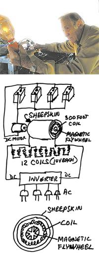
"It works this way," he said. "Static electricity is all around us, everyday. If you stick your hand in Styrofoam peanuts and pull it out, they stick. That's static electricity. My machine draws the static electricity from the air, as well as producing more. That charge then goes into a coil system that magnifies the charge and converts it into D/C power.
"That power then comes out of 12 different wires with enough amps to make electricity flow," he said.
A power converter is used to change the electricity converted from D/C power to A/C power for use in everyday needs, he said.
Operating on four car batteries, the machine works by using start-up energy from the batteries to drive a D/C motor that turns a flywheel. That magnetic flywheel runs through a system where 300 feet of 10-guage cooper wires, enclosed in sheepskin, push the electricity into 12 coils, with each coil producing somewhere around 10 volts of electricity.
"This thing will build enough electrical power to operate an automobile," he said. "It needs no gas, no oil. This one unit is more than enough to run a house."
He demonstrated his concept, by showing how his invention puts out enough power to run an outboard motor and corded work light.
While it may act as a traditional generator, Owens' invention looks nothing like one.
Sitting in the back of his old Chevy pickup, some might mistake it for a pile of rubbish, and it's a sentiment surrounding his inventions that he has seen many times in his life.
"People have always said I was crazy," he said. "I just ignore them. People said when the first computer came out the idea was crazy. Look where we are now."
Owens, an accomplished inventor, holds 27 patents for items such as farm equipment, a boat, a commode system and a newspaper rack. After working for more than 20 years as an Air Force flight engineer, Owens said the idea for his generator was always there, burning in the back of his brain, but it wasn't until an extended hospital stay that he finally made up his mind to see if it would work.
"About two years ago, I was laid up in the hospital with double pneumonia," he said. "And you know, when you're in the hospital, all you have to do is think. I decided the timing was right.
"Look at all of our men and women who have lost their lives over the battle for oil," he said. "What if we could stop our dependency on gas, oil? We could bring our guys home and go a long way in stopping pollution. I knew it would be difficult, but I had to try. This could be the turning point for our world."
Currently, Owens has completed a prototype and is looking for someone to take his invention into the marketplace.
"This thing is much bigger than me," he said. "It's going to take someone much younger than me to get this thing out in the forefront where it needs to be. I'm looking for someone to do that."