Herbert
HANSEN
Vapor Carburetor
Vapor Carburetor
http://fuel-efficient-vehicles.org/energy-news/?page_id=941
Herb Hansen – Elgin, IL – Built a vaporizing carburetion system for use with alcohol Fuel… Using 140 proof alcohol in a Ford Pinto he says he gets 70 to 75 MPG and the engine produces more power than it does on gasoline with a standard carburetor…
http://archives.chicagotribune.com/1979/08/12/page/5/article/inventors-roll-right-along-on-alcohol-water-fuel
Chicago Tribune Aug. 12, 1979
Inventors
roll right along -- on alcohol, water fuel
by Bob Wiedrich
by Bob Wiedrich
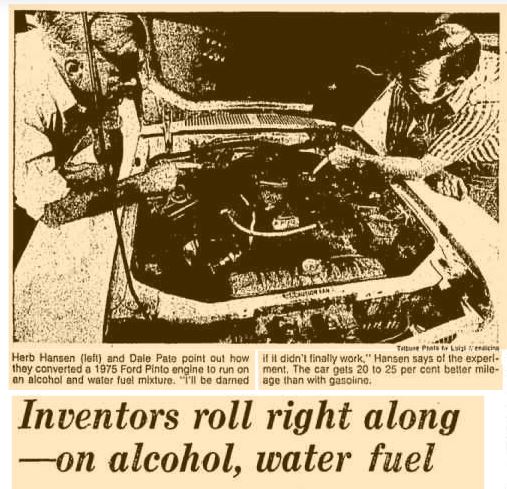
Herb Hansen (left) and Dale Pate point out how they converted a 1975 Ford Pinto engine to run on an alcohol and water fuel mixture. "I'll be darned if it didn't finally work," Hansen says of the experiment. The car gets 20 to 25 per cent better mileage than with gasoline.
Herbert Hansen and his shipmates aboard an American submarine in World War II used to sink Japanese shipping with torpedoes powered by alcohol and water.
Now. 30 years later, Hansen and his fellow Inventor, Dale Pate, use the same mixture to power a 1925 Model T-Ford and a 1075 Ford Pinto.
Both cars, although 50 years apart in sophistication and technology, run equally well on a vaporized fuel consisting of 90 per cent alcohol and 10 per cent water.
Each achieves 20 to 25 per cent better mileage on the fuel than with gasoline. Neither pollutes the environment with its exhaust. Neither suffers a loss in power or acceleration.
And between them, the two cars have rolled in excess of 1,000 trouble-free miles on the fuel mixture concocted by the two imaginative Elgin inventors.
Now, I don't know -- and neither do they -- whether their brainstorm can bail out the United States from its petroleum .
But after viewing the results of their work I'm hoping someone in Washington will look up with interest.
Because at first blush, their system works beautifully. It scoots you down the highway at the same speeds and with the same pickup you would expect from gasoline.
So even if there is some hidden flaw Hansen and Pate have yet to detect in their invention, certainly the technological geniuses of the federal government and the automotive industry should be able to solve it.
Hansen first got the idea last fall while reminiscing about the days when he and the submarine crews launched torpedoes fueled by 90 per cent alcohol and 10 per cent water. And the torpedoes shot through the water at 411 knots no hour for several miles to deliver their bulk on target.
"I figured the same idea should work with a car," Hansen said. "So Pate and I got our heads together and started experimenting. And I'll be darned if it didn't finally work."
The secret of their success is in the system they up to heat the fuel mixture to a temperature at which it would fire with maximum efficiency.
Others, they said, have experimented with straight alcohol as an lve . but with less than spectacular results. Cold alcohol just doesn't work as well. For one thing, getting started is tougher.
However, Hansen and Pate pre-heat the fuel before It is ignited in the cylinders. They also introduce water and moisturized air to further enhance efficiency.
And the real beauty of their invention is that it does not require drastically altering a car or installing an entirely new fuel system. They merely add a few mechanical gimmicks and use the same fuel tank with which the car was endowed by Detroit.
I went out to visit the two inventors in Hansen's home garage laboratory last week.
Hansen is a mechanical engineer with senior status at Means & Co. in Chicago. Pate is an Elgin police corporal in charge of that department's juvenile division.
They first met in 1966, while working as volunteers restoring aged steam locomotives at the Illinois Railway Museum in Union Illinois. So as born tinkerers, it was inevitable that they should marshal their talents.
Here is how the system works:
The alcohol-and-water blend goes from the regular fuel tank to the fuel pump. Then it passes through a pre-heater using engine coolant to heat the fuel to 170 degrees fahrenheit on its way to the carburetor.
This works best, of course, when the engine is warm. So for easy starting, on electric heater in the car does the same job the engine worms up. Starting usually requires about a 1-minute wait.
In the carburetor, the alcohol and water mix is joined by moisturized air heated by the exhaust pipe and fed from a five-gallon tank of water that is refilled with every tankful of fuel.
The moisturized air helps vaporize the fuel. And the mixture is Ignited in the cylinders, the moisture turns to super heated steam with tremendous expanding capacity to further improve power and fuel efficiency.
The Hansen-Pate system is that simple. Even I can understand It.
"The only exhaust produced is carbon and water," Hansen sid, "The some things you and I are exhaling."
The only exhaust odor is that of burned alcohol. And the inventors overcome that by sprinkling a few drops of aftershave lotion In the fuel.
"I suppose if you were driving a Cadillac, you'ld want to use Chanel No. 5 perfume instead," Pate quipped.
The Model T-Ford, the first car tested with the system, Is not equipped with fuel heaters. So it doesn't run as well.
However, the Ford Pinto has a switch on the dashboard that permits the interchange of fuels so that a driver can burn gasoline, if he chooses. The :i activates the fuel heaters when alcohol and waler are being used.
'Vehicles can run on straight alcohol, but they only get 5 to 8 miles to the gallon," Pate explained as he mixed a batch of alcohol and water in a one-ounce shotglass for a mileage test with the Pinto.
"We've gotten up to 32 miles to the gallon with two people riding in the Pinto, which has a four-cylinder, 140-cc. engine with a four-speed transmission.
"That was at 35 miles an hour. Naturally, at 55 m.p.h., you only get about 27 miles to the gallon. With an automatic transmission you'ld get about 2 miles less to the gallon ."
"You can buy alcohol in bulk for $1.27 a gallon," Hansen said.
'With 20 to 23 per cent better mileage, our fuel gets competitive with gasoline selling for $1.18 to $1.20 a gallon. And the price of gasoline is getting up there.
"Further, our fuel is a domestic source of renewable energy. You can make alcohol from organic wastes, as well as plant matter. Even garbage dumps can produce alcohol. That way, you don't have to import anything.
"We believe this Is a revolutionary idea whose time has come and that it is the only viable alternative to gasoline."
Pate and Hansen have applied for a patent. So now, all they are for is someone to come to their door with sufficient capital to bankroll their invention.
I hope the guy shows up soon.
http://www.farmshow.com/view_articles.php?a_id=822
Farm Show - Volume 5, Issue 3, 1981
100
Mpg Carburetors: Do They Really Work?
...Herb Hanson, an engineer in Elgin, Ill., has developed a preheating, vaporizing carburetor for alcohol -- the first of its kind.
"We consistently get 70 to 75 mpg in a Ford Pinto on 140-proof alcohol. The car got 32 mpg maximum on gasoline," Hanson told FARM SHOW. "There's no pollution and the car has as much or more power. We're trying to find a manufacturer right now to produce it."
Hanson's new fuel system uses both the heat of the engine and two 100-watt electric immersion heaters to vaporize alcohol before it's fed to the cylinders through a conventional propane gas regulator. The car actually starts on propane and runs on it for about 5 min. until the engine warms up.
"In converting a vehicle, we remove the carburetor, radiator, fan, and catalytic converter. The vaporizer mounts where the radiator was. Because the engine burns cooler with alcohol, you don't need that cooling system. And it burns clean enough so the catalytic converter is wasted equipment," explains Hanson.
Vapour
fuel system for an internal combustion engine.
EP0045601
EP0045601
An internal combustion engine is operated with an alcohol fuel heated by a heat exchanger and vaporized by a series of electric heating elements prior to combustion. The heat exchanger uses waste heat from the engine coolant. In addition, means for heating and humidifying the combustion air is provided to insure complete vaporization of the alcohol fuel and to overcome the lower caloric power potential of alcohol as compared to gasoline.
Background of the Invention
The present invention relates generally to an internal combustion engine operable with an alcohol fuel and, specifically, to a fuel system for supplying a vaporized fuel to the engine. The term alcohol as used herein includes a variety of hydroxyl derivatives of hydrocarbons, such as, methanol, ethanol, isopropanol, tertiary butanol and mixtures thereof with or without water.
Internal combustion engines operated with alcohol or a blended gasoline-alcohol mixture have been in use for many years. Such blending, however, lowers the boiling point of the gasoline and thereby causes vapor lock in the fuel pump at a lower temperature than would be the case with pure gasoline. In addition, the introduction of water to a blended gasoline-alcohol fuel mixture causes the mixture to separate into its constituent phases. Since the resultant fuel supplied to the carburetor is not of constant composition and does not correspond to the composition to which the carburetor was initially adjusted, the engine malfunctions.
Thus, the need exists for a fuel system which, in addition to overcoming the cold starting difficulties of an alcohol fueled engine, can operate with either gasoline, propane or alcohol.
However, another problem exists. The use of a conventional carburetor often leads to inefficient combustion with unburned fuel passing through the exhaust manifold to the atmosphere. This inefficient combustion is evidenced by an increase in hydrocarbon emissions.
As an alternative, the fuel can be injected. A fuel injected system introduces small droplets of fuel into an air stream for passage to a cylinder.
The injection inlets usually have an inside diameter of at least 0.050 inches. Although a fuel injected system is more efficient than a conventional carburetor, the injection of such large fuel droplets also results in incomplete combustion.
In an ideal fuel system, the size of each droplet would approach that of a single molecule of fuel. If each fuel molecule could be surrounded by air, complete combustion would be possible. This would result in greater engine efficiency and power output as well as the possible elimination of all emissions other than carbon dioxide and water.
By removing the carburetor and vaporizing the alcohol fuel, the present invention produces almost complete fuel combustion. In addition, any dependence on gasoline to overcome the cold starting difficulties normally associated with alcohol fueled engines is eliminated.
Summary of the Invention
The invention provides means for reducing the dependence of an internal combustion engine on hydrocarbon fuels derived from crude oil. Specifically, the present invention provides a fuel system which supplies alcohol vapors to an engine and produces nearly complete combustion.
Electrical means is provided to heat and vaporize the alcohol fuel prior to ignition and thus avoid the cold starting problems associated with the use of alcohol as fuel. In addition, means are provided to heat the alcohol prior to combustion using thermal energy generated by the engine under normal operating conditions.
The method according to the present invention comprises the steps of conveying the alcohol to a heat exchanging device in which is incorporated an electric heating element, and transferring heat from. the electric heating element or the heated engine coolant to the alcohol. The heated alcohol flows through a conduit from the heat exchanger to a vaporization chamber which contains a second electric heating element.
In the chamber the alcohol is heated to its boiling point. The alcohol vapors produced upon. boiling are then passed directly to the intake manifold of the engine. All components of the fuel system through which the heated alcohol and alcohol vapor flow are insulated to minimize heat loss.
An additional heat exchanging device located on the exhaust line heats a solution of 5-50% alcohol in water to boiling. As a result, the vapor content and temperature of the air passing to the intake manifold is increased, and steam is created to maintain the alcohol that flows from the vaporization chamber in the gaseous state.
It is an object of this invention to increase the efficiency of an alcohol operated internal combustion engine by providing means for vaporizing the alcohol fuel as well as means for heating and humidifying the air used in combustion.
It is a further object of this invention to provide a means for overcoming the cold starting problems of an internal combustion engine operated with alcohol as fuel.
Other objects and advantages will be apparent from the following detailed description made with reference to the accompanying drawings.
Brief Description of the Drawings
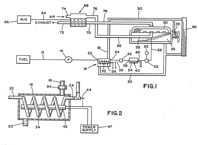
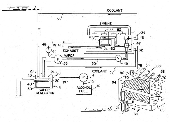
Figure 1 is a schematic representation of a preferred embodiment of the invention.
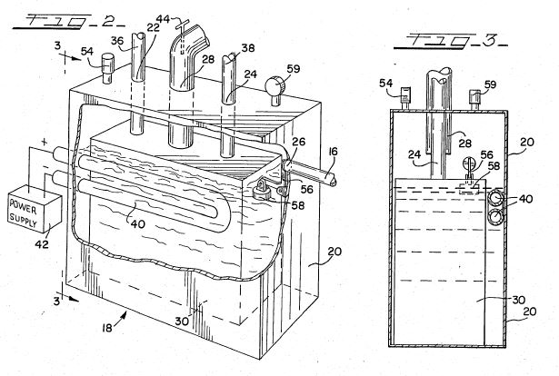
Figure 2 is a cross-sectional view of a heat exchanging device which heats the alcohol fuel with hot engine coolant.
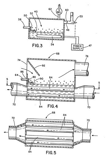
Figure 3 is a cross-sectional view of a vaporization chamber which heats and vaporizes the alcohol fuel prior to combustion.
Figure 4 is a side elevational view of an exhaust gas heat exchanging unit.
Figure 5 is a sectional view taken along the line 5-5 of Figure 4.
Detailed Description of the Invention
As illustrated in Figure 1, fuel is stored in a tank 10 and is drawn therefrom via conduit 12 under pressure produced by a fuel pump 14. The fuel may be selected from the group consisting of methanol, ethanol, isopropanol, tertiary butanol or mixtures thereof with or without water.
The alcohol fuel flows through the conduit 12 to a heat exchanger 16 at a pressure of anproxi- mately two pounds per square inch. The heat exchanger 16, best shown in Figure 2, is a hollow cylinder having a liquid coolant inlet 18 and outlet 20 plus a fuel inlet 22 and outlet 24. Liquid coolant from the internal combustion engine 26 is circulated by a water pump 28 through a hose 30 to the coolant inlet 18. The coolant circulates through the heat exchanger 16 and, via coolant outlet 20, returns to the engine 26 through a hose 32.
Fuel flows from conduit 12 to the fuel inlet 22 of the heat exchanger and through a tube 34 located within heat exchanger 16. Tube 34 is connected to the fuel outlet 24. A conduit 36 communicates the fuel outlet 24 of the heat exchanger 16 with an inlet 38 of a vaporization chamber 40.
An elongated, rod-like electric heating element 42 is located within the heat exchanger 16, tube-34 being concentrically disposed about the heating element. The electric heating element supplements the heat from the engine to overcome the cold starting difficulties associated with use of alcohol fuel. A thermostat 44 located between the heat exchanger 16 and the vaporization chamber 40 controls the electric heating element 42. Electric heating element 42 is operated by power supply 47, which may be the vehicle's battery.
The heated alcohol flows from the heat exchanger 16 through conduit 36 to the inlet 38 of the vaporization chamber 40. As illustrated in Figure 3, the vaporization chamber 40 has an outlet 48 in addition to the inlet 38. The level of fluid in the vaporization chamber 40'is regulated by a valve 50 and a float 52.
Electric heating element 54 located below the fluid level within the vaporization chamber 40 further heats the alcohol to boiling. A thermostat 53 located between the chamber 40 and the intake manifold 58 controls the electric heating element 54 and a ready light 55. The ready light indicates when the alcohol fuel is vaporized so that the engine can be started. The alcohol vapors produced flow through the outlet 48 to a conduit 56 which is connected to the intake manifold 58 of the engine 26. A butterfly valve 60 controls the volume of alcohol vapor which flows to the manifold. A safety valve 62 opens to release alcohol vapor if the pressure within the vaporization chamber 40 exceeds a predetermined value.
Referring again to Figure 1, a conduit 64 communicates a tank 66 with an exhaust gas heat exchanger 68. The alcohol-water solution contained in the tank 66 flows by gravity to the exhaust gas heat exchanger 68. The freezing of the alcohol-water solution at low temperatures is prevented by increasing the alcohol concentration within the range of 5 to 50% by volume to depress the freezing point of the solution.
As further shown in Figure 1, the exhaust gas heat exchanger 68 is a hollow cylinder comprised, in part, of exhaust gas inlet 70, exhaust gas outlet 72, air inlet 74 and air outlet 76. Exhaust gas inlet 70 is connected via exhaust pipe 78 with the exhaust manifold 80 of the engine 26. The air outlet 76 is connected via a hose 82 with the intake manifold 58 of the engine 26. Exhaust gas outlet 72 and air inlet 74 are in communication with the atmosphere.
Referring now to Figure 4, the exhaust gas inlet 70 is connected to exhaust gas outlet 72 by a plurality of heat transfer tubes, generally designated by the numeral 82. Surrounding the heat transfer tubes is a solution of 5-50% alcohol in water from tank 66. The alcohol solution enters the heat exchanger 68 through an inlet 86. The level of the fluid in heat exchanger 68 is regulated by a valve 88 and a float 90.
Hot exhaust gases are used to heat the alcohol-water solution in heat exchanger 68 to boiling. The gases are admitted at exhaust gas inlet 70, are passed through heat transfer tubes 84 and are released as cooled gases to the ambient atmosphere through exhaust gas outlet 72. Since the exhaust gases pass through a series of tubes, rather than through a single heat transfer tube, the surface area of the tubes in contact with the surrounding fluid is increased and maximum heat transfer from the gases passing through tubes 84 to the alcohol-water solution results.
Incoming air through the air inlet 74 is deflected toward the surface of the boiling solution by a baffle 92. Thereafter, the air passes over the surface of the boiling solution, absorbs moisture and passes through the air outlet 76 to flow through hose 82 to the intake manifold 58.
The operation of the invention is as follows. Thermostat 44, which controls electric heating element 42, is adjusted to a temperature slightly less than the boiling point of the alcohol use For example, the boiling point of methanol is 149'F./and that of ethanol is 173°F./ The heated alcohol flows through conduit 36 to the vaporization chamber 40. Thermostat 53, which controls electric heating element 54, is adjusted to a temperature slightly greater than the boiling point of the alcohol used. When the alcohol reaches its boiling point, the light 55 illuminates to indicate that the engine may be started.
The volume of alcohol vapor that flows from the vaporization chamber 40 and the intake manifold 58 can be manually controlled by the operator. As indicated, each thermostat is adjustable. Thus, the fuel system is capable of using alcohols with different boiling points. In addition, the system can adapt to ambient temperature changes and pressure changes due to variations in altitude. A thermostat adjustable within the range of 140.and 220°F/is suitable for this purpose.
When the engine reaches its normal operating temperature and the engine coolant is heated sufficiently, a thermostatic valve 94 opens to allow the flow of heated engine coolant from the radiator 96 through heat exchanger 16. The heated coolant supplements the electric heating element 42 to heat the alcohol fuel.
The incoming air to the carburetor used in combustion is heated and humidified in the following manner. Tank 66 gravity feeds a solution of 5-50% alcohol in water to exhaust gas heat exchanger 68.
The exhaust gases passing through exhaust pipe 78 heat the alcohol-water solution to boiling. As the incoming air passes over the boiling solution, the air is heated and becomes saturated with alcohol and water. The humidified air passes through air outlet 76 to the intake manifold 58 which is in communication with the cylinders of engine 26. The heated air aids in the vaporization of the alcohol fuel. The additional moisture creates steam in the engine cylinder which results in a higher internal pressure than in the case of a heated dry gas due to the steam:water volumetric expansion ratio of 1800:1. A dry gas, on the other hand, only expands in direct proportion to its absolute temperature.
A suitable corrosion inhibitor may be added to the fuel system to inhibit the corrosive effects of the water present. Alternatively, suitable corrosion-resistant materials may be utilized in the fabrication of the system.
As an additional advantage of the invention, greater expansive forces are realized upon combustion due to the presence of steam in the engine cylinders at elevated temperatures. The addition of water in the form of steam to the system may have the additional advantage of reducing the generation of emissions because the cooling effect of the condensed water lowers the combustion temperature thereby reducing nitrogen oxide production which is temperature- time dependent.
Vaporizer
for internal combustion steam engine
US5035227
US5035227
An alcohol/water fuel vaporizer for use in an internal combustion steam engine. The vaporizer comprises an exhaust gas chamber through which engine exhaust is passed and a vapor chamber for the generation and retention of pressurized fuel vapor. The exhaust gas chamber includes a plurality of baffles to direct the flow of the gas against a crown sheet, the latter sheet being heated thereby. The crown sheet forms the dividing partition between the vapor and exhaust gas chambers. A fuel preheater is positioned in the vapor chamber through which engine coolant is passed. A plurality of switchable fuel injectors in the vapor chamber controllably admit and spray fuel onto the preheater and crown plate in response to engine power demands and vapor chamber pressure.
BACKGROUND OF THE INVENTION
The present invention relates generally to an internal combustion steam engine that operates with an alcohol fuel and, in particular, to an alcohol/water fuel system for supplying a vaporized fuel to the engine. Upon combustion, superheated steam is generated within the cylinders to produce an elevated pressure and temperature. More specifically, the present invention pertains to a unique combination of internal combustion and external burner steam technologies particularly adapted for recirculation of heat energy to produce a highly efficient engine adapted for automotive, farm, and other uses.
The present invention is further directed to an improved vaporizer for use in connection with the above-described water/alcohol internal combustion steam engine. Such an engine was fully described in the prior U.S. Pat. No. 4,509,464 to the present inventor, Hansen. Therefore, the construction and operation of the engine itself will not be considered in detail herein except as it relates to the implementation of the present vaporizer.
Indeed, the earlier '464 Hansen patent relates to improved vaporizer technology, specifically, to a dual-chamber vaporizer construction adapted to minimize the adverse effects of fractional distillation. The vaporizer of the '464 patent has been found to perform satisfactorily for alcohol/water fuels down to about 90 proof, particularly where the fuel is of substantially pure quality, that is, uncontaminated by foreign solutes. In this connection, as water and alcohol are both excellent solvents, keeping the fuel free of solutes has proved to be a problem of non-trivial proportion.
This problem of solutes or fuel contamination has been found to be of substantial importance in connection with the commercial exploitation of internal combustion steam technology. Although high purity alcohol fuels are readily available, the cost of these fuels can range from twice to as much as ten times that of fuels produced under less exacting and controlled conditions.
The impact of the solutes problem is further accentuated when it is realized that many of the potential users of the alcohol-based internal combustion steam engine, e.g. farmers, are persons who have ample access to the recyclable waste or home-produced agricultural base stock from which alcohol may be produced. Such consumers, therefore, can be expected to manufacture fuel for their consumption as well as others in their locale. Fuels from such indigenous and varied sources characteristically contain higher impurity concentrations.
Even where uncontaminated fuel is available, the problems of fractional distillation again surface when operating with fuels of super-low proofage, i.e. generally below about 90 proof. For such fuels, the residual affinity of the alcohol molecules (for water) is insufficient `to bring` or capture the increasingly greater proportion of water molecules as the alcohol is vaporized. This problem is particularly acute at lower vaporizer temperatures which, as noted below, have been found to track reductions in alcohol concentrations.
It will be appreciated, therefore, that the improvements in vaporizer technology described herein are directed, first, to minimizing or totally eliminating the problems associated with fuel impurities and, second, to permitting the use of alcohol-based fuels of yet lower alcohol concentrations, for example 80 proof.
Importantly, and directly associated with obtaining this latter objective, the present invention results in yet another improvement in the overall efficiency of the internal combustion steam engine. Efficiencies of approximately 60 percent are now obtainable which, in turn, result in typical fuel economies of between 20 and 40 miles per gallon of 80 proof alcohol-based fuel--such fuel being obtainable for as little as ten cents per gallon.
The internal combustion steam engine described in the Hansen '464 patent requires no radiator as the waste heat collected in the engine's liquid cooling system is routed to the fuel vaporizer where it is converted into useful energy in the processes of vaporizing the alcohol based fuel. In this manner, one significant source of engine inefficiency, the dissipation of engine heat by the radiator, has been largely eliminated.
The Hansen '464 engine also reduced a second major source of engine inefficiency by converting the otherwise wasted exhaust gas heat energy into useful work by preheating the incoming carburetor combustion air.
As noted, certain difficulties were experienced with the engine configuration of Hansen '464 as the proofage of the fuel was reduced, that is, as the ratio of water to alcohol was increased. More specifically, it has been found that the amount of waste engine heat available in the cooling system generally decreases as the fuel proofage is reduced.
Coupled with this reduced waste heat generation is the counterproductive requirement that the fuel itself requires more heat energy to vaporize at these higher water concentrations--this by reason that water requires more energy per pound to vaporize than, for example, ethanol. Thus, even with the improved two-chamber vaporizer described in Hansen '464, fractional distillation was again found to be a problem for alcohol fuels of very low proofage.
With respect to the second source of waste engine heat discussed above, it was discovered that the exhaust gas heat energy actually increases as the fuel proofage is lowered due, principally, to the increased steam content of the engine exhaust. The available exhaust gas heat energy significantly exceeds the combustion air preheat requirement.
Unlike the vaporizer of Hansen '464, the present vaporizer has been substantially reconfigured to facilitate collection and conversion of waste heat energy from both the engine coolant and exhaust systems. In this manner the unused exhaust heat energy is meaningfully recycled thereby correcting inadequacies in vaporizer operation at lower proofages while, importantly, raising the overall efficiency of engine operation.
The vaporizer preferably defines a generally enclosed rectangular volume having a form-factor adapted to fit into, and replace, the radiator of a conventional internal combustion gas engine. More specifically, the vaporizer comprises respective air-tight `exhaust gas` and `vapor` compartments and chambers vertically separated by a `crown sheet` barrier. The lower or exhaust gas chamber has inlet/outlet ports at opposed ends thereof and interior baffles whereby the flow of exhaust gas is routed through this lower chamber in proximity to the crown sheet--such sheet defining a shared common wall between the two chambers.
Particularly significant to the performance of the present vaporizer (especially where low proofage and contaminated fuels are used) is its efficacious utilization of the excess exhaust gas energy. These exhaust gases are employed, not merely as a supplemental source of heat energy, but as an energy source at substantially greater temperature, typically between 500 DEG-600 DEG F., than available using the engine coolant approach of Hansen '464.
The vaporizer crown sheet is heated by passage of the exhaust gases to substantially the temperature of the gas itself. As discussed in more detail hereinafter, vaporization is achieved herein by spraying liquid fuel onto the crown sheet which, as noted, has been raised to a temperature several hundred degrees above the vaporization temperature of either water or alcohol (ethanol). It will be appreciated, therefore, that the fuel instantaneously vaporizes upon contacting the crown sheet without regard to the proofage or solutes contained therein.
The upper vaporization region of the Hansen '464 vaporizer, by contrast, receives the engine coolant at its hottest temperature, typically 260 DEG F.--well above the 212 DEG F. vaporization temperature of the hardest-to-vaporize fuel constituent, water. For this reason, the Hansen '464 vaporizer operated well.
Problems with this prior art vaporizer, however, are found where engine operations are attempted with alcohol fuel concentrations below about 90 proof. As previously noted, such operation is associated with a corresponding reduction in the available coolant system heat energy resulting, in turn, in lowered coolant temperatures. As coolant temperatures approach the vaporization temperature of water, fractional distillation is again seen.
The present vaporizer does not, however, sacrifice the efficiency advantages achieved through the recycling of waste engine heat. In conformity with the teachings of Hansen '464, no radiator is employed. Instead, a network of copper tubes defining a fuel preheating heat exchanger is positioned in the vapor chamber above the crown sheet through which the engine coolant is passed. Fuel is sprayed onto this heat exchanger which, in turn, lowers the coolant temperature and heats and/or vaporizes the fuel. The unvaporized fuel thereafter contacts the crown sheet where complete vaporization is assured.
A further advantage of the present vaporizer relates to its ability to handle the wide fuel vaporization demands associated with corresponding engine load changes. It will be appreciated that substantially greater vaporization is required for high vehicle speeds or uphill travel as compared with idle or low speed operations.
Accommodation of these ranging load demands is achieved through the use of a plurality of spray nozzles or injectors in the vapor chamber, each injector being gated-on in response to predetermined vapor chamber pressures. Two injectors have been found to be sufficient for most applications.
Thus, at vapor pressures in excess of about 3.5 psi all fuel spray injectors are off--the engine is operating from the residual volume of pressured fuel vapor in the vapor chamber and from any vapor being generated by the engine coolant heat exchanger. As the vapor pressure drops below about 2.5 psi, the first vapor spray injector is enabled. This injector, be placed in proximity to the hottest region of the crown sheet, ordinarily provides sufficient fuel vapor for continuing normal cruise vehicle operations. In fact, excess vaporization ordinarily will occur with this single injector resulting in the periodic shutting-off of the injector as, again, pressures in excess of 3.5 psi are achieved.
At ever increasing engine/vehicle loads, the proportion of time that the injector is "on" increases until the point is reached where the injector must remain "on" continuously to maintain sufficient operational vapor pressure. Under extreme load conditions, the vapor pressure may continue to decrease, notwithstanding that this first injector remains on continuously, thereby necessitating use of the second or auxiliary spray injector. This injector, like the first injector, is pressure controlled, being enabled when vapor chamber pressures drop below about 1.5 psi.
Advantageously the exhaust heat energy available to the vaporizer increases with increasing engine power loads thereby providing the necessary energy to vaporize the correspondingly increased fuel requirements. Crown plate temperatures remain relatively constant with changing engine loads. As a consequence, highly efficient vaporization is realized under all load conditions.
And yet a further feature of the present vaporizer relates to the highly effective sound muffling characteristics associated with engine combustion. More specifically, the exhaust gas emitted by the present engine, particularly where low proofage fuel is used (e.g. 80 proof) contains a substantial percentage of superheated steam (e.g. 40%) at temperatures of between 500 DEG-600 DEG F. As the exhaust gas passes through the vaporizer, it is significantly cooled--exiting the vaporizer at temperatures around 200 DEG F. This cooling results in significant condensation and a corresponding drop in pressure.
As a consequence, "noise" pressure waves are substantially attenuated as the exhaust transits the vapor chamber thereby eliminating or significantly reducing the need for a separate noise reduction system. And due to the inherently pure, nonpolluting character of the internal combustion steam engine, mufflers and catalytic converters may be entirely avoided.
From the foregoing it will be appreciated that the vaporizer of the present invention exhibits startling improvements in a number of important categories critical to internal combustion steam engine operation. These improvements include full and complete vaporization, i.e. the elimination of fractional distillation, under widely varying engine load conditions and where impure and low proofage fuels are employed; the increase in engine efficiency by more effectively recycling engine waste energies; the elimination or reduction in the requirement for engine muffler systems; and control over the quantity of vapor production under extreme load variations.
BRIEF DESCRIPTION OF THE DRAWINGS
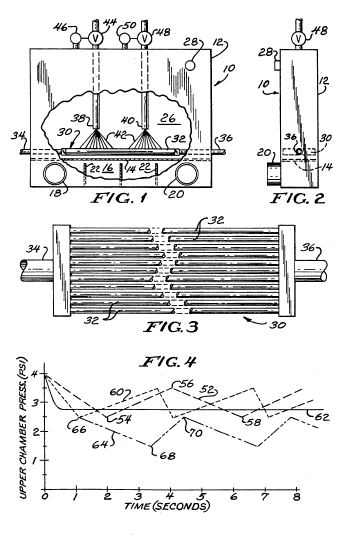
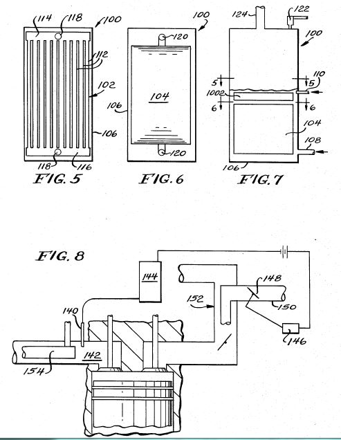
FIG. 1 is a front elevation view of the present vaporizer with portions broken away to reveal interior details thereof;
FIG. 2 is a right side elevation view of the vaporizer of FIG. 1;
FIG. 3 is a top plan view of the fuel preheater of the present vaporizer; and,
FIG. 4 is a graphic representation of the vapor chamber fuel vapor pressure of the present vaporizer as a function of time for several engine load conditions.
DESCRIPTION OF THE PREFERRED EMBODIMENT
Referring to FIGS. 1 and 2, the vaporizer 10 of the present invention comprises an outer housing 12 preferably of an overall size configuration to facilitate placement in the engine compartment in the space otherwise generally occupied by the radiator of a conventional automobile.
In this connection it should be understood that the internal combustion steam engine, for example as described by Hansen in U.S. Pat. No. 4,509,464, may advantageously be constructed using conventional internal combustion gas engine blocks and cylinder/piston assemblies or alternatively, simply by converting the fuel, cooling, and exhaust systems of such readily available engines. Thus, the engine technology of the present application, and in particular the vaporizer described herein, finds significant if not principal application in the conversion of existing gas engine vehicles.
It is for this reason that the present vaporizer 10 is preferably configured in size to replace conventional radiators. It will be understood, however, that alternative vaporizer configurations are contemplated.
Referring again to FIGS. 1 and 2, housing 12 defines a pair of pressure-tight chambers separated by, and sharing a common dividing wall, referred to herein as crown sheet 14. The lower or exhaust gas chamber 16 extends along the full bottom width of the vaporizer and has an exhaust gas inlet 18 and outlet 20 spaced at respective opposed ends thereof. Engine exhaust is routed through the carburetor (not shown) to heat the incoming combustion air (as described in Hansen '464), thereafter to vaporizer inlet 18, through chamber 16 and outlet 18, in turn, being expelled to the ambient air through a conventional exhaust pipe (not shown).
More than sufficient energy is available from the engine exhaust, even after heating the incoming combustion air, to aid in the proper vaporization of the alcohol-based fuel. This is particularly true in connection with engines operated from low proofage alcohol fuels, e.g. below about 90 proof, where the superheated steam content of the exhaust, with its corresponding latent heat energy, is high. Indeed, exhaust gas temperatures at the inlet 18 of the vaporizer are typically in the order of between 500 DEG and 600 DEG F.
One or more baffles 22 are placed transversely across the exhaust gas chamber to create exhaust gas turbulence and to force the exhaust gas into proximity with the crown sheet 14 (transverse being defined relative to the path of exhaust gas flow therein, i.e. transverse to the path from inlet 18 to outlet 20). The baffles defines apertures 24 along the upper ends thereof forcing the exhaust gas to transit through the chamber in close proximity to the crown sheet. In this manner the proper transfer of heat energy from the exhaust gas to the crown sheet may be assured.
In one embodiment of the vaporizer the exhaust chamber is approximately 22" in length, 2" in height, and 4" in width, with respective exhaust gas inlets/outlets 16,18 spaced approximately 16" apart. The baffle apertures 24 are 1/4" high and, as noted, extend along the entire chamber width.
Due to this close association or passage of the exhaust gas to the crown sheet, the crown sheet is heated substantially to the temperature of the exhaust gas, that is, to about 500 DEG-600 DEG F. in the region of inlet 18. As the exhaust passes through chamber 16, however, heat energy is extracted from the exhaust gas, being absorbed by the crown sheet, thereby resulting in the lowering of the exhaust gas temperature as it passes through this chamber. Exhaust gas temperatures as low as 200 DEG F. may be seen at outlet 18. The temperature of the crown sheet 14 exhibits a corresponding decrease in temperature along its length.
The interior of outer vaporizer housing 12 above the crown sheet defines a vapor chamber 26. Vaporized alcohol/water fuel is maintained, as set forth hereinafter, at a pressure of between about 1 and 5 psi within the vapor chamber and supplied to the carburetor (not shown) according to the power demands placed on the engine. Vapor chamber outlet 28 interconnects to the vapor fuel inlet of the carburetor
As best illustrated in FIG. 3, a fuel preheater 30 is positioned in the lower portion of the vapor chamber generally adjacent to the crown sheet, but spaced therefrom a sufficient distance (i.e. about 1/8 inch) to minimize or preclude conductive heating of the preheater 30 by the exhaust-heated crown sheet.
Preheater 30 includes a plurality of spaced, generally parallel, copper tubes 32 extending lengthwise along the vaporizer, each tube being in fluid communication at its respective distal ends with a cooling fluid inlet 34 and outlet 36. In the fuel preheater illustrated in FIG. 3, copper tubes of 1/4" diameter are spaced approximately 1/16" apart across substantially the full 4" vaporizer width.
Coolant from the conventional engine liquid cooling system is routed to vaporizer preheater inlet 34, through the plural copper tubes therein, in turn, returned to the engine through outlet 36. In the preferred arrangement, fuel preheater 30 functions not merely in its fuel preheating capacity, but as a replacement for the conventional engine coolant radiator.
Fuel is introduced into vaporizer 10 through one or more spray nozzles or fuel injectors. It has been found that two injectors are generally sufficient to accommodate the varying loads encountered by most engine-driven vehicles. It will be appreciated, however, that single injector vaporizers, or vaporizers employing more than two injectors are contemplated herein.
Thus, the vaporizer of FIGS. 1 and 2 illustrates the use of two injectors. The first or primary injector 38 is positioned in closest proximity to the exhaust gas inlet 18. In this manner the fuel from this injector is exposed to the hottest regions of both the preheater 30 and crown plate 14 thereby assuring the maximum vaporization effectiveness with respect thereto. A second or auxiliary injector 40 is positioned along the preheater/crown sheet generally adjacent to primary injector 38.
More specifically, both injectors are oriented above preheater 30 such that the respective sprays therefrom define generally circular patterns of about 4" diameter. In this manner fuel is directed across the full corresponding width of preheater 30. Primary injector 38 may be located inwardly from exhaust gas inlet 18 approximately 5" to assure exposure of the fuel therefrom to the hottest regions of the preheater and crown sheet. The auxiliary injector 40 is preferably positioned 6" closer to exhaust gas outlet 20 such that the spray therefrom contacts a virgin region of the preheater/crown sheet, that is, so the respective spray patterns do not overlap.
As best shown in FIG. 1, the spray from the respective injectors 38,40 is directed downwardly against the copper tubes 32 of preheater 30. This spray or fuel mist 42 acts, by reason of its ambient, i.e. intrinsically cool, temperature, to correspondingly lower the temperature of the engine coolant passing through preheater 30--the engine coolant typically entering the preheater at temperatures well-above ambient, often in the order of 250 DEG F. It will be understood that this exchange of otherwise wasted engine heat energy serves, not merely to maintain proper engine operating temperatures, but as a mechanism to raise the temperature of the incoming combustion fuel mixture.
The energy content and absolute temperature of the engine coolant entering the vaporizer may be insufficient to vaporize the required combustion fuel, and to do so without fractional distillation, the latter resulting in excessively rich vapor concentrations followed by the inevitably lean fuel mixtures associated with the premature vaporization of the alcohol constituent. As noted, these difficulties become more debilitating where low proofage or contaminated fuels are used.
The present vaporizer solves this energy shortfall by efficaciously converting excess exhaust gas energy to the vaporization task. This use of a second source of energy is extremely important as, at lower fuel proofages, the margin of available exhaust gas energy, over that required to heat the incoming combustion air, is increasing.
In short, a significant by-product of the internal combustion steam engine would be expelled as waste heat but for the innovations herein disclosed. The tapping of this heretofore unused energy source translates and corresponds directly to improved engine efficiencies--efficiencies which now render the present alcohol-based engine competitive, on a miles per fuel gallon basis, with the higher specific heat (per volume) hydrocarbon fuels, i.e. gasoline.
In addition to this increase in engine efficiency afforded by the present invention is the, possibly more subtle but equally significant, improvement in vaporizer efficacy occasioned by utilization of the exhaust gas energy source--a source available at substantially elevated temperatures, generally in the order between 500 DEG-600 DEG F.
Referring again to FIG. 1, it will be seen that the fuel mist 42 from injectors 38,40 is sprayed either directly onto the crown sheet 14 or indirectly thereon after first contacting and preheater 30. The advantage of this arrangement is that all fuel, regardless of the water concentration or its solute content, immediately flashes into the vapor state upon contact with the superheated crown sheet.
Fuel to each of the injectors 38,40 is independently controlled, i.e. turned "on" or "off", by individual valves that are separately and electrically actuated in response to the sensed pressure within the vapor chamber 26. Specifically, primary valve 44 is positioned in the primary injector 38 fuel supply line and is actuated by switch 46. Switch 46 is mounted to and extends through the vaporizer housing and is responsive to pressure changes within the vapor chamber. Switch 46 is selected to enable valve 44, i.e. to turn-on the spray of fuel from primary injector 38, when the vapor chamber pressure falls below about 2.5 psi and to turn such injector "off" when the pressure therein exceeds about 3.5 psi.
Similarly fuel to the auxiliary injector 40 is controlled by an auxiliary valve 48 and pressure switch 50 combination. The pressure settings of switch 50, however, are set to trigger auxiliary injector operation only when vapor chamber pressures drop below normal operational levels. Thus, the auxiliary injector spray will be triggered should vapor chamber pressures fall below about 1.5 psi and this spray will remain "on" until chamber pressures recover to about 2.5 psi.
FIG. 4 is illustrative of vaporizer operation, specifically the fuel vapor pressure within the vapor chamber 26, under varying vehicle/engine load conditions. Referring first to the solid trace line 52, there is depicted typical fuel vapor pressures where the vehicle is operated under a "low cruise" condition, that is, at a constant low to moderate speed, on level terrain.
For purposes of illustration, each of the operational curves of FIG. 4 assumes an initial vapor chamber pressure of 4 psi. Such increased chamber pressures would not be unanticipated under certain operating conditions, for example, where the engine has been reduced to idle following a period of higher power operation.
At time "zero", the high vaporizer pressure results in both injectors being disabled, i.e. turned "off", such that no additional fuel is being admitted to the vapor chamber. Under sustained low-cruise power settings (again, as shown by trace 52), the residual vaporized fuel within the vapor chamber is adequate to sustain engine operation for a short duration, e.g. 1-2 seconds, without the introduction of additional fuel into the chamber. The vapor pressure, however, drops steadily until the 2.5 psi trigger threshold, at 54, of the primary pressure switch 46 is reached.
At this instant, fuel from injector 38 is sprayed onto both the preheater 30 and crown sheet 14 in the respective hottest regions thereof. In the case of the crown sheet, temperatures of 500 DEG-600 DEG F. are not uncommon. As a consequence, complete and instantaneous vaporization of that fuel is achieved.
The volume of fuel entering the vaporizer through injector 38, coupled with the heat capacity of the vaporizer, produces more vaporized fuel than is demanded by the engine carburetor (not shown) during low-cruise vehicle operations. Thus, the excess vaporized fuel results in increasing vapor chamber pressures which continue to climb until the 3.5 psi turn-off threshold of switch 46 is reached, shown at 56. At this juncture, the primary injector is switched off and, as no fuel is being injected into the vapor chamber, the vapor pressure declines until the pressure again reaches the 2.5 psi trigger pressure of switch 46, shown at 58. The primary injector 38 is thusly cycled to produce and maintain the required vapor production.
It will be observed that, during operation at the abovedescribed low-cruise power level, vapor chamber pressures remain constantly above the 1.5 psi trigger threshold of the auxiliary injector switch 50 and, consequently, operation at these lower power levels may be sustained without actuation of such auxiliary injector.
The dotted line trace 60 of FIG. 4 similarly illustrates vehicle operation, but under somewhat greater engine power demands, for example, under sustained high-cruise level terrain vehicle travel. Under such conditions, the consumption of fuel vapor increases resulting in the correspondingly sharper negative slope of the depicted vapor pressure curve during periods where fuel injector 38 is off, and, less rapid recoveries of vapor chamber pressuring during injector "on" periods.
It will be understood that by continuing to increase the engine power level, with its corresponding increased fuel vapor requirement, a point of equilibrium may be reached where the production of vaporized fuel from the primary injector 38, alone, is just sufficient to meet engine fuel demands. This condition is shown by line trace 62 of FIG. 4.
If the engine power requirements are increased beyond this level, for example for extreme vehicle speeds, for towing heavy loads, or for steep up-grade travel, fuel vapor production from the single injector 38 may be insufficient. As shown by the line trace 64, vapor chamber pressure, under such extreme load conditions, continues to decrease even following actuation of the primary injector 38 which occurs, shown at 66, when the pressure drops to 2.5 psi. Actuation of the primary injector slows the rate of vapor pressure loss but, as noted, does not arrest its downward trend.
As the vapor chamber pressure continues to drop, the 1.5 psi trigger threshold of auxiliary pressure switch 50 is reached, at 68, which, in turn, enables the corresponding auxiliary injector 40. The vapor generated by these combined injectors is sufficient to provide the vaporized fuel requirements of the engine even when operated under sustained full power conditions. Thus, vapor chamber pressure increases until the 2.5 psi shut-down threshold of the auxiliary switch is reached, at 70. Upon the closing of auxiliary valve 48, chamber pressure again declines. Full or high engine power operations are, therefore maintained in this manner by cycling the auxiliary injector 40 while the primary injector 38 remains continuously enabled.
It will be appreciated that the use of multiple injectors and the use of injectors having fully controllable duty cycles provides a vaporizer having enhanced flexibility to handle the widely varying engine load requirements, from idle to full power. Furthermore, employment of the engine coolant fuel preheater provides an effective means for maintaining proper engine operating temperatures while simultaneously facilitating the recovery of otherwise lost engine heat energy. This energy source, coupled with the incorporation of an exhaust gas chamber, with its high capacity, temperature heat exchange capability, further contributes to the present invention, its improved vaporization consistency in the face of varying quality and proofage fuels, and its complementary attributes contributing to overall high engine fuel efficiencies
A further contribution of the present vaporizer pertains to its intrinsic noise attenuating capacity. Passage of the exhaust gas, which gas contains a high content of superheated steam, through the exhaust gas chamber results in the effective attenuation of a large proportion of the ordinary engine combustion noise. Use of the present vaporizer, therefore, obviates the requirement for any further muffling system in most ordinary vehicular applications.
High
efficiency internal combustion steam engine
US4509464
US4509464
An internal combustion steam engine is operated with an alcohol-water fuel mixture vaporized prior to combustion by heated engine coolant that flows through a first heat exchanger. The first heat exchanger or vapor generator uses the waste heat from the engine coolant to heat and vaporize the alcohol-water mixture. A second heat exchanger using exhaust gases heats the combustion air before passage through the intake manifold. Complete vaporization of the alcohol fuel is accomplished to overcome the lower caloric power potential of alcohol as compared to gasoline and to insure complete and regular combustion.
BACKGROUND OF THE INVENTION
The present invention relates generally to an internal combustion steam engine that operates with an alcohol fuel and, in particular, to an alcohol-water fuel system for supplying a vaporizing fuel to the engine. Upon combustion, superheated steam is generated within the cylinders to produce an elevated pressure and temperature. More specifically, the present invention pertains to a unique combination of internal combustion and external burner steam technologies particularly adapted for the recirculation of heat energy to produce a highly efficient engine adapted for automotive and other uses.
Conventional gasoline engines operate on what is known as the OTTO cycle wherein a carbureted mixture of fuel and air is ignited following compression in the well known manner and, thereafter, expelled to the surroundings through an exhaust manifold and muffler system. Such engines, however, exhibit substantial losses of heat and other energy which, in turn, results in poor fuel to mechanical work energy conversion. First, the burning gases produce a mean effective pressure in the cylinder of about 100-200 psi but at an extremely elevated temperature of typically 3000 DEG F. This excessive heat, which is generally dissipated through an engine radiator to avoid cylinder and piston destruction, accounts for an approximate 35 percent loss in the BTU energy of unburned gasoline fuel.
Further, it is known that proper stoichiometric mixtures for complete fuel burning do not ignite readily and, therefore, excessive fuel (i.e. rich mixture) is generally provided. This, in turn, results in partial or unburned carbon exhaust products contributing to environmental pollution and further losses in efficiency. As an alternative, conventional fuel injection systems may be employed to directly inject fuel droplets into the airstream. Although more efficient than conventional carburetors, the injection of relatively large droplets, typically 0.050 inches in diameter, still results in incomplete combustion.
In addition to the above described unburned fuel and coolant energy losses, the exhaust gases are quite hot, often in excess of 1500 DEG F., thereby adding further to the heat energy loss. Indeed, it is common to see exhaust manifolds heated to glowing, and flames emitted from the exhaust pipe are not uncommon. In total, these exhaust related losses account for another 35 percent of the total gasoline fuel energy. Deducting yet another 10 percent for frictional losses, the overall efficiency of a typical internal combustion gasoline engine is in the order of about 20 percent.
In sharp contrast to the elevated operating temperatures of gasoline fueled internal combustion engines, a typical external combustion steam engine operates at temperatures between about 440 DEG F. and 470 DEG F. corresponding to steam pressures between about 400 psi and 500 psi. Thus, a conventional external combustion steam engine produces the requisite cylinder pressure but at a greatly reduced operating temperature which, in turn, significantly lessens engine cooling and exhaust heat losses.
Conventional external combustion steam engines, however, have several dissadvantages which render them unsuitable for use in modern automobiles. First, a relatively bulky boiler is required to generate the steam. In addition, significant time is required to heat the boiler to operating pressures which delays productive use of the engine upon initial start-up and, during low load periods, renders the system relatively more inefficient.
Conventional external combustion steam engines are, in any event, rather inefficient. These engines, which operate on the RANKINE cycle, require the burning of fuel to heat and vaporize water contained within a boiler. The resulting steam passes through necessary piping and controls and, in turn, is admitted to engine cylinder. Assuming that the boiler water is initially at 32 DEG F., 180 BTU per pound must be added to raise the water to the 212 DEG F. boiling point and an additional 1030 BTU to convert the water to the steam phase at 500 psi. Assuming, further, that a typical steam engine exhausts the steam at as little as 20 psi, an overall engine efficiency of 4 percent results. Even this low efficiency figure is optimistic as other losses including boiler efficiency were not considered.
The present internal combustion steam engine, by contrast, represents a highly efficient combination of steam and internal combustion technologies particularly suited to the reclamation of otherwise lost heat energies. First, the energy in the engine cooling system is recycled to vaporize the water-alcohol fuel mixture. This vaporized fuel burns more rapidly thereby producing the maximum pressure in the cylinder and the highest mean effective pressure. The water enters the cylinder as a vapor with an enthalpy already at 1150 BTU per pound requiring only an additional 50 BTU to raise its pressure, as in the steam engine example above, to 500 psi. Assuming, again, an exhaust pressure of 20 psi and substantially complete recirculation of the coolant energy (actually, a few percent recirculation loss is typical), a thermal efficiency of about 88 percent results.
Further, since substantially all the fuel of the present invention is burned, there is correspondingly little lost fuel energy and minimal environmental pollution. To further improve the efficiency of the present engine, the exhaust gases may advantageously be recirculated to preheat the carburetor inlet air to approximately 500 DEG F. thereby further reducing the heat which must be subsequently added or generated in the steam combustion cylinder cycle. In this manner, the exhaust losses are reduced to about 15 percent. Considering frictional losses, an overall efficiency of slightly more than 50 percent may be achieved. This is about three times the efficiency of a conventional gasoline internal combustion engine, about twice that of a diesel, and over ten times as efficient as a steam engine.
A further advantage of the present engine is that it may be operated with many differing fuels including most alcohols. This includes a variety of hydroxyl derivatives of hydrocarbons such as methanol, ethanol, isopropanol, tertiary butanol and mixtures thereof with water. The preferred fuel is ethanol which can advantageously be made inexpensively from organic waste. In addition, ethanol will support combustion when mixed with water even at low concentrations. This heat of combustion turns the water into, or superheats, the steam.
Internal combustion engines operated with alcohol or a blended gasoline-alcohol mixture are well known. Such blending, however, lowers the boiling point of the gasoline and thereby causes vapor lock in the fuel pump at a lower temperature than would be the case with pure gasoline. In addition, the introduction of water to a blended gasoline-alcohol fuel mixture causes the mixture to separate into its constituent phases. Since the resultant fuel supplied to the carburetor is not of constant composition and does not correspond to the composition to which the carburetor was initially adjusted, the engine malfunctions.
SUMMARY OF THE INVENTION
According to the present invention, an alcohol-water fuel is pumped from a fuel reservoir into a first heat exchanger or vapor generator where the waste heat from the engine cooling system vaporizes the fuel. The fuel then passes through suitable valves, controls and a vapor carburetor before entering the engine cylinders. The alcohol burns in the cylinders turning the water vapor into superheated steam. A high alcohol content results in high pressure and temperature. The reverse is also true. Alcohol of 125 to 140 proof gives engine performance superior to gasoline fuel with lower proofages, down to about 90 proof, performing quite substantially. A higher proof alcohol is needed in cold weather when the passenger compartment of the vehicle must be heated, because engine heat losses are greater in cold weather.
In one embodiment of the present invention, an electrical means is provided in a first heat exchanger to heat and vaporize the alcohol fuel prior to ignition and thus avoid the cold starting problems associated with the use of alcohol as fuel. According to a second embodiment, warmed engine coolant is circulated through the first exchanger similarly vaporizing the alcohol fuel. The unique two-stage heat exchanger, having an upper first stage hot plate, is particularly suited to the vaporization of low proofage fuels while minimizing fractional distillation. In addition, means are provided to heat the combustion air in a second heat exchanger priot to combustion using thermal energy of the hot exhaust gases generated by the engine under normal operating conditions.
According to the present invention, the alcohol-water mixture is conveyed to the first heat exchanger, and heat is transferred from the electric heating element or the heated engine coolant to the water-alcohol. In the first heat exchanger the alcohol-water fuel is vaporized. The alcohol and water vapors produced are then passed to the intake manifold of the engine. All components of the fuel system through which the heated fuel and the vapors flow are insulated to minimize heat loss.
A second heat exchanger located on the exhaust lines heats the combustion air which also flows to the intake manifold. As a result, the temperature of the air passing to the intake manifold is increased, and the vapors generated in the first heat exchanger are maintained in a gaseous state prior to combustion.
It is an object of this invention to increase the efficiency of an alcohol operated internal combustion engine by providing means for vaporizing an alcohol-water fuel and means for heating and humidifying the air used in combustion.
It is a further object of this invention to provide a means for overcoming the cold starting problem of an internal combustion engine operated with alcohol as fuel.
Other objects and advantages will be apparent from the following detailed description made with reference to the accompanying drawings.
BRIEF DESCRIPTION OF THE DRAWINGS
FIG. 1 is a schematic representation of a preferred embodiment of the invention;
FIG. 2 is a cutaway perspective view of a first heat exchanger or vapor generator which heats and vaporizes the alcohol water mixture with hot engine coolant;
FIG. 3 is a sectional view taken along line 3--3 of FIG. 2; and
FIG. 4 is a cutaway perspective view of the second heat exchanger which heats the combustion air with exhaust gases.
FIG. 5 is a sectional view of an alternative embodiment of the present vapor generator taken substantially along line 5--5 of FIG. 7 depicting the vaporizer hot plate;
FIG. 6 is a section view of the vapor generator of FIG. 5 taken substantially along line 6--6 of FIG. 7 depicting the vaporizer heat exchanger;
FIG. 7 is a profile view of the vapor generator of FIG. 5 with portions broken away to reveal the positioning of the hot plate and heat exchanger therein; and,
FIG. 8 is functional block representation of the oxygen sensing carburetor control of the present invention.
DETAILED DESCRIPTION OF THE INVENTION
Referring to FIG. 1, the fuel is stored in a reservoir 10 and is withdrawn therefrom through a conduit 12 under pressure produced by a fuel pump 14. As previously described, the fuel is an alcohol-water mixture, the preferred alcohol being ethanol.
The fuel flows through a conduit 16 to a vapor generator 18, which is essentially a heat exchanger, at a pressure of approximately two pounds per square inch. The vapor generator 18, more clearly shown in FIGS. 2 and 3, is a hollow container or cylinder 20 having a liquid coolant inlet 22 and outlet 24 in addition to a fuel inlet 26 and outlet 28.
Positioned within the container 20 is a heater core 30 through which engine coolant can circulate. Specifically, liquid coolant from the internal combustion engine 32 is circulated by a water pump 34 through a hose 36 to the coolant inlet 22. The coolant then circulates through the heater core 30 and, after passing through the coolant outlet 24, returns to the engine 32 through a hose 38.
An elongated, rod-like electric heating element 40 is located within the continer 20, the heating element 40 being immersed within the fuel which surrounds the heater core 30. The electric heating element 40, which is operated by a power supply 42 (for example, the vehicle's battery), supplements the heat from the engine coolant to overcome the cold starting difficulties associated with the use of alcohol fuel. A thermostat 44 positioned between the vapor generator 18 and the vapor carburetor 47 of the engine controls the heating element 40 and a ready light 48, which indicates that the circuit is operating. The alcohol and water vapors flow through the fuel outlet 28 to a conduit 50 in communication with a demand valve 49 connected to the vapor carburetor 47. The carburetor 47, in turn, is connected to the intake manifold 46 of the engine.
A pressure relief valve 54 which is set, for example, at four pounds pressure can be used as a safety device to prevent the buildup of excess pressure within the container 20. The liquid fuel level in the container 20 is regulated by a valve 56 and a float 58 associated with the fuel inlet 26.
In operation, the fuel pump 14 fills the vapor generator 18 with fuel to a level about one inch below the top of the heater core 30. This serves the purpose superheating the vapor and channeling all the liquid to be vaporized by the submerged heating element 40. With alcohol proofage at 140 or below there is a tendency for fractional distillation to occur when the engine coolant is being heated to the operating temperature. As the temperature passes 175 DEG F., the alcohol would be distilled leaving the water behind. This can create an imbalance in the air-fuel ratio. Later as the engine reaches operating temperature, the remaining water would be vaporized. Thus, the vapor would first be too rich and then too lean. The heating element 40 and the channeling of the liquid along the sides of the heater core 30 solves this problem.
A pressure relief valve such as valve 54, is required by law on all pressure vessels. It can be connected to a hose (not shown) to vent back to the fuel reservoir so no fuel is lost and most of the heat is recovered. Normally the valve will not be used. If the valve should start venting, it indicates too high a proofage of fuel is used. Lower proofage produces a lower operating temperature.
The heating element 40 activated by a pressure switch 59 is on when the pressure within the container 20 is less than three pounds per square inch. Thus, the heating element operates when starting from a cold start. In severely cold weather, when heat is needed for the car and heat loss is substantial, the heating element will operate continuously.
In practice, the heat of combustion produced as the ethanol water fuel is burned raises the temperature and pressure of the vapor from 212 DEG F. and 14.7 psi to superheated steam at 500 psi and 600 DEG F. by only adding 148 btu per pound of vapor. If the typical boiler arrangement is used, 1270 btu would be required. The expanding steam moves the piston to produce useful work. In a preferred embodiment exhaust gas temperature and pressure are 280 DEG F. and 50 psi, respectively, with a heat content or enthalpy of 1174 btu.
The flash point of ethanol is 70 DEG F. This means that ethanol will not ignite at a temperature less than 70 DEG F. This is a safety feature in the event of an accident. The flash points, however, also present a problem in ignition because most of the time the ambient temperature of the fuel mixture is below the flash point. By vaporizing the fuel, the ignition problem is solved except for the fact that if the engine is cold, the vapor will cool and condense below the flash point.
As a solution to that problem, propane can be used as a starting fuel. A small tank (not shown) with a pressure reducing valve and a vaporizing valve furnishes propane vapor to the vapor generator at one pound pressure. As long as the alcohol-water vapor pressure is less than one pound, the propane is admitted. When the pressure rises above that, the propane will no longer flow. By this time, however, the engine is at operating temperature, and the carburetor air is above the minimum of 212 DEG F.
Propane was selected as the auxiliary starting fuel because it is compatible with alcohol and water. It can be heated in the vapor generator to heat the elements of the vapor line and prevent condensation when the alcohol and water vapor start to flow. The transition from one fuel to the other is gradual and does not impair the performance of the engine. The different air-fuel ration of combustion is automatically changed by a pressure control switch which energizes a solenoid valve.
As further shown in FIG. 1 and illustrated in greater detail in FIG. 4, a second heat exchanger 60 comprises a chamber 62 divided into at least two adjacent compartments A and B by a partition 64, which extends from the top to the bottom of the chamber and from one side substantially to the other side of the chamber.
The exhaust manifold 66 of the engine is connected by exhaust pipe 68 to an exhaust gas inlet 70 in one of the compartments (for example, compartment A). A heat transfer tube 72, which has a large circumference relative to the exhaust pipe 68, extends within the chamber along the face of the partition 64 defining compartment A, into compartment B, and to an exhaust gas outlet 74 which is in communication with the atmosphere.
An air inlet 76 adjacent the exhaust gas outlet 74 in compartment B directs combustion air into the chamber 62 for flow through compartment B and compartment A to an air outlet 78, which is connected by a hose 80 to the vapor carburetor 47 of the engine.
During operation of the engine, hot exhaust gases flow through the heat transfer tube 72 and compartments A and B of the second heat exchanger 60 to heat the combustion air flowing in the opposite direction through the heat exchanger. Because the heat transfer tube 72 has a relatively large circumference, the surface area of the tube 72 in contact with the surrounding combustion air is increased and maximum heat transfer is achieved between the exhaust gases flowing through the tube and the combustion air. In a second embodiment of the second heat exchanger 60, a plurality of heat transfer tubes can extend between compartments A and B.
The heated combustion air passes through air outlet 78 to the hose 80 connected to the vapor carburetor 47. Thereafter, the heated air flows to the intake manifold. As the heated combustion air combines with the alcohol and water vapors produced by the first heat exchanger 18, the air becomes saturated with alcohol and water. Likewise, the heated air aids in maintaining the vaporized state of the alcohol-water fuel.
The moisture from the vaporized fuel creates steam in the engine cylinders which produces a higher internal pressure than in the case of a heated dry gas due to the steam-water volumetric expansion ratio of 1600:1. A dry gas, on the other hand, expands only in direct proportion to its absolute temperature. Thus, greater expansive forces are realized upon combustion due to the presence of steam in the engine cylinders at elevated temperatures. The addition of water in the form of steam to the system may also have the additional advantage of reducing the generation of emissions because the cooling effect of the condensed water lowers the combustion temperature thereby reducing nitrogen oxide production which is temperature-time dependent.
The volume of alcohol vapor that flow from the vapor generator 20 and the intake manifold 46 can be manually controlled by the operator. As indicated, the thermostat 44 is also adjustable. Thus, the fuel system is capable of using alcohols with different boiling points. In addition, the system can adapt to ambient temperature changes and pressure changes due to variations in altitude. A thermostat adjustable within the range of 140 DEG and 220 DEG F. is suitable for use in this invention.
In essence, the invention is an internal combustion steam engine because superheated steam is generated within the cylinder. The lower temperatures at the pressure involved as compared to gasoline fuel, produce a high efficiency and a substantial energy savings. The combustion characteristics of alcohol result in minimal pollution, less engine wear and a longer life for the unit.
The lower cylinder temperatures also mean much less energy is transferred into the engine cooling system. Therefore, a large radiator that dissipates energy to the atmosphere is not required. Instead, a small unit immersed in the fuel in the vaporizer is adequate. Moreover, instead of releasing this energy, it is recycled to heat the fuel. Once the engine is at the operating temperature, the same energy can be recirculated between the fuel and the cooling system.
A second embodiment of the vapor generator 18 of FIG. 1 is shown generally at 100 in FIGS. 5-7. This embodiment offers improved performance where the present engine is operated with low alcohol fuel proofages. Specifically, this alternative structure further reduces fractional distillation which becomes an increasing problem as the fuel proofage is reduced. Fractional distillation occurs due to the higher volatility and lower boiling point of alcohol as compared with water. More specifically, there exists a certain molecular affinity between the water and alcohol molecules which, at higher alcohol concentrations, limits the disassociation of these disparate molecules. However, as the alcohol concentration is lowered, the effects of molecular affinity are reduced with a corresponding tendency that alcohol, with its lower boiling point of 173 DEG F., will be evaporated more readily.
This phenomenon, known as fractional distillation, results in a proportionately higher percentage of alcohol, than water, vaporization. Thus, fractional distillation increases the effective concentration of alcohol, initially, but ultimately results in lowered concentrations as the liquid fuel mixture that remains is comprised of an excessive proportion of water.
Vapor generator 100 includes a hot plate 102 positioned directly above a finned heat exchanger 104, both of which are submerged beneath the alcohol fuel in a vaporizer shell 106. A liquid fuel inlet 108 is provided in the lower portion of shell 106 to admit fuel substantially at ambient temperature. A liquid level controller 110 is positioned in shell 106 immediately above heat exchanger 102. Controller 110 is operatively connected to a fuel pump 14, FIG. 1, thereby to maintain the vapor generator fuel level at a predetermined level above the hot plate. As will be explained in more detail below, the fuel is preferably maintained approximately 1/8 inch above the upper hot plate surface which may be contoured or include ridges or the like to dampen oscillatory fuel movement thereover.
The hot plate is comprised of parallel heating tubes 112 interconnecting opposed manifolds 114, 116 whereby engine coolant entering manifold 114 passes through the plural tubes 112 before exiting through manifold 116. Each manifold is provided with an appropriate liquid coolant inlet (outlet) 118 for interconnection with the engine cooling system and the heat exchanger 104 as considered below. Hot plate tubes 112 are preferably about--inches in diameter with approximately 1/16 inch separating adjacent tubes.
Heat exchanger 104 may be of conventional finned design and includes inlets (outlets) 120 at the ends thereof. One of the heat exchanger inlets 120 is positioned substantially below, and is interconnected with, an outlet 118 from the hot plate. The remaining hot plate inlet 118 is connected to the coolant line from the engine, for example line 36 of FIG. 1. In similar fashion, the remaining inlet 120 of the heat exchanger is connected to the return coolnt line 38, FIG. 1. Thus, hot plate 102 and heat exchanger 104 are series-configured such that the hottest coolant directly from the engine passes through the hot plate first.
A pressure relief safety valve 122 is provided above the liquid level of the vapor generator shell. This valve is set at approximately 4 psi and vents excessive vapor pressure through a condenser (not illustrated) to the fuel tank 10. A vaporized fuel outlet 124 is interconnected through a vapor pump 53, FIG. 1, to the carburetor.
In operation, the coolant from the engine enters the hot plate generally in the range of about 250 DEG-260 DEG F. This extremely hot coolant passes through the relatively small mass comprising the hot plate tubes 112 which, in turn, heats the fuel immediately adjacent thereto. As the liquid fuel is maintained at a level just above the hot plate and, further, the temperature of the hot plate exceeds the boiling point both of alcohol and of water, vaporization of the both liquids occurs substantially in proportion to their respective constituent concentrations. Thus, fractional vaporization is avoided in the hot plate region.
The engine coolant, having dissipated a portion of its heat energy in vaporizing the fuel, next enters the fuel preheat exchanger 04 at a temperature of approximately 200 DEG F. where it serves to preheat the incoming alcohol based fuel from ambient to a temperature somewhat below the boiling point of alcohol, 178 DEG F. Temperatures in excess of this boiling point increase fractional distillation while substantially lower temperatures decrease vaporizer efficiency. The coolant is returned through a conduit 38, FIG. 1, to the engine for reheating.
It will be appreciated that the coolant of the present invention not only functions to maintain proper engine operating temperatures, but importantly, serves the dual purpose of vaporizing the alcohol fuel thereby substantially improving engine overall efficiency. It will be further noted that the alcohol steam internal combustion engine of the present invention is particularly adapted for energy reclamation for the following reasons. First, the alcohol based fuel burns at lower cylinder temperatures thereby lowering the overall cooling system loss of heat and, further, rendering heat reclamation easier due to its inherently lower temperature. In addition, the steam operation of the present engine is uniquely suited for fuel preheating or vaporization wherein the water must be vaporized in order to produce useful work output. Conventional internal combustion engines do not realize the same improvements in efficiency by vaporizing the fuel and, in any event, the handling of vaporized gasoline presents potential safety problems.
FIG. 8 illustrates the electronically controlled carburetor which is required where low, or varying, fuel proofages (grades) are contemplated. The typical vapor carburetor operates on the volumetric ratio principle which provides marginal performance in view of the range of volumetric ratios encountered. Thus, for example, the air-fuel ratio of the propane utilized for cold weather starting of the present engine is 17-to-1; ethanol is 10-to-1; while 100 proof ethanol, due to the concentration of water which does not require oxygen, is only 5-to-1. This wide variation between usable fuels prohibits the effective use of conventional mechanical carburetors.
The electronic carburetor of the present invention utilizes an oxygen sensor 140 in the exhaust manifold 142 interconnected through conventional feedback control circuitry 144 to a servo motor 146 actuated butterfly valve 148. Valve 148 is positioned in the vapor fuel inlet 150 to the carburetor 152 and is automatically manipulated to maintain a predetermined exhaust gas oxygen content. In this manner a proper combustion mixture may be maintained for any fuel and each environmental condition thereby assuring minimal pollution due to complete fuel combustion. In addition, the relatively low combustion temperatures associated with the present internal combustion steam engine precludes the generation of nitrous oxides thereby further assuring an engine of very low pollution output.
As previously indicated, it is desirable to preheat the carburetor inlet air to facilitate the generation of superheated steam in the cylinders. A carburetor air preheater 154 may be positioned in the exhaust manifold 142 as illustrated in FIG. 8 or, alternatively, the previously described preheater 60, FIG. 4, may be utilized. In either event, the temperature of the incoming carburetor air is preferably heated between 500 DEG and 600 DEG F. It is important that this incoming air not be heated substantially above 600 DEG F. in order that the auto-ignition temperature of ethanol, 685 DEG F., be safely avoided.