Alphonse PAPIN & Didier ROUILLY
Gyropter
Gyropter
https://en.wikipedia.org/wiki/Monocopter
Monocopter
A monocopter or gyropter is a rotorcraft that uses a single rotating blade. The concept is similar to the whirling helicopter seeds that fall from some trees. The name gyropter is sometimes applied to monocopters in which the entire aircraft rotates about its center of mass as it flies. The name "monocopter" has also been applied to the personal jet pack constructed by Andreas Petzoldt.[1]
https://en.wikipedia.org/wiki/Monocopter#/media/File:Gyropt%C3%A8re_Papin_et_Rouilly_(15147039542).jpg
https://www.flickr.com/photos/universite_caen/15147039542/
Le Gyroptère Papin et Rouilly. Cet appareil est construit sur le principe de la feuille de sycomore dont la graine équilibre l'aile et qui ne peut tomber qu'en chute très ralentie.
http://www.aviastar.org/helicopters_eng/papin.php
Papin-Rouilly
Gyropter
Papin and Rouilly's "Gyropter" possessed only a single hollow blade with a plan area of 12 square metres. The counterweight was a fan worked from a Le Rhone 80hp rotary engine revolving at 1.200 r.p.m. to give an output of just over 7 cubic metres of air per second. At the centre of gravity between the blade and the fan was the pilot's cab. The fan drove air through the hollow blade, from which it escaped through an L-shaped tube at a speed of 100 metres per second.

Including the float on which it was mounted the aircraft weighed 500kg. Directional control was to be achieved by means of a small auxiliary pipe through which some of the air was driven, and which could be directed in whatever direction the pilot wished.

Tests were carried out on 31st March 1915 on Lake Cercey on the Cote d'Or, and a rotor speed of 47 r.p.m. was reached. Unfortunately the aircraft became unstable and the pilot had to abandon it, after which it sank.

https://books.google.com/books?id=6CgDAAAAMBAJ&pg=PA24&lpg=PA24&dq=papin-rouilly&source=bl&ots=vNT_Raqr-1&sig=1K7uM0V3a1R25sOxJcejFNPIhxA&hl=en#v=onepage&q=papin-rouilly&f=false
Popular Science, Sept. 1922
http://www.magazineart.org/main.php/v/technical/popularscience/PopularScience1922-09.jpg.html


https://oldmachinepress.com/2012/09/06/papin-rouilly-gyroptere-gyropter/
Papin-Rouilly
Gyroptere (Gyropter)
By William Pearce
By William Pearce
The Gyroptere was designed in France from 1911-1914 by Alphonse Papin and Didier Rouilly. Their monocopter was based on the sycamore seed; a single blade extends from the seed to spin the seed and slow its descent as it falls. Though unsuccessful, the machine was the first air-jet helicopter. Papin and Rouilly obtained French patents 440,593 and 440,594 for their invention and later obtained U.S. patent 1,133,660 in 1915 (filed in 1912).
Construction of Papin and Rouilly’s Gyroptere began in February 1914 and was completed in June of the same year. The prototype was named Chrysalis (Chrysalide). Constructed of molded wood, the Gyroptere was well built with compound curves and a smooth sweep of its single, long, airfoil-shaped blade. The fabric-covered blade was hollow and approximately 19.5 ft (5.9 m) long and 4.4 ft (1.33 m) wide, giving it an area of 130 sq ft (12 sq m). The blade was counterbalanced by an 80 hp (60 kW), nine-cylinder Le Rhone rotary engine. The pilot occupied a nacelle between the blade and engine. The bottom of the nacelle included a structure to support the machine while it was on the ground or act as a float when on water.
The Le Rhone engine was started with a pulley system. The engine, turning at 1,200 rpm, drove a fan that produced an output of just over 250 cu ft (7 cu m) of air per second. The air, along with the engine’s hot exhaust for thermal expansion, was directed through the length of the blade and exited the blade’s tip through a nozzle on the trailing edge at 330 ft/s (100 m/s). This jet of air would turn the blade, and the gyroscopic force of the motor would lift the blade into a positive angle of attack. The nacelle that carried the pilot was centered on the axis of rotation. The nacelle was mounted on ball-bearings and was centered against four horizontal rollers. The entire machine weighed 1,100 lb (500 kg), which was 220 lb (100 kg) more than originally planned.

[ Click to enlarge ]
The pilot controlled the Gyroptere through the use of two foot pedals: one pedal opened a valve to admit air to the blade; and the second pedal allowed air into an L-shaped tube above the craft that served as a rudder for directional control. The L-shaped tube was directed by the pilot; its discharge provided forward thrust, steering, and stabilized the center drum to prevent it from spinning with the blade. A switch in the nacelle allowed the pilot to engaged or disengaged the engine.
 [
Click to enlarge ]
[
Click to enlarge ]The outbreak of World War I delayed testing until 31 March 1915. During tests on Lake Cercey (Reservoir de Cercey), near Pouilly-en-Auxois, France, the craft achieved a rotor speed of only 47 rpm, well below the 60 rpm calculated as necessary for liftoff. Even so, the machine was wildly out of balance, and the blade repeatedly contacted the water, damaging itself and shaking up the pilot. In addition, the Le Rhone engine used was not powerful enough; the Gyroptere had been designed to use a 100 hp (75 kW) engine which could not be obtained.
A military commission observing the test determined that such a machine could not aid the war effort and halted further evaluation. The Gyroptere remained at Lake Cercey until it was sold for scrap in 1919.

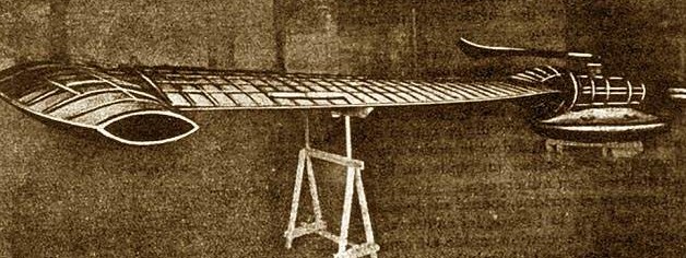
The
completed Gyroptere awaiting tests on Lake Cercey on 31
March 1915.
[ Click to enlarge ]
[ Click to enlarge ]
https://i.ebayimg.com/images/g/6jgAAOSwiIxaJAR5/s-l400.jpg

https://www.pourlascience.fr/sd/physique/le-gyroptere-nait-enfin-2245.php
Le
gyroptère naît enfin
Le rêve aéronautique de deux ingénieurs français des années 1910 devient réalité... mais en taille réduite.
[ Click to enlarge ]

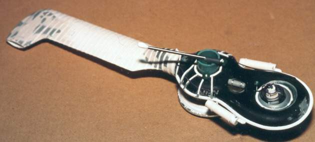
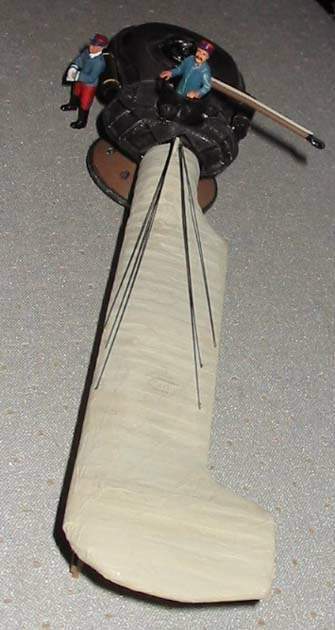
http://modelbox.free.fr/photoscopes/Papin_Phot/index.html
Scratch
1/48 Papin Rouilly Gyroptère.


[ click to enlarge ]

 ''
''


Patents
Abstract
Line-throwing apparatus. -Relates principally to helicopters, but is also applicable for use as rocket and line throwing apparatus, in which the car is carried in axial alinement with the sustaining screw propeller, which is of the Barker'smill type, being rotated by tangential jets of gas, and consists principally in using a propeller with only one blade ; but where more than one blade is used, special apparatus is provided for drawing in the air which is forced out at the tips for rotating the screw. With two blades, the motor unit is at the centre, but with one blade, the unit is placed so as to balance the blade. The boss 2, Fig. 6, enables the machine to rest on the ground or on water, while the blades are still revolving. The engine 4 may be of any type, and when of the rotary radial cylinder form, or turbine type, the fan-wheel 5 is mounted on the engine. The fan is enclosed, and the delivery passage, which is controlled by a valve 6<b>, is connected by a duct 8 to the nozzles. The exhaust gases may be passed into the fan. The fan inlet is on the tcp of the casing, and provision is made for drawing in small quantities of water, and the delivery passage may pass around the boss on the sime side as or opposite to the position of the discharge nozzles. The rudders or steering- planes situated at the blade top are actuated by compressed air. The car 2<a> is mounted on the boss of the propeller, Figs. 20 and 21, on a footstep bearing and with three side rollers 11, a packing- ring 13 reducing air leakages. The footstep is hollow for the control rods 14, 15, which act on the valve of the compressed-air steering-gear. Outside rods 16 coact with a cam edge 2<b> when this is lowered by the hand-lever 19. The rods 16 actuate a valve on the gear which produces an inclination of the screw relative to the car for the purpose of getting a propelling as well as a lifting effect. Rings 20, brushes 21, and a switch are used for controlling the ignition current of the engine. For keeping the car fixed, a rudder vane 23 is opened out and closed as desired when the propeller revolves. A second rudder 25 is raised and feathered so as to bring the car automatically head to wind.
US1133660A
HELICOPTER
[ PDF ]
Procédé pour assurer la sustentation et la propulsion de corps plongés dans un fluide
[ PDF ]
FR440594A
Hélicoptère
[ PDF ]
AT63082B
Schraubenflieger
[ PDF ]