Luigi ROTA
Universal Current Devices
Universal Current Devices
https://wikirota.org/
Pre-electric telluric energy can be collected, focused, and beamed for secure communications, detection, and transmission of power, and levitation.
See also : ROTA, L. : Levitation Apparatus
Luigi
Gino Valerio Rota

Luigi Gino Valerio Rota was born on July 1, 1886 at Lu Monferrato province from Alessandria in Italy. He made studies of physics in Turin at the beginning of the 19th century, and settled in Marseilles before joining England where he was between 1917 and 1921 the first foreigner working in the research laboratories of the British Admiralty. It is at that time that he was invested in work on the microwaves which allowed the discovery and the development of the first radars.
Listening
to telluric currents (1886-1951).
Louis Rota was particularly interested in telluric currents and designed devices allowing him to detect and analyze them. After years of research, he concluded that these were phenomena more fundamental than electro-magnetism and called them "universal currents."
After years of research, he concluded that these were phenomena more fundamental than electro-magnetism and called them "universal currents."
After his death in 1951, his tools and archives were dispersed, his laboratory destroyed, his knowledge lost.
“Universal Currents”?
LGV
Rota is also our grandfather. By discovering what little
we have left of him, we are trying to understand how he
managed to obtain such financial support for his research
for more than 40 years. By publishing all the archives
concerning him, we hope to collect other elements to shed
light on the journey of this extraordinary p
https://www.newspapers.com/newspage/80679613/
The Washington Times from Washington, District of Columbia · Page 7 (February 26, 1922)
Telluric
Current to Open Vast Realm, Says Scientist.
By
F. A. WRAY. International New Service. LONDON, Feb. 25.
IT HAS UNCANNY FORCE
Harnessing of Earth's Elements Now in Bounds of Possibility. An invention that will revolutionize the world! This is the claim of a young, almost unknown, Italian scientist, Professor L. V. Rota, who claims to have discovered the secret of telluric currents. "My invention," states the professor, "can cause battleships, submarines, aeroplanes and guns to crumble to dust at any moment that any government gives the order to move them.
Speed up Travel.
It can be harnessed up for the service of man and can immensely speed up travel, transport and communication, whether by land, water or air. It can cheapen-*very sort of manufacture and enhance every domestic and social immunity. "For instance, a cargo of mails or goods could be sent across the Atlantic through the upper air, without a human being aboard the craft, at a speed of ten to 400 miles an hour. The vessel would rise vertically the prescribed height, travel horizontally in a predetermined direction and drop gently and punctually upon its destination.
"Travel Any Distance."
"Wireless messages, dispatched from no costly or elaborate stations, would travel to any distance free from all danger of dissipation or confusion and with absolute privacy as between sender and receiver. "The nature of all mineral and oil deposits in any part of the world and their depth and volume will be accurately determined without so much as sinking a shaft. "Currents rushing through the air will provide the householder with cheaper, safer and more brilliant lighting than he has ever ventured to desire. "A new power for every Industry will first make coal, steam, oil and electricity more efficient and afterward will dispense with them altogether. "When our company Is formed? within eighteen months ? we will give spectacular demonstrations that all these things?and more?can be accomplished."
Currents Long Suspected.
The existence of these currents, which emanate from the earth (hence their name) have been suspected by other scientists. Lord Kelvin before his death declared their reality. Professor Rota claims to be the first to discover and record them. They may also be described as "molecular force," and they must not be confused, says the professor, with Ampere's thermo-electric currents or with Foucault currents. It is the study of these telluric currents, in their nature, intensity and direction, that is believed to open up such possibilities of tremendous Importance for the future of humanity. Professor Rota has recently given a preliminary demonstration at Marseilles. With a cigar-shaped apparatus, seventeen feet long, thirty Inches In diameter and weighing 200 pounds, he convinced a number of press correspondents that this apparatus could remain suspended motionless In the air for twenty-four hours, carrying a considerable weight, and be propelled or stopped without the use of any mechanical motor.
The
work of Luigi Giovani Valerio Rota ( 1886-1951 )
By
Mike Watson
By
Mike Watson
Introduction
L.G.V. Rota was a Frenchman of Italian origin. He was born 1886 and died in Genesieux near Valence, France in 1951. His early life is relatively unknown. He was involved in early aviation and experiments in wireless communication and also anti-gravitation. He originated in northern Italy and was contemporary with Marconi so that he was almost certainly influenced by his work. Rota wrote little about his discovery: The Universal Current. He produced two short booklets, based on seminars, one in collaboration with a medical Doctor Kresser, and another in which he briefly outlined his work, but with only general details as to how the universal energy he claimed to have discovered was tapped or used. Neither was there any significant theory. However, Rota did discuss his research with one or two confidants, notably a man called Slade who wrote some articles on Rota’s work. Later, after Rota’s death the author visited his laboratory, obtained some of Rota’s laboratory notes and examined some apparatus. Some years later the author met Rota’s son and he showed me apparatus and notes I had not previously seen. Using this data and after many experiments over the years, it has been possible to piece together to some extent a coherent idea of Rota’s discoveries.
Around the time of the end of first world war, Luigi Giovani Valerio Rota discovered a new naturally occurring non-electromagnetic energy which, he claimed, controlled the manifestation of all matter. This energy, which he called the Universal Current, flows some few meters below the earth’s surface. The energy flowing within the earth generates a field in the atmosphere. It was tapped by large buried laminated metallic structures which Rota called blocks. The energy could light lamps, power machines, inhibit electromagnetic propagation such as radio waves and stop or control electromagnetic induction, and also develop antigravity effects and is involved in the life process. Rota maintained that all matter is made of condensed Universal Currents and that any metal could be slowly dissolved releasing the condensed Universal Currents from which it was made. The enormous energy developed during the dissolution of matter could be harnessed. The released energy was not in the form of charged particles but in the form of more Universal Current, which in turn, could be converted into electrical energy. The Universal Current was generally (but not always) harmless and although similar in behavior to electricity it is much more fundamental. Rota understood electricity as a degeneration of the Universal Current. In short, matter is composed of nothing but Universal Current and could be decomposed back into it.
Early research
Rota’s early interests seem to have been in aviation and possibly early wireless transmission, but there is no information surviving from this period. At this time (1910-1915) he had a laboratory in Marseilles and it was there that he devised and experimented on several unusual aircraft which finally resulted in what he called the “Stabilisiteur” (a description is given later in this document) which he defined as a device that floats weightless in the air. He claimed:
“The device works by opposing the magnetic and electric field of the earth rendering the device weightless”.
This claim would at first sight appear impossible, nevertheless the device worked and later a version was given a public demonstration and reported in the press at the time. During one of these experiments he touched the Stabilisiteur and received an enormous electric shock which rendered him unconscious for 50 minutes. Rota said that the voltages and currents used in the machine were very small and he could not understand how a potential of such a large magnitude build up. The search for a solution, ultimately lead him to the discovery of the Universal Current. This unknown energy, he thought, had amplified the small electric current used in the machine.
Around 1910-1918 on the suggestion of one of his teachers Rota seems to have been involved in investigating earth currents. Lord Kelvin had advanced the notion that due to non-uniformities in the earth’s magnetic field earth currents are produced as the earth rotates in its own magnetic field. Rota’s notes of the period show that he thought the telluric currents originated deep within the earth itself and were not external in origin, in short, he had adopted Lord Kelvin’s view. He found that magnetic fields produced by these currents were perturbed by the presence of ships aircraft etc and Rota used this effect to locate the position of ships and aircraft at a distance. He took out patents on the associated apparatus, the text of which is below, and he used a version of it in all his later research. Although he thought that the magnetic disturbances which the apparatus was detecting were caused by telluric currents, around 1923 he started to change his mind. Sometime later he finally decided that the apparatus was detecting a much more fundamental energy of which electromagnetism was a mere byproduct, this energy he called the “Universal Current” because, in his view, it lay at the root of all physical phenomena including the life process.
Although his first laboratory was in Marseilles in the south of France, from the early 1920’s to the end of the 1930’s Rota had a laboratory in northern France near Rouen at Mont-Saint-Aignan. Around the outbreak of the 2nd world war he moved close to Romans near Valence in the south of France and set up a new laboratory there. Both the Rouen and Romans facilities were quite large. He was evidently quite wealthy, his early work being funded by a family friend and it seems that between the wars on at least one occasion, he was under contract to the French government.
My Interest
I became interested in the research of L.G.V. Rota after reading an article on his work in a long defunct popular fringe science journal called the Modern Mystic and Monthly Science Review. The article was entitled "Universal Currents" by a person writing under the pseudonym of Layman. The editor of the Modern Mystic, A.R.Heaver knew Layman. It turned out that Layman was a retired geologist by the name of Slade, who got to know Rota well over the years between the wars, and the three articles in the magazine were an educated layman's account of the bits and pieces of information that Rota had imparted over this period. These articles are included below.
When the author met A.R.Heaver in 1958, the Modern Mystic and Monthly Science review had already been defunct for some ten years. Also both Layman and Rota had died, but Heaver put me in touch with a man who had known Rota since childhood, he also knew most of the people in the area in which Rota had his laboratory. A visit to what remained of Rota’s laboratory was organised and it transpired that some of Rota's equipment was still fairly intact although some of the equipment had been removed and some dumped in an outhouse used by a local farmer as a shed. I managed to finance the digging up of one of the many metal blocks that Rota had used to tap the universal current, and subsequently brought the block to England for examination.
Some 16 years later, out of the blue, I was visited by a Frenchman, Guy Leblond, who knew about L.G.V. Rota and he informed me that Rota had a son. I shortly afterwards met Rota's son, Daniel Rota in St. Malo in northern France. Daniel Rota was only a small boy when Rota died and he knew that his father had made some important discovery, but not being a scientist he understood little about it. However in the intervening 16 years since I had visited Rota’s laboratory he had brought most or all his father's papers and laboratory equipment up to his then house in St. Malo . He allowed me to see and photograph the equipment (some of which are shown below).
Sometime later Guy Leblond unexpectedly visited me with a piece of Rota equipment I had not previously seen. Leblond said this was called the "Transducteur". I had not been shown it previously because Daniel Rota believed it as containing Rota's "secret" regarding the universal current. It seems that the in part Transducteur amplified the Universal Current sufficiently so that they could heard without electronic aid, since Rota invariably used headphones and even galvanometers to detect the Universal Current.
Background
Natural electric currents called telluric currents were well known to 19th century scientists. These electric currents are due to induction from disturbances of the earth’s magnetic field caused by solar flares and storms. Magnetic storms induced quite heavy electric currents in the earth’s surface which, while they lasted, blocked telegraph transmission. The sensitivity of the apparatus of the time to disturbance was due to the use of an earth return in the telegraph circuit. The earth return consisted of large buried metal plates one at each end of the circuit. The telegraph circuits stretched sometimes 100 Km in length and consequently magnetic fluctuations due to solar magnetic storms would induce currents in the overhead wires causing spurious telephone/telegraph signals. Magnetic devices such as electrical transformers relays etc. would saturate. On some occasions the electric currents would reach formidable levels. It is likely that the disturbing currents which existed in telephone wires and the rather strange behaviour of these disturbances interested Rota and led to his research. This is not unknown today.
Excerpt From A Letter from L. Rota ( January 1920 ) :
Sir,
Not alone the press but large number of individual scientists are striving painstakingly and anxiously to explain the origin and source of the mysteriuous signals intercepted at various wireless stations a week ago.
Seven yars have passed since I beganm y reseraches intothe problem of which these phenomena are the outward signs, that is to say into the question of:-
1. the source of terrestrial magnetism
2. The real nature and constitution of the true center or core of the earth.
3. The derivation of seismic phenomena
4. The propagation of electric waves and everything that this wide field of research covers today.
It was while engaged in this study that I came upon what I believe to be a discovery of the most scientific import that may yet favorably revolutionize the natural sciences especially insofar as they concern electricity or electric waves, and one which, in any future war that may unhappily arise is destined to afford to the nation wise enough to exploit it to the full an insuperable means, either of offense or defense...
Unidentified Letter :
...In the convenient circumstances mentioned, Prof. Rota diligently continued his researches concerning Telluric Force more especially in relation to seismological and meteorological conditions. In the course of these researches he found that not only does Telluric Force undoubtedly exist in and emanate from the earth, but he satisfied himself that Telluric currents have a range of not less than 300,000 miles.
Telluric currents must not be confounded with Ampere thermo-electric currents or with Foucalt currents.
Teluric currents vary in their specific nature, intensity, direction, and limits of influence.
The idea of employing these Telluric currents as means of power naturally followed and Prof. Rota therefore directed his attention to the invention of instruments for detecting, collecting, concentrating, controlling and so applying these currents that the employment of such instruments would enable the successful commercial exploitatio of Telluric Force...
Excerpt from : Daily Herald ( 25 July 1921 )
Latest Marvels Of Science ... Power To make A New World ... Telluric Currents ... Startling Claims Of A Young Scientist
A company is about to be floated to work the invention of a very great, but little known scientists, whose discovery, if it fulfills his claims, will literally revolutionize the world.
This fact was disclosed to me yesterday [writes a Daily herald correspondent] by two financiers in their office in the City of London.
This invention, I was told, is one that can cause battleships, suibmarines,aeroplanes and guns to crumble to dust the moment any Government gives orders to move them.
UNMANNED CRAFT
That was only the beginning of this marvel. The mysterious force about to be harnessed for the service of man would immediately speed up travel, transport, and communication, whether by land, water or air, and cheapen every sort of manufacture, and enhance every domestic and social amenity.
For instance, a cargo of mails or goods could be sent across the Atlantic through the upper air, without a human aboard the craft, at a speed of 10 to 400 miles an hour. The vessel would rise vertically to a prescribed height, travel horizontaly in a predetermined direction, and drop gently and punctually upon its destination.
CHEAP WIRELESS
Wireless messages, dispatched from no costly or elaborate stations, would travel to any distance, free from all dange of dissipation or confusion, and with absolute privacy as between sender and receiver.
The nature of all mineral and oil deposits in any part of the worldand their depth and volume will be accurately determined without so much as sinking a shaft.
Current rushing through the air will provide the householder tiwh cheaper, safer, and more brilliant lighting that he has ever ventured to desire.
OLD POWER MADE OBSOLETE
A new power for every industry will first make coal, steam, oil and electricity more efficient, and eafterwards dispense with them altogether.
Within 18 months, I was told -- and in accents of conviction -- the company will be operating, and a spectacular demonstration will convince the world that all these wonders, and more, can be accomplished.
The secret is "telluric currents", and the discoverer is a young Italian scientist, Professor L.V. Rota.
The existence of these currents, which emanate from the earth (hence the name) has been suspected by other scientists...
Excerpt From Another Unidentified Newspaper Article :
..."My studies have led to the discovery of three classes of telluric, or earth currents, never previously defined. These currents have no analogy with Ampere's thermo-electric currents. The late Lord Kelvin proclaimed, shortly before his death, the existence of an uknown telluric current, but without further defining it. It is evident also from newton's lete to Bentley in 1691 that the discoverer of the law of gravitation had some suspicion of a law of universal attraction. These telluric currents vary in their specific nature, their intensity, direction, and limits of influence. Their radius of action is immense, their action very powerful, and they cause the natural phenomena which scientists have endeavored in vain to explain.
Telluric Currents
These telluric currents have brought about an atmospheric condition which renders impossible the formation and condensation of clouds, hence we have not had our usual rainfall, because they also control the electric state of the atmosphere, and they absolutely master the formation of all electric storms. Given full knowledge of the laws which govern telluric...
https://wikirota.org/nature-et-detection-des-courants-universels/
Nature and Detection of Universal Currents
1. Presentation
2. Buried probes or blocks
3. An important discovery
4. The differences between the Universal Current and electric current
5. Synchronization
6. Detection Problems These Days
7. Block construction
8. Portable Blocks
9. Field detection
9.1 Working method
9.2 Portable devices
10. The hypotheses of L.G.V. Rota
11. Dr. Watson's investigation (2/4)
1. Presentation
Extract from patent GB129069 (May 28, 1918)
Rota wrote in a lab note: "At first I thought that telluric currents were magnetic in nature and accordingly I undertook experiments in the concentration of long wavelength electromagnetic waves using the earth as a collector."
Today we would call them low or very low electromagnetic waves (LF,TBF), but we will see that this leads us to something much more important.
Before moving further into the heart of Rota's discovery, the universal currents require some explanation. Rota used a stopwatch and headphones to detect his currents. It is therefore a purely physical process. Rota began by studying telluric electric currents created by induction resulting from variations in the Earth's magnetic field. In his notes, Rota mentions Lord Kelvin's theory proposing that these currents come from the rotation of the earth in its non-uniform north/south magnetic field (the magnetic north pole not coinciding with the axis of rotation of the earth) . Rota took up Lord Kelvin's idea that telluric currents or electrical currents underground are entirely of terrestrial origin and without external contribution. As mentioned above, telluric currents disrupted the first telegraph installations which had only a single wire mounted on poles and a return to earth via buried metal plates. Rota undertook the study of variations in telluric currents noted by telegraph operators in search of systematic occurrences. He also noted that moving boats cause low-frequency potential variations on a metal cylinder submerged in water compared to another cylinder left above water. He extended this idea to aircraft detection and exploited this discovery by developing a special detection device which he patented (GB128624, GB129059, FR536324).
At first, Rota thought that planes and boats disrupted the magnetic field of telluric currents that he believed continually circulated in the earth, and that his patented device detected these disturbances. However, towards the end of the First World War, he carried out ground radio transmission experiments. He discovered that in certain places, the signal variations between insulated metal rods planted in the ground and insulated wires of another metal buried at a certain distance depended on the nature of the metals of the rod/wire pair. He also noted that the use of different pairs of metals simultaneously showed different signal variations. From these observations, he concluded that the electric currents he had transmitted through the earth had “an interior content” depending on the metal used. He also discovered that certain metals transmitted signals into the ground in certain directions better than others, and that when the receiver's buried antenna was made of the same metal as the transmitter's, reception was better.
This suggested to him that the radio signal was transmitted into the ground by a directional "emanation" from the metal, and that this emanation was strongly influenced by the direction of the Earth's magnetic field. At that time, powerful spark transmitters were still used for radio communications. We can assume that he extended this concept to natural telluric currents, considering them as "metallic emanations" coming from the depths of the earth and carrying electromagnetic energy. Something comparable to ionization which we will talk about later.
Electric potential, as Rota understood it, is a property of its carrier agent. It should therefore not be considered as a single thing in itself, but as a property of a mixture of several components. The different metals, each being more sensitive to a specific component, separate this mixture. Rota understood that these fundamental components revealed by the different metals were more important than the simple overall electrical potential, because the emanations of the metal could, much like the ionic jets, carry additional information. He noted that the emanations of metals comprised a certain number of components which he called "universal currents" since each component existed universally in nature and any mixture of these currents contains an electric potential and always circulates as an ionic current . However, these metal emanations, which resemble the ions well known to chemists, appear to possess other properties.
Rota employed deeply buried metal probes to detect soil potentials. He called these probes blocks. They were made of laminated strips of several metals (iron, tin, lead, zinc, cadmium, nickel, etc.). As the blocks were isolated from the surrounding ground, it is clear that he was only interested in potential variations resulting from capacitance/inductance coupling in the probes or blocks rather than direct conduction. (It is possible that the ions produced from the metals in the block could actually penetrate an insulating varnish, but the blocks I dug up showed no signs of the corrosion despite being buried for over 20 years).
However, the initial blocks were probably not isolated from the ground. An important network of very large cables connected the blocks to the laboratory. Two blocks separated by approximately 200 meters constituted an induction loop for the universal current(s) of the earth.
Rota manufactured the buried elements with plates of different metals. These assemblies formed a laminated metal structure that Rota simply called a “block.” A block, once buried, would capture all common location types. Other locations turned out to have different groups of currents which required the use of blocks made of other metals. (See Fig. 1, 2, 3)
The blocks (fig 1) were buried in some cases at a considerable depth. Rota could detect telluric currents, using a galvanometer or conventional headphones. If then made a crucial discovery: the strength of the current detected by an instrument depended on the type of metal used in the block, thus suggesting a relationship between the nature of the metal and the telluric current. By studying these telluric energies, he found that of two blocks buried nearby but made of different metals, one gave a good response while the other gave little or no signal. Additionally, on other occasions two adjacent blocks might be active and a third not at all. The block became a means of capturing specific current groups of a place. Capturing different currents required blocks made of different metals.
The yield of these blocks then became significantly greater as the quantities and types of metals used were adjusted. Interestingly, the mass of the metal was large. The arrangement of the different metal plates constituting a block had to correspond to the detected telluric energy to obtain a maximum signal. Furthermore, the power of the blocks improved over the years without any external action. This “acclimatization” process took approximately four years.
Rota noticed that with a pair of headphones he could hear the telluric currents which gave a characteristic note when connected to the blocks. Each block returned a different note, or more correctly a characteristic tone; the rating changed periodically over a period of time ranging from seconds to months. The periodicity meant that he could get the same tone from a given block after a known time. He then realized that there were many different kinds of telluric current, each giving its own sound in the headphones connected to a given block, each fluctuating in a characteristic periodic fashion. He later claimed to have found 361 different types of telluric current. All currents have a fixed and generally different direction in the earth. Their intensity and what Rota called their density change, but their direction is always fixed. The rise and fall of these parameters occurred at fixed times, which allowed Rota to predict in advance when a given current was going to be active.
3. An important discovery
As mentioned previously, there is a link between a given telluric current and a specific metal. By experimenting with blocks of simple metals such as copper, zinc or iron, he found that a given metal was sensitive to more than one telluric current. However, the number of telluric currents discernible by common metals was relatively small. Thus copper is sensitive to four specific currents and zinc to six. Rota noted that the blocks gradually amplified the currents. This led him to the following important discovery, taken from one of his documents:
"I was able to discover and prove how, by placing a metal of whatever nature it may be in the direct and appropriate presence of its own original intrinsic current, one manages to awaken the latent energy of this metal and consequently to be able to have access to immense free energy for all kinds of industries and their applications."
If a buried metal emanates a certain category of penetrating ions, then this statement is a normal consequence. The metal as a source would run out over time.
Rota concluded that telluric currents must be much more complex than electricity. According to him, electricity would be the result of the action of two telluric currents and three magnetic currents, i.e. an interaction of five components. Even universal attraction would have a base current. His original views will be discussed below in more detail.
His ideas moved away from the concept of a metallic emanation and he obviously thought that electrons were not all the same. Furthermore, at some point Rota decided that telluric currents were not confined to the earth, but came from the cosmos and seemed to play an important role in nature by existing everywhere on earth including in living beings. For this reason he named the telluric currents that he had detected “universal currents”.
4. The differences between the Universal Current and electric current
One of Rota's lab notes says this regarding electricity:
"What we call in physics Static Electricity is an imponderable which results from the action of two natural energies; the latter are part of a set of cosmic energies whose existence and effects I discovered. These two energies have their own specific properties but they are capable of forming only one energy when certain conditions are met; we see an analogy between natural electricity and that produced empirically in the usual way. Three natural currents, different from the first two, give rise to an energy called magnetism. The result of these five energies working together is what we call electromagnetism. Thanks to the intrinsic properties of each of them, these currents can, depending on the elements they encounter either in nature or dispersed by the hand of man, produce effects that are currently misunderstood."
This raises the question of whether electromagnetism always consists of the same energies. For example, is the electricity produced by a zinc and copper battery the same as that produced by an iron and zinc battery? This would have nothing to do with volts and amperes, but would be linked to the “internal structure” of the electric current. If electricity is of external and cosmic origin, then the "internal structure" is always the same. This view requires that the act of generating electricity is a process involving the attraction of an external energy: a specific group of universal currents. Rota's original telluric currents had a behavior very similar to that of a current of metal ions. Whatever the origin of electricity, the components of universal currents apparently do not act or react with each other. Since the exchange mechanism occurs only when the currents are active, the currents can be considered static and inert. We will see later that these currents are active in biological matter and life depends on such actions and reactions. Stopping this activity causes the death of the organism.
In any case it is important to note that physical instruments would be blind to the universal currents constituting electric current, the instruments detecting only volts and amperes. Therefore two different groups of universal currents having the same voltage and tension would be seen identically by voltmeters and ammeters even if the constituents were different. Universal currents in an electric current could be chaotic, which is probably why Rota indicated that electric current is a degradation of its universal current components. When the metals involved in producing an electric current are "awakened" the detected electric current is the result of the action and reaction of the constituent currents in a coordinated manner. This produces a characteristic tone that can be seen as a waveform on an oscilloscope or heard in a pair of headphones because of the large fluctuations in potential as the various components synchronously add and subtract. “Awakening” is an attunement effect that Rota called Synchronization. The high potentials produced in this way caused the shock Rota received during his early experiments. An analogue to this process is an orchestra. If members play randomly, there is just background noise, but if they play together in a coordinated manner, a tune is heard and also much louder pulses of noise.
To summarize, the difference between universal current and electric current is that the latter would be a group of five static interior components (i.e. without action/reaction) while universal currents act and react in a specific way. cyclic. A metal can be activated, which means that the currents that compose it act and react with each other. The awakening of a metal is a process called synchronization. Later we will see that biological matter contains universal currents which act and react between them and that these exchanges cease upon the death of the organism. Electricity no longer acts and reacts and so by this standard it is dead. The universal current which reveals these exchanges can be considered to be “living electricity”.
5. Synchronization
Let's return to the blocks used by Rota. When a multi-metallic block is first buried in a metal-appropriate location, the different metals are dormant. Over time, metals become active and produce coherent pulses caused by the reciprocal actions of the metal's current groups and giving that metal a characteristic tone. As mentioned above, in order to hear this activity through headphones, the metals must be activated, their latent energy must be awakened. The tone of a block results from the combined action of the currents of all metals in the block, like an orchestra playing a tune. For example, zinc with six currents gives a tone resulting from the sum of the six currents that constitute it. (This assumes that the zinc metal is awakened by treatment with one or more of its intrinsic currents, otherwise the metal is inert).
If zinc and copper were connected together, the result would be a random mixture of ten different currents, 4 for copper plus 6 for zinc. However, once combined in a buried block, over a period of time, this mixture evolves into a unique sound specific to the block which depends on the metals constituting it. This is the process of harmonization that Rota called synchronization. Accompanying the synchronization, Rota found a large increase in energy produced by the block as if all pulses were occurring in an orderly manner. The pulses produce a characteristic tonal signature. Synchronization takes approximately four years to reach its optimal development. This time frame does not depend on mass or volume: processing 1 kilogram takes as much time as processing 100 kilograms.
Synchronization then occurs in the laboratory equipment used with the currents. All wires, galvanometers, voltmeters, ammeters and telephones become synchronized. In the absence of such synchronization, “discord” strictly prevents the flow of block energy. As mentioned above, ordinary laboratory instruments such as voltmeters and ammeters cannot distinguish electric current from a universal current group. A normal "non-synchronized" ammeter may measure a few milliamps coming from a block, but a synchronized ammeter connected to the same block will show several amps.
It is perhaps useful at this point to point out another much more curious fact. Rota maintained that the force that holds matter together at the atomic level was a force he called "universal cohesion", and that universal attraction, which is proportional to mass, came from this same force. This force was one or a special group of universal currents. He believed that an element consisted of some sort of knot of universal currents (e.g. four currents in the case of copper) linked together by the current binding force of universal cohesion or "gravitation". Rota was well aware that the forces of gravitation were, on the atomic scale, extremely weak, which implies the existence of two forms of universal attraction. The second (bipolar?) is extremely strong (it is the cohesive force in matter) while the first, monopolar, is a microscopic residue significant only in the case of large masses such as planets. He experimented with this second form with his anti-gravity machines.
Blocks
 Connectors
 Lamp Blocks
Connectors Lamp Blocks 6. Detection Problems These Days
As will be seen in the patents cited below, any moving paramagnetic object produces a disturbance that can be detected by an ordinary electrometer. It appears today under the rubric of UBF ([[wikipedia:Ultra Low Frequency|Ultra Low Frequency]] or [[wikipediaEn:Ultra low frequency|ULF: Ultra Low Frequency]]). These disturbances would be produced, for example, by cars and planes. Rota thought that these disturbances came from an interaction between the car or the plane with telluric currents, that is to say the currents which circulate in the earth. He later came to the conclusion that these currents were of cosmic or external origin: one more reason to rename telluric currents "universal currents".
Isolated buried probes will sense a potential difference if the disturbance in the universal current moves such that the probes are influenced unevenly or if they are made of different metals. Initially, the metal pairs produce only a very small change in potential, but gradually the potentials increase as metals in a near-inert state gradually become activated. It seems that Rota spent many years to ensure this effect.
Detecting universal currents unequivocally requires that the probe metal be activated as mentioned above. The metal must also correspond to the characteristic current of the place. If it does not match, the metal will never become active. It is also essential that no chemical action takes place between the probe metal and the earth, so it must be properly isolated and protected.
7. Block construction
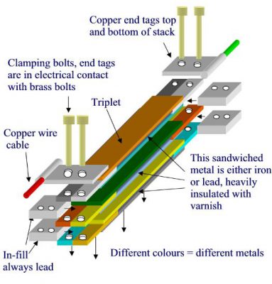
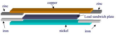
Fig. 2 composition of a "triplet"
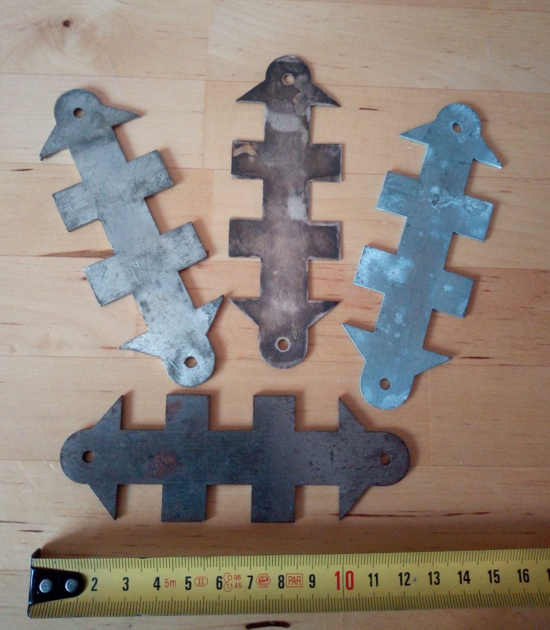
Fig. 3 block of 3 triples
Buried and insulated blocks will sense a potential difference if the disturbance in the universal current moves such that the probes are influenced unevenly or if they are made of different metals. Initially, the metal pairs produce only a very small change in potential, but gradually the potentials increase as metals in a near-inert state gradually become activated. It seems that Rota spent many years to ensure this effect.
Detecting universal currents unequivocally requires that the probe metal be activated as mentioned above. The metal must also correspond to the characteristic current of the place. If it does not match, the metal will never become active. It is also essential that no chemical action takes place between the probe metal and the earth, so it must be properly isolated and protected.
Note that the triplets (Fig. 2) have different combinations of metals. The central sandwich is always lead or iron heavily insulated with varnish. The end tags, in this case zinc and iron, are riveted to the copper and nickel strip respectively.
Example of a block containing 3 triplets (Fig. 3). A block can contain up to 50 triples squeezed together. The total length of a block is approximately 1.5 meters and contains metal strips with a thickness of 1 to 5 mm.
The width of a block is approximately 60 mm.
8. Portable Blocks
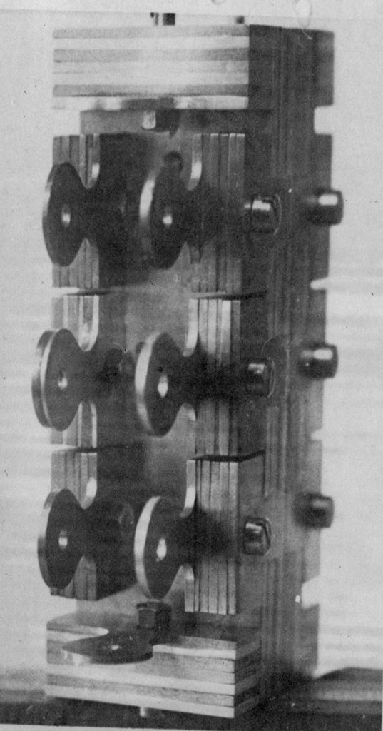
Fig. 4 Small blocks showing layered construction and a thick cable emerging from one of the metal layers
The buried blocks were the source of energy. The energy from the buried blocks could be used to charge small blocks above ground, which were in the laboratory, these small blocks were charged by connection to the buried blocks. These little blocks retained their energy for a few months before needing to be recharged.
The small blocks could be used as energy sources for specially constructed gas discharge lamps. The electrodes of these lamps were made of different metals all made active which were connected to the small power supplies. The lamps were filled with low-pressure inert gas mixtures and glowed with a cool white light. Although the glow resembled common electrical ionization, it was caused by a different mechanism, namely the excitation of the intrinsic currents of the metal and inert gases themselves.
There were other blocks used for medical purposes and also as groundwater research. Detection was done by listening to the currents with a pair of headphones. I should point out that none of this involved dowsing methods, but was a physical process involving actual listening.
9. Field detection
9.1 Working method
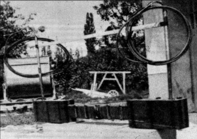
Field analysis
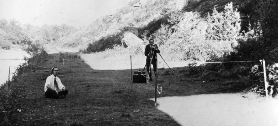
Fig 5: Field analysis
Fig 7: Composition of a probe.
Rota did not do all of his research in his laboratory. He also carried out field operations:
geological research (groundwater, mining research)
military: detection of military works, ammunition depots, etc.,
Figure 5 shows Rota (standing) and his assistant (listening with headphones) testing universal current flows. Note the four sticks in the ground, and a probe rod just to the right of the stick in the center of the foreground.
The black box at Rota's feet and the device on the tripod can be seen in more detail in the following photographs.
Note the probes in the ground arranged in a square N,E,S,W. Each probe was a rod of varnished iron soldered with tin to a copper plate. Also soldered to this plate was a copper rod whose end had a terminal tag soldered to it, using pure tin.
A view of Rota on the right and the assistant on the left.
Rota listens to the currents with headphones and a stopwatch.
In the photo of Rota and his assistant, also note the rods as objects connected to the selector box, these are multi-metal rods. The different metals are connected in series.
The wires go to the ground probes shown in Figure 6. The black box below the switch contains an amplifier block that had previously been charged from a grounded block in its installation.
9.2 Portable devices
10. The hypotheses of L.G.V. Rota
All matter is formed by universal currents.
Each universal current has its own specific properties; Rota had detected 361 different currents by the time of his death in 1951.
Each chemical element is made up of a different group of universal currents, copper, for example, is made up of four of these universal currents.
If an element is exposed to one of its constituent currents, the element disintegrates, not explosively but gradually or more quickly depending on the strength of the universal current.
The constituent currents are held together by a "cohesive force" which is related to gravitation but which, unlike gravity, is polar.
The enormous polar force of cohesion is released when an element is dissolved by a constituent current and can attract or repel ordinary gravitation.
The enormous polar force of cohesion is released when an element is dissolved by a constituent current and can attract or repel ordinary gravitation.
Electromagnetism is made up of five universal currents held together by the cohesive force, three for magnetism and two for electrostatic forces.
Electromagnetic polarity comes from the polarity of the cohesive force.
Electromagnetism can be divided into its universal current components releasing the cohesive force.
The properties of the universal current are strongly involved in the process of life. The process of life divides matter into its common universal components.
Common physical instruments generally cannot detect universal currents directly, only components bound by cohesive force, e.g. magnetism, electricity and momentum are detected.
https://wikirota.org/experimentation/
Summary
1. Another type of telluric current?
2. Louis Rota’s approach
3. Background noise in metals
4. Neon detector
5. Ground radio
1. Another type of telluric current?
(a) Electric current induced by a rotating coil
(b) Rota detector
Extract from French and English patents (GB129059, FR536324) “Improvements made to the means for signaling the presence of explosive mines...”:
"There are certain telluric currents which produce magnetic whirlwinds in the earth. The presence of the intensity of these currents is revealed when a shock occurs between them and a magnetic or para-magnetic body, whatever the latter. Thanks to this fact, it is possible to discover the presence of a mine, a submarine, a ship or other magnetic or paramagnetic body..."
A good starting point is the ordinary telluric current known to physics. Even today many of their characteristics are poorly understood. Telluric currents are thought to be caused by the movement of large quantities of salt water that occurs in ocean currents moving through the Earth's geomagnetic field. Another source would be solar storms which cause fluctuations in the earth's magnetic field and which in turn induce the electric currents which circulate on the earth's surface. Lord Kelvin, 90 years ago, suggested that the rotation of the earth in its non-uniform magnetic field was a possible source of telluric currents. According to his notes, Rota initially thought that telluric currents came from within the earth. The magnetic fields that these telluric currents combine with the north-south magnetic field producing a complex field.
There is another possibility: is the earth's magnetic field fixed in space or does it rotate with the earth? It is not possible to tell this by simply planting two metal rods some distance apart and measuring their potential difference with a voltmeter, because the same voltage would be induced in the voltmeter leads and the device would not measure any voltage. This is equivalent to considering the earth as a homo-polar generator with the earth rotating in its own magnetic field. Considering the irregularity of the Earth's magnetic field, a composite field of telluric currents linked in a complex way to the solar magnetic field would circulate. We are then faced with a conundrum: why did Rota use an axially rotating solenoid instead of a simple pivoting coil which is in fact an effective magnetometer?
Conventionally, the rotation of a solenoid will only produce an output current if the magnetic flux passed through changes (fig. a). Rotating axially would produce no current (fig. b). Rota was well versed in the laws of electromagnetic induction, so it is assumed that he discovered that the solenoid worked by accident, not through an application of known electromagnetic principles.
2. Louis Rota’s approach
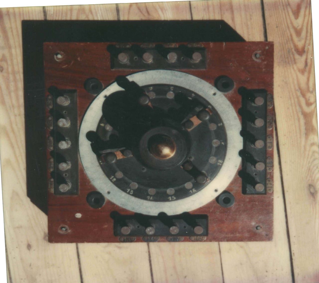
Fig. 10 One of Rota's first devices, This octagonal object is made up of two concentric wooden frames covered with sheet iron.
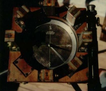
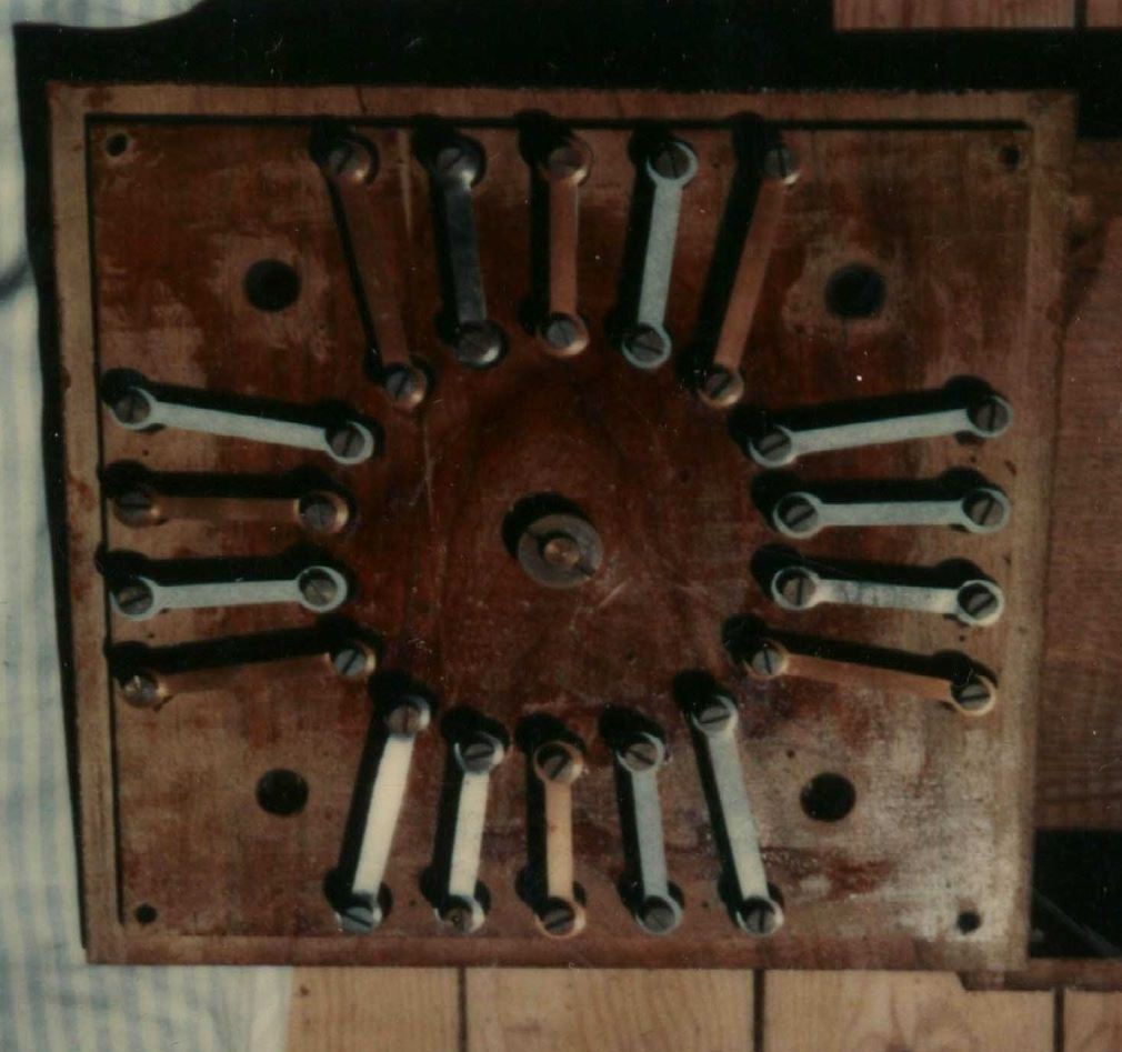
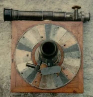
Fig 11 Rota's compass. The top right has a regular magnet needle pivoted in the center. Note the N,E,S,W markings on the plate as well as the 8 small vertical multi-metallic blocks (one missing).
Bottom view of the compass. Plates of different metals such as lead, copper, x, x, zinc, etc. can be seen arranged in sets of five. Also note the telescope.
Rota also said: "Having devoted many years to the study of cosmic currents, I was led, little by little, to verify that these currents have nothing in common with the currents of the earth's magnetic field but have an existence of their own."
The universal current operates in living organisms and this is another factor that takes the universal current out of the ordinary: when life ceases the currents in a corpse have no reaction on the test apparatus constructed of synchronized metals. In this sense, synchronization is the process that brings metal to life, because a synchronized metal acts on the test device in the same way as the response of a living organism.
Rota stated that electricity is made up of five currents. The electrical component consists of two currents and the magnetic component of three. The electric current does not react with the test device, so it is dead: the electric current is a degradation of universal currents. Rota also said that they are of cosmic origin, but one wonders if he is talking about the ultimate origin in the sense that all metals are composed of universal currents of cosmic origin or if he is saying that the act of making electric current attracts these five cosmic forces from space.
If the universal component currents come from the metals as in a simple two-metal and electrolyte battery, then the electric current would be different depending on the metals that produced it. Physical instruments only detect pressure (volts) and current (amps) or the amount of electrical charge (coulombs) and are blind to any hidden contents or variables.
In conventional physics, the electromagnetic field arises from moving and static electrical charges. Because Rota's experiments were geophysical and concerned magnetic anomalies, it is worth giving an idea of the current orthodox view of the Earth's magnetic field.
The Earth's magnetic field is the sum of several contributions, including the main field (core), crustal field (anomaly), and external source fields (magnetosphere). The core contribution dominates the field from the Earth's surface out to about four Earth radii.
Beyond four Earth radii, the Earth's magnetic field is increasingly affected by the interaction of the solar wind with the Earth's magnetosphere. Distortions can be described by several external source fields caused by magnetospheric current systems. Three main current systems can be identified in the undisturbed outer magnetosphere:
a current system on the magnetospheric boundary (magnetopause).
a current system in the neutral sheet of the geomagnetic tail (the surface that separates two lobes of the tail).
a current system around the Earth (annular current) circulating in the equatorial surface (minimum B).
During geomagnetic storms and substorms, substantial changes occur in these systems, in addition to the appearance of field-aligned currents outgoing and entering the ionosphere.
It is reasonably clear that at least some of the disturbances mentioned by Rota are observed today in geophysical observations, particularly very low frequency (ELF) signals, but the bulk of his findings regarding the universal current do not apply. does not fit well into current geophysical observations. In my opinion, the origin of the universal current is not found in the magnetic field B which affects a compass but in another form of magnetism. One of these possibilities is the magnetic vector potential which is undetectable by usual electromagnetic methods. Until recently, the magnetic vector potential was considered a mathematical fiction, useful for calculation but having no physical reality. The Aharonov-Bohm experiment showed that the magnetic vector potential is real. However, a magnetic vector potential requires an electric current or rotating electric charges as a source. The electric currents that travel through the earth are telluric currents induced by solar activity or currents internal to the earth's crust. Another possibility depends on whether the ordinary terrestrial magnetic field is fixed in space or rotates with the earth; if it is fixed, the earth rotates in its own magnetic field inducing electric potentials (Faraday homopolar generator effect) and therefore electric currents. in the earth's crust. We could not measure this potential because the measuring instruments also have identical potentials induced in them because they are fixed to the earth. Such currents would take a wide variety of paths due to different ground resistance and also different magnetic intensity at various locations, etc., which would fluctuate daily as the earth rotates in its fixed field. Although we could not detect the potentials that cause the potentials, we could detect the magnetic effects of the currents caused by these potentials. This fits well with Rota's hypothesis as stated in his patents.
“There are certain telluric currents which produce magnetic whirlwinds in the earth. The intensity of these currents is revealed when they encounter a paramagnetic object”.
For this reason, it seems likely to me that this was the path Rota took in his first experiments 90 years ago.
An ordinary electric current as produced by a common dynamo will not synchronize a metal so, if we adopt this hypothesis, there must be something special about the Earth's magnetic field and the electric currents it induces. To match Rota's findings, there is an additional variable present in earth currents that can "awaken the latent energy of the metal" which is what synchronization is.
Another interesting idea is that the universal current is a neutral magnetic charge current. Magnetic charges (magnetic monopoles) have been searched for by particle physicists but have never been found. The great physicist Paul Dirac discovered that its existence was sufficient to cause the quantification of electric charge. Particle physicists believe that if they existed, they would only appear in very high-energy experiments and would not be free in nature. If they exist freely in nature, why are they not easily detectable. One reason for this could be that magnetic charges exist as magnetically neutral pairs or groups of equal N and S pole charges forming a neutral magnetic current.
There are indications from the experiment that something similar was detected first by Ehrenhaft and recently by Mikhailov when very fine dust particles are illuminated by a bright light source. Light is necessary to give rise to the unipolar magnetic charges that form in pairs. Mikhailov seems to think that this only happens with iron particles while Ehrenhaft also found the same effect with copper particles. What is interesting is that the light seems to have the effect of revealing some kind of magnetic charge that is not usually detectable. Matter is externally electromagnetic (nuclear components only appear in more extreme conditions) and the magnetism around magnets and coils of wire carrying an electric current is caused by a rotating electric charge or a moving electric charge.
In this respect, the universal current is analogous to a piece of soft iron in which the magnetic domains are randomly oriented and therefore has no external magnetic moment, but if placed in a magnetic field domain alignment externally, the iron temporarily transforms into a magnet. Figures 10 and 11 certainly suggest that something similar is happening with the universal current, one might expect that, like iron, the universal current is magnetizable, although it has no magnetic moment of its own . The Earth's N-S magnetic field would align the components of the universal current but it would not be possible to separate the effects due to the Earth's magnetic field from the additional effects caused by the universal current. It was only when Rota discovered that the universal current has different components that it was possible to separate these components from the effects of the Earth's magnetic field.
3. Background noise in metals
Schema of the experiment
LGV Rota claimed that atmospheric disturbances or background noise from radio sets are due to the metals of the set and the antennas responding “to universal currents”.
With a tape recorder I compared the effects of atmospheric electromagnetic signals on several metals. Are these signals just a random phenomenon or proof of another property of the metal?
Some floors produce nothing except a 50 Hz hum.
To work without a cassette recorder, a metal probe or a metal block connected in series with the probe must be activated. I don't know how to activate this. Rota had a method that he kept secret. His portable pad with inscribed Roman numerals served as an amplifier.
Current indicators in Louis Rota's notebook such as +9 IV 46 V+ etc. indicate reactions on the drinking block. The IV is the plug number on the block box. 9 is probably the number of reactions heard in the headset.
The currents pulse rhythmically.
Did Louis Rota use electronic amplifiers? Probably not.
The oscilloscope images above are taken from the cassette recordings. There is a 50 Hz noise floor which requires filtering. This is undoubtedly why Rota moved from Rouen to Génissieux
4. Neon detector
R1 is 1 Megohm
R2 is 100 Kohm
R3 is 100 ohms
CX1 is 0.02 microfarad
Here are some simple experiments that demonstrate the basic elements of Rota's patents using a simple electronic device. I call this the neon detector.
This circuit reveals the fields surrounding heavy moving objects. It was discovered more than 65 years ago by T.B Franklin and J.C. Maby. They discovered that they could detect planes and trains from several kilometers away. At the start of World War II it was studied by the British government as an aircraft detector, but when radar was developed it was abandoned.
It works like a Geiger counter.
Adjust R2 to maximum ohms and gradually turn R1 from zero until the neon starts to light up as heard in phones in the form of a clicking sound. Reduce R2 until the click becomes erratic and adjust R1 until the click rate is approximately 1 per second. Reduce R2 to just above where the clicks start to appear in groups. If no click occurs, reverse the polarity of the neon.
Some 85A2s are better than others for this detector.
Go to an uninhabited area as far from human habitation as possible. Mount the detector on a tripod and drive a car with the engine off down a gentle slope toward the detector. You'll notice bursts of clicks at fixed distances from the car and places where the click rate is reduced in between. The moving car appears as if it is surrounded by areas at fixed distances from it. This can be easily computerized.
It appears that there is an ambient field that is disrupted by heavy moving objects and the effect is as if the object is surrounded by spherical ripples of several meters in wavelength. Before World War II, J.C. Maby discovered that planes could be detected at great distances and trains at 12 km. Remember, there was much less car traffic and airplanes in those days, so it was easier to see these effects clearly than today.
It appears that there is an ambient field disturbed by heavy objects, including paramagnetic objects such as cars. This is essentially what Rota said it detects and what neon detects.
Many unknown effects are detected with this device. For example, a vertical steel rod has four fan-shaped beams radiating in the N,E,S,W direction.
5. Ground radio
Additionally, various people have experimented with grounded radio antennas.
In theory these should not work at received/transmitted frequencies but they do except that the reception/transmission shows strange variability. There are a number of websites devoted to ground radio.
http://www.borderlands.com/newstuff/research/FelixRadio/FelixRadio.htm
http://www.borderlands.com/newstuff/research/ground-myst.htm
Rota appeared to begin by transmitting a radio signal through the ground using an induction coil and presumably a spark gap system as used in Marconi's early radios. I suppose he must have noticed that signals sent through the ground by grounded metal probes radiated differently in different directions. From his notes it appears that he worked extensively on the ship detector whose patent is pictured above.
It is assumed that the directional effects of water transmission persisted. Additionally, the directions were found to be metal dependent.
By moving the detector around the transmitter at a certain distance, you will find that the signals transmit better in some directions than in others.
By 1919, Rogers and Jones held patents on ground-based radio communications. Here are some of the diagrams of these patents. They are very close to the experiments that Rota was doing. Rota obviously found that putting a block of metal in the transmission circuit slowly improved the transmission in a given direction and this was what he called synchronization. It would seem likely that the very high voltages used in the transmission of the sparks contributed to the enhancement of metal radiation due to something close to ionic diffusion of the metal.
A.R Heaver who published the "Layman" articles on Rota cited above in full stated that Slade (Layman) had mentioned that Rota had stated that the metal ore deposits "grew" into the ground from current currents universal. Mines, where a metallic ore was mined, usually had the universal current associated with the metal of the nearby ore. This idea suggests a kind of ionic current which, over geological time, deposits a metal.
Another thing, which points in the direction of some sort of ionic flow, is seen in the medical work that Rota did with Dr. Kresser. The detection of universal currents in a human being is done by action on a metal test tube, all vital functions are of an ionic nature, so here is a parallel between the ionic state and the universal current.
6. Listen to the “Rota effect”
I performed the following experiment in 1960.
When I began listening to Rota's currents on the dug-up block at his laboratory site in 1959, I heard nothing through headphones or any other means. Someone pointed out that when Rota made a medical diagnosis (see Medical Applications), he stroked metal rods held in the patient's hand.
I tried a similar thing using metal discs as shown below. I heard several variations in click intensity when one of the phone contacts was touched by metal, but quickly discovered that this was due to 50 Hz sampling on the mains of the house wiring . Doing the same thing in a remote area showed variation, especially if a short antenna was used. It was found that the click was due to the high inductance of the high impedance earphones storing a minute input current and releasing the stored energy as an inductive click as soon as the contact was broken. The variations found were due to ultra-low frequency signals on the order of 0.01 Hz or less. Note that Rota used a stopwatch, as seen in the photo on the main page of this site, so the variations he heard must have had a long cycle time.
This experiment must be carried out with two sets of insulated metal plates buried deeply and separated by a few meters. Again, it needs a site away from 50/60Hz mains wiring to be effective. The great advantage of this method is that it is completely passive, with no electronics to give parasitic leakage currents.
It is worth repeating what is mentioned elsewhere on this site[1] :
Maxwell's equations lead to the prediction of electromagnetic waves in a vacuum, which are transverse (in the sense that the electric and magnetic fields vary perpendicular to the direction of propagation). However, in a plasma or a confined space, it can exist waves that are either longitudinal or transverse, or a mixture of both. The universal current Rota propagates in a conductive medium such as salt water and earth which for these purposes is a plasma.
For this reason, the universal current is most likely a largely magnetic longitudinal wave that can only exist in water or earth. This would also explain how the "Means of detecting explosive mines" patented by Rota (L.G.V.Rota patents) in which the field produced by a paramagnetic body entering the field of a telluric current produces a shock or turbulence detectable by its device. It would seem reasonable to assume that a ship interacting with the very low frequency predominantly magnetic telluric current field would have induced circulating currents in its hull and these would be detectable at a distance with a compass needle.
A “Rota effect”?
Rota used no electronic equipment, only a stopwatch and high-impedance headphones connected to ground and/or an antenna array.
What we call the Rota effect is neither the well-known background noise nor the usual clicks produced by connecting / disconnecting the earphone to an antenna: it is the fact that under certain conditions clicks occur when they shouldn't.
Description of the experience
Picture 1
A set of headphones
two soft iron discs
A plastic or Bristol paper disc
A few centimeters of electrical wire
Picture 2
A wire is soldered to a disk.
The three disks are then stacked together like a capacitor
Picture 3
Quickly prick the top disc with the free wire while listening carefully through headphones.
The observations
It is sometimes possible to hear a small "click" in the headset when the wire touches the disc. Sometimes there are "good" series (3 to 4 clicks out of 10 moves), sometimes nothing happens for ten moves.
Clicks appear variably:
At the time of contact
Immediately after breaking contact
Half a second after breaking contact.
Some days it just doesn't work.
Are these clicks purely random and all explainable by electromagnetic laws? Apparently not. Louis Rota has spent nearly 40 years listening to such clicks through more sophisticated devices, with astonishing results.


https://wikirota.org/les-lampes-de-lgv-rota/
The Lamps of L.G.V. Rota
Summary
1. Description of construction of lamps
1. 1st lamp
1. 2nd lamp
1. 3rd lamp
1. 4th lamp
2. Amplifier Blocks
3. Additional information
1. Description of the construction of the lamps
From Guy -Oct/2022
Dr. Watson reproduces here a document which is no longer in our possession :
The lamps were connected to small power supplies charged by connections to the buried supplies. They produced a cold white light. Although the glow resembled common electrical ionization, it was caused by a different mechanism.
The document reproduced below is dated August 8, 1838.
"The dimension of the lamps on the drawings is the natural size, I consider that if the manufacturer keeps a standard size greater than 3 or 4 mm it does not matter as long as it is not smaller.
All measurements are given in millimeters.
In all lamps the wire strips exceed 100mm as shown in the design, a fact which is necessary to connect them to their blocks.
All wires and ribbons must be supported or secured by means of a pure glass clip D, then subsequently by the base cup E of the lamp [assign through in pins F (see figure below insulated in glass These pins are fixed in ebonite or other neutral material, as is common in the manufacture of lamps.
All filaments must be as pure as possible, and in alloy-cast filaments the ordinary proportions can be retained. Only afterwards should I be informed of the specification of the alloy content of each metal.
Of each type of filament or strip used, I must reserve a piece of each quality, i.e. 30cm of platinum and 40cm of each of the others.
The diameter of the filaments or strips, and the size of the pellets are given for each lamp in the explanation.
For each wire its composition is given, and its position is indicated on the drawings.
A general summary is made of the wire used, the number and the quality for each lamp.
All lamps must contain 2 gases Krypton and neon, in equal proportions at a pressure of 0.6 atmospheres.
I wish to have :
(a) 3 lamps from the first lamp
(b) 3 lamps of the second
(c) 4 lamps of the third
(d) 5 lamps of the sixth D E F
1. 1st Lamp
A 3 filament filament 1: Ag wire 1 Cu wire 1 Zn
B 3 wires Wire 2 Ag-Pb wire 2 Cd-Pb wire 2 Zn-Pb
C 3 wires Wire 3 Au-Cu wire 3 Au-Ag wire 3 Au-Cd All soldered to circle 3 or concentric to the first on inner circle A (Ag)
D 2 wires wire 4 Au-Cu-Ag wire 4 W platinum pastille soldered thereon
E 3 circular wires for A,B,C Ag Pt Ag
F Platinum pastille on the central wires soldered thereon
The diameter of the eleven vertical wires is 0.5 mm. length > 100mm
The diameter of the horizontal wire on circles A, B, C is between 0.35 and 0.4 mm.
The platinum pad soldered to wires 4 and 5 has a diameter of 6 mm and a thickness of 0.3 mm.
Wires 4 and 5 are insulated and independent of the other vertical and horizontal wires and in the center of the latter. If these two wires must be fixed, they must not touch the other vertical and horizontal wires under each frame. last. If these two wires must be fixed, they must not touch the other vertical and horizontal wires under each frame.
1. 2nd lamp
G 3 wires Soldered to circle D Wire 4 AG Wire 5 cu Wire 6 AG
H 1 wire Single wire Pt
I 2 central wires Wire 2 Cu Wire 3 W
J 1 circular wire Au-Cu-Ag (alloy)
K 1 large pellet Soldered to wires 2 and 3
The 5 vertical wire diameter 0.5 mm
Single platinum vertical wire maybe 0.35-0.4mm
The circular wire, horizontal diameter 0.5 mm
The platinum pellet, thickness 0.3 mm, diameter 10 mm
Wires 2 and 3 are insulated and independent from the other wires, vertical and horizontal. If it is necessary to fix these two wires, they must not touch the vertical and horizontal wires under each frame.
1. 3rd lamp
Also powered by block SPR
L 3 strips strip 1 Ag strip 2 Cu Strip3 Ag
M 1 wire circle Au-Cu-Ag
N 1 Pt tablet
The 3 strips width 4 mm thickness 0.35-0.4 mm
The circle of wire A connected to the two Ag strips as shown in the diagram by means of a copper wire of 0.5 mm diameter.
The 2 Cu band is isolated and independent of the other Ag 1 and Ag 3 and of the circle wire A. It also carries the platinum pellet N.
This platinum pellet measures 6 mm in diameter and 0.3 mm thick.
If this Cu2 strip must be fixed, it must not touch the other strips or the horizontal wire under any frame.
In the three lamps above, the platinum pads are in the center of the horizontal and vertical wires as shown in the diagrams.
1. 4th lamp
3 vertical wire Zn Fe Cu Their diameter is 2.5 mm placed in parallel, the Fe is in the middle.
2. Power supplies
The Rota lamps have disappeared. The only trace of the existence of these lamps is probably given by a photo from the Rota laboratory in Mont-Saint-Aignan. This laboratory was completely destroyed during the capture of Rouen in June 1940.
Daniel Rota, Louis Rota's son, thinks that a bailiff's report had been made to attest to the functioning of these lamps, but this document has disappeared.
PATENTS
GB128624
Apparatus for the Concentration of Electric Waves in a Single Direction or upon a Fixed Point
Apparatus for the Concentration of Electric Waves in a Single Direction or upon a Fixed Point
[
PDF ]
Rota, L., and Binetti,
E. Aug. 14, 1917. Wireless telegraphy and signalling; wireless control of distant apparatus; determining presence of metallic bodies. -
Apparatus for transmitting and receiving electromagnetic waves in or from a predetermined direction consists of a series of aligned cylinders or prisms with their axes lying along the desired direction, the cylinders &c. being connected to each other by transformers, and an end cylinder being connected to the oscillation producing or reception circuit. The cylinders are connected alternately through choking- coils to opposite poles of a battery. In the transmitting-arrangement shown in Fig. 1, three cylinders, A, A<1>, A<2>, formed of sheet metal or of wire, are connected to each other by adjustable transformers P, S and P<1>, S<1> and are connected through choke-coils s, s<1>, s<2> and variable -resistances r, r<1> to opposite poles of a battery or dynamo p. Prisms of square, rectangular, triangular, or other cross section may be substituted for the cylinders. The receiving-apparatus is similar to that described above, the extreme cylinder being at opposite potential to the extreme cylinder A<2> of the transmitter. The cylinders A, A<1>, A<2> may be enclosed in outer cylinders insulated from each other, the outer cylinders being connected to opposite poles of the battery between the choking-coils s, s<1>, s<2> and the resistances r, r<1>. In another arrangement, an earthed tube passes through some or all of the cylinders. The apparatus shown in Fig. 1 may be duplicated, with the cylinder axes parallel or slightly inclined. The cylinders may also be arranged with their axes inclined or vertical, and the upper cylinder may terminate in an inverted cone formed of wire or bands. The presence of a magnetic body between the transmitting and receiving stations is indicated by the disturbing effect upon the receiving apparatus. When used for detecting submarines, the cylindrical transmitters and receivers 4, 5, Fig. 8, may project from ships' sides below the water-level, and are partly enclosed by a tube 3 closed with insulating material. The apparatus is adjustable as regards depth below the surface of the sea, and may be withdrawn when not required. Fig. 10 shows three apparatus converging on a pair of co-axial cylindrical tubes Q, Q<1> insulated from each other, with the object of concentrating the radiation towards a point P, where a spark may be produced. Instead of being arranged one within the other, the cylinders Q, Q<1> may be built up of parallel wires and may be arranged in alignment, with an intermediate inductance. In another form, Fig. 12, these cylinders are coupled to each other by a transformer P, S, and are connected to opposite poles of a battery p through choking-coils h, h<1> and resistances r, r<1>. An outer cylinder formed in two insulated sections 4, 5 is also connected to the battery p. The apparatus may be used for telegraphy, telephony, or for the distant control of mechanism, and is stated to ensure secrecy in working, to prevent interference by atmospherics or by signals intended for other stations, and to prevent absorption and dissipation due to atmospheric electricity.
COMPLETE SPECIFICATION.
We, LUIGI ROTA, of Clarence House, Park Road, Teddington, in the County of Middlesex, Professor, and ERNESTO BINETTI, of 132, Via del Tritone, Rome, in the Kingdom of Italy, Commendatore, do hereby declare the nature of this invention and in what manner the same is to be performed, to be particularly described and ascertained in and by the following statement:-
The objects of the present invention are to construct apparatus which will:-
1. Concentrate the wave or train of waves upon a desired point for whatever purpose the apparatus may be designed. '
2. Assure the absolute secrecy of the communications, that is to say, each station may correspond at any distance by radio-telegraphy and radio-telephony as well as by radio telemechanism, exclusively with the appointed station without the communications being intercepted or troubling or being received by other stations. '
3. Enable several stations to be installed close together, each station not being disturbed or troubled by messages intended for other stations or by atmospheric waves, at the same time permitting a receiving station to determine the direction of the station from which it receives its messages and to put itself in communication with the sending station.
4. Suppress all dissipations or absorptions to which the waves are subject during their travel due to natural electrical disturbances produced by atmospheric electricity:
5. Permit all transmission and receiving stations to transmit or receive in all directions if the apparatus is put out of circuit.
6. Increase the capacity, determine the phases and intensity of the wave, making it possible to transmit electric power wirelessly to a distance, as for producing Joule's effect at a distance.
7. Transmit a wave having a force and such a constitution that it can indicate when a magnetic body has come between the transmitting and receiving stations, whether the body be upon the earth, upon water or under water.
The accompanying drawings show diagrammatically various examples of the methods of carrying the invention into effect, from which it will be observed that it may have various arrangements, forms and sizes, single or double, and may be arranged horizontally, vertically or inclined, and with respect to its cross sectional form it may be circular, square, rectangular, triangular or of other form. We will hereinafter, both in the description and claims, refer to these forms as cylinders, and they may be constructed of sheet metal or of wires or bands arranged parallel to each other, according to the work for which the apparatus is intended and the system and power of the station in which it is installed ; the system may be direct coupled or indirect coupled, and the waves may be damped waves or undamped or continuous waves and of any length.
The apparatus always remains the same in principle and in its fundamental basis and action, but, according to. the.work. which it is intended to perform, it may be modified in various ways.
The apparatus consists of two, three or more cylinders united in series by means of a reciprocal induction and, further, each cylinder is in communication with a battery, accumulator or dynamo, and the said battery is common to all the cylinders but in a contrary direction for each alternate cylinder. Upon the principle of the action of transformers, one is able to obtain by the first transforming, the augmentation of intensity, in the second, the electromotive force, by means of the third, these two (intensity and electromotive force) may be made equal; or vice versa, if desired or necessary, all these effects in co-relation, the energy originally produced and its intensity, its electromotive force and its periods. The battery has for its object to reconstitute all the force lost by passive losses, resistances and otherwise, and further to give to the energy of the wave its constitutive and primitive property. The cylinders increase the capacity and diminish the resistance, and in union with the relative inductions and currents of the batteries, they define the energy of the wave with intensity and phase desired and determined,


As shown in Fig. 1, the cylinders A, A1, A2, are provided with the relative transformers a, a1, --P, P', being the primaries and S, S', the secondaries; p is the battery of accumulators and r, r1, the resistances ; s, s1, s2 are coils to prevent the oscillation circulating in the battery circuit. By the first coil s the cylinder A is connected with the positive pole of the battery; by the second, s1, the cylinder A1 is connected with the negative pole of the battery, and by the third, s2, the cylinder A2 is connected with the positive pole of the battery. The production of the current in the battery of accumulators is suitable for the relative transformers of the cylinders and the energy produced by the exciting apparatus. In the receiving apparatus, P, P1, are the primaries, and S, S1, are the secondaries, p is the battery, r, r1, are the resistances, x, s1, s2 are the coils to prevent, the wave passing into the battery circuit. A-2 is a negative cylinder (the opposite to, the last cylinder of the transmitting station), the second cylinder, A1, is positive, and the third cylinder, A, is negative. The first cylinders are generally shorter and the last cylinders longer, and further this latter may sometimes terminate with a conical formation 42 of larger diameter (of wire or bands) as shown in Fig. 7, which also represents a vertical arrangement. All the transformers may be fixed or adjustable, both in the transmission and receiving apparatuses. Also the resistances, connected to the batteries may be fixed or variable. It is now easy to understand that we can diminish or increase the energy of the wave. It is possible to produce waves with definite phases and intensity and to receive a definite wave at a single receiving station, that is to say, a perfect syntony, and also to distinguish various waves different from one another, rendering it thus possible to communicate with or receive messages from various stations.
The apparatus shown in Fig. 2 is similar to that shown in Fig: 1 with this difference, that the first cylinder, A, has a second concentric cylinder A10 connected to it at A11 and with the wire at b.
Fig. 3 shows other cylinders 3, 31, 32, in addition to the cylinders A, A', A2, The cylinders 3, 31 32, are insulated from each other at i, i1, and they are united to the battery of accumulators and also with the cylinders A,A1, A2, by means of coils h, h1, h2, to prevent, by means of their inductance, the oscillations traveling into the circuit of the battery. This method gives the maximum intensity of the apparatus and prevents the radiating of the wave during its traverse of the cylinders A, A2, which act as antenna or transmitting points.
Fig. 4 is the same, in principle as those previously described but with this difference, that there is in the interior of the apparatus and concentric therewith, a complete cylinder A12, connected to earth, farther increasing the capacity of the apparatus.
This connection with the earth would be the same as in Fig. 5. In this figure n, nl, n2, n3, are four cylinders arranged as previously described. The cylinder n is connected with the circuit by means of the wire m. There is in the same cylinder, n, another cylinder E, which is concentric therewith and which terminates at d in the second cylinder n1. The said cylinder E is connected to earth by means of the wire m1, which is generally smaller than the wire m, and further, in certain cases (due to a different system of excitation being used) there may be inserted at the point, K, a capacity or a self inductance, to make the wire m1 agree with the arrangement and work of the wire m, producing in m1, a retardation because the wire m1 is united to the 'cylinder E, and this latter 'terminating in n1, would otherwise have precedence of action with respect to the cylinder n (and to the wire m connected thereto).
Fig. 6 is similar to that described with respect to Fig. 1 with this difference, that the apparatus is doubled starting from the point b1 and finishing with the last cylinders, which are parallel as shown in Fig. 6 or at an angle to each other as shown in, Fig. 6a. The two sets of cylinders A Al A2 are connected by inductances h, h1, h2 acting as above described. Upon the principle of electrodynamics, two fluxes or currents parallel and in the same direction will attract each other. Due to the common attraction they will travel always uniting more and more, with the suppression of radiation or expansion. This apparatus shown in Fig. 6 is specially suitable for indicating a magnetic body which may happen to be between the two stations of transmission and reception, as hereinafter explained. To obtain the desired information or indication, starting with the principle that currents magnetize magnetic bodies, for this reason, due to the improved apparatus by which we obtain a wave having the properties of a current and with a certain intensity, then, if this wave remains neutral to all the disturbances and currents of the atmosphere during its traverse, on encountering a magnetic body, it will magnetize it. The wave will then lose its original properties and it will no longer act (due to the loss or defect) at the receiving station in such a way as to do the desired work there. It will thus make known the presence of a body (or obstacle) according to its constitutive matter. Or, in other words, as it is a law of nature that to every action which seeks to exert itself upon matter, this latter opposes the same with a reaction equal and inverse, then the wave coming by means of this apparatus reproduces the same matter in the body which it encounters, it must be admitted that the body, as soon as it has received a part of the flux, causes a reaction upon a certain scale in such a way that it changes the whole of the original action, that is to say, it prevents a regular reception, which is immediately known or noticed at the receiving station, for the receiving apparatus is so constructed as not to be affected by all disturbances, thus effecting the desired work, that is to say, indicating the presence of a body.
The apparatus shown in Figs. 3 and 6 are especially useful for doing the work just described. The apparatus shown in Figs. 8 and 9 is specially suitable for signifying the presence of a magnetic body which may be .upon or in the water (and it is the same with a magnetic body which may be upon the land), and this body we admit, for example, may be a submarine.
The idea will certainly occur that it is impossible to transmit through sea water as it is true that sea water absorbs very rapidly electric waves, but it must be remembered that known electric waves are simply a disturbance of the lines of magnetic force, instead of, as we obtain by the present invention, the production of a real current. For this reason the absorption is slower over the greater part of its travel and its production is dynamically stronger and more united. The wave therefore has the faculty of being perceived by the reception apparatus, being signalled at the receiving station with very delicate apparatus, that is to say, by means of a telephone of the micro-ampere type or of the hundredth of a micro-ampere, or by means of a galvanometer, for example of the Nobili type, or the more delicate Deprez-D'Arsonval. Thus the apparatus will be able to determine very nearly all the evolutions of a submarine, it being well understood that it is necessary to ascertain all the losses due to resistance, absorption and other causes and the distances apart of the transmitting and receiving ships.
Fig. 8 shows the arrangement for the transmission as well as for the reception ; Fig. 9 represents the double transmission which will be effected as described with respect to Fig. 6, that is to say, with a single transmission apparatus to which two apparatuses constructed according to the present invention have been applied working synchronously together.
In Fig. 8, 1 represents one transmission antenna independent of that which is to effect the desired object, 2 is the body. of the vessel, and 3 is a cylinder closed by insulating material. 4 and 5 are the two cylinders forming part of the apparatus constructed according to the present invention, a part of the cylinder 5 protruding from the closed cylinder 3. For the reason that sea water destroys very rapidly the materials, and the search should be made at ) different depths as well as at the surface of the water, the two apparatuses will be made movable and will be plunged into the sea only at the desired time and in agreement both for transmission and receiving.
Fig. 10 shows the arrangement given to the apparatus to obtain Joule's effect at a distance, that is to say, a spark at a predetermined point by means of electric waves produced by the apparatus herein described. Fig. 10 represents three apparatuses, 1, II, III, each having its own excitation apparatus ; all three working together and in accordance with the principle stated above of the common attraction of the fluxes, they unite in Q at the point E to obtain the desired effect at P. Q, Q1, may be two complete cylinders insulated from each other or as described with respect to Figs. 11 and 12.
In Fig. 11 the cylinders 4,5, are made with parallel wires with an intermediate inductance.
The apparatus shown in Fig. 12 is very similar to that shown in Fig. 3, the outer cylinders 4 and 5 being similar to those marked z and zl in Fig. 3, and the inner cylinders A, A1, corresponding with two of the inner cylinders A., A1, shown in Fig. 3. The inductances h, h1, act in similar manner to those shown in Fig. 3.
It is necessary to state that the number of apparatuses such as I, II, III, is not limited but is always in accordance with the work desired to be done. The arrangement of the apparatus I is generally at' an angle of 45 degrees to the apparatus III or the last of the series.
It may be stated that the various modifications of the apparatus herein repre- sented are those forms which in experiments have given the best practical results, are simple and work perfectly.
Having now particularly described and ascertained the nature of our said invention and in what manner the same is to be performed, we declare that what we claim is: -
1. Apparatus for transmitting and receiving electric waves, consisting of a series of cylinders united by means of reciprocal transformers and connected to a battery, accumulator or dynamo, the connection between the cylinders being so made that each cylinder is connected to the opposite pole to that to which the next adjacent cylinder is connected, the connection being made by coils having such an inductance as to prevent the wave circulating in the battery circuit, substantially as shown and described.
Apparatus for detecting the proximity of mines, submarines, icebergs, &c. comprises a. wooden cylinder d carried by spokes d<1> and bearings d<2> on a shaft d<3> fixed within an outer wooden cylinder a. The cylinder d has insulated windings d<4> connected through brush and ring contacts d<5> with a sensitive galvanometer f<2>, and may be rotated by a flexible shaft e<2> and bevel gear e<1>. A fixed frame g with coils of soft-iron wire g<1> or plates has within it a magnetic declination needle g<2>. An outer iron casing a<1> with pointed ends may be provided, and the apparatus is suspended from a ship by a telescopic shaft b<3> with ball bearings b<2>, c, or by other suitable suspension, allowing the axis of the device to be kept horizontal, and its height and position about a vertical axis adjusted. The needle is observed by reflexion in mirrors h, h<1>, and the galvanometer directly, through a tube i which may be provided with lenses, a lamp a<4> serving for illumination. The device may be used with the cylinder d stationary and its axis at right-angles to the magneto meridian, or with the cylinder rotated and its axis parallel to the meridian or inclined thereto at 30 to 35 degrees. The apparatus is stated to indicate the proximity and direction of a mine &c, Two such devices may be used in conjunction, with the cylinders respectively stationary and rotating, and one of the devices may have a dip needle. In a modification, stated to detect the proximity of an iceberg owing to its high electric potential, the casing a is omitted, and two copper cylinders are provided, one within and the other without the cylinder a, extending approximately half its length and carried by a disk which closes the end of the cylinder d. The copper cylinders are connected to an electroscope or torsion balance.
COMPLETE SPECIFICATION
The object of the present invention is to provide improved means for signalling the presence and the direction of floating mines, submarine and' other ships, or other magnetic or paramagnetic bodies or icebergs. The apparatus signals the presence of such bodies whether Seating or submerged, and as it indicates the direction of such bodies it may also indicate the speed at which they are traveling.
I have discovered that there are certain telluric or earth currents which produce in the earth telluric magnetic vortices. The presence or intensity of these currents is shown when they encounter a magnetic or paramagnetic body however small this may be. Due to this fact it is possible to recognise the presence of a mine, submarine, ship or other magnetic or paramagnetic body, by means of the apparatus forming the subject of the present invention, which indicates these currents.
The invention is illustrated in the accompanying drawings, in which:-
Fig. 1 is a vertical longitudinal. section showing some of the parts in elevation.
Fig. 2 is a horizontal section taken through the axis of the apparatus.
Fig. 3 is a transverse section taken on the line 3---3 of Fig. 2.
Fig. 4 is an axial section of the apparatus showing a modification.

The apparatus consists of a wooden cylinder or casing a, which may be enclosed in a pointed outer iron casing a1 This latter is only necessary when the apparatus is intended for use in water as. it diminishes the resistance and withstands the pressure of the water. The cylinder a is hermetically closed and is supported by the rods b, fixed to a vertical shaft bl, supported by a ball bearing b2 carried by the vertical rod b3. This latter may be telescopic and the two parts may be fixed with relation to each other by a set screw, b4, or by other suitable mechanism. The ball bearing b2 allows the apparatus to be rotated upon a vertical axis. The vertical rod b3 is supported by a ball bearing c, carried by the arm c1 fixed to the ship. This bearing c allows the shaft and rod to hang in a vertical position. Any other suspension means may be employed which will allowthe indicating apparatus to be retained with its longitudinal axis horizontal, which will allow the apparatus to be oriented about a central vertical axis, and which will allow it to be raised or lowered. The apparatus may be suspended either at the bows or side of a ship.
Within the casing a, and concentric therewith, is mounted a rotating cylinder d made of wood. The cylinder d is carried by radial arms or spokes d1 mounted, by means of ball bearings d2 upon a rod d3, fixed to the casing a. The cylinder d may be rotated by any suitable means, such as clockwork, located in the space a2 at the right hand end of the casing a. In the drawings a bevel toothed wheel e, indicated by broken lines, is attached to the end of the cylinder d This bevel wheel e is driven by the bevel pinion el, mounted upon the end of a flexible shaft e2 both parts being shown in broken lines. The flexible shaft e2 would be carried up to the deck of the ship and be there driven by suitable mechanism. It will be understood that an electric motor cannot be used in the end a2 of the casing a, as it would prevent accurate observations being taken. The cylinder d has a surface velocity of from 4 to 9 meters per second.
On the rotating cylinder d is wound Insulated copper or soft iron wire d4 in one or more layers forming a closed circuit. The ends of this circuit are furnished with suitable brushes or contacts d5, and these latter are in contact with the rings f, f1 which are connected to a very sensitive galvanometer f2. Partly located within the cylinder d is a fixed frame 0 which may be of any suitable form. In the drawings it is shown as rectangular but it may be cylindrical or polygonal. This frame g is concentric with. the cylinder d and carries coils of soft iron wire as shown or thin plates forming a closed circuit. In side the frame and parallel to a plane of a convolution of the wires or plates, is located a magnetic declination needle g2 as the wires. or plates are caused to point to the north. Above the needle g2 in the construction shown, is fixed a mirror h, and at the extreme left hand end of the cylinder is another mirror hl. Within the inspection chamber a3 is an electric lamp a4 (Fig. 1) for illuminating the ealvanometer f2 and the magnetic needle q2. An inspection tube i, indicated in broken lines in Figs 1 and 3, passes up to the deck of the ship and enables the galvanometer f2 to be seen by direct vision and the magnetic needle g2 to be seen by double reflection by means of the mirrors h, h1.
Prisms may be employed instead of the mirrors h h1 and the tube i may be fitted with lenses to enable the observations to be more readily made.
When the apparatus is used upon a ship having an iron hull it will probably be necessary to employ compensating or correcting magnets, which are not shown upon the ship or within the apparatus as will be understood.
The apparatus will generally be fixed at about 3 to 5 meters from the hull of the ship, but the greater the distance the better, especially when it is carried by a battleship.
The apparatus may be used with the cylinder d rotating or stationary, and it is lowered into the water or onto the surface. Whatever may be its position the signalling action will always take place, but to render this action more sensitive it is well to use the apparatus in the following manner. If the apparatus is used with a stationary cylinder d, it should be retained with its longitudinal axis at right angles, as far as possible, to the magnetic meridian.
If the apparatus is used with the cylinder d rotating, it should be kept on the magnetic meridian, or making with the magnetic meridian an angle of 30 to 35 to the right or east thereof.
The extensions j are provide at each end of the casing a, to enable the apparatus to be turned and retained in the desired direction by mechanical connections.
I may in some cases employ two apparatuses, one having a magnetic declination needle as above described, and the other having, within the fixed frame g a magnetic declination needle and also a magnetic dipping needle. One apparatus is used with a rotating cylinder, and the other is used with a stationary cylinder d.. Each apparatus is retained in the direction which is most suitable as above explained, so that one apparatus is at right angles to the other apparatus. It is known that terrestrial magnetism induces currents in moving conductors so that the quantity of flux received by each apparatus will vary.
The apparatus will be sensitive to telluric currents when a paramagnetic body is encountered, such as a mine, a submarine, or a ship, and the larger bodies will be detected at considerable distances reckoned in miles. Experience will determine the type of body by the intensity of the current. When the presence of a body has been signalled by the apparatus, it is advisable to stop the ship upon which the apparatus is carried, and it will then be possible by watching the magnetic needle and galvanometer to ascertain whether the body is fixed or in motion, and if in motion, whether it is approaching or receding from the apparatus and what is its depth. By being able to follow the direction of the object and knowing whether it is approaching or receding one is able to calculate the course of the object. According as the apparatus is increased in size, so it will be able to detect mines at a greater distance.
I have discovered that icebergs when carried by currents have a very high electric potential. In order to render the apparatus suitable for detecting an electrically charged body as well as a para-magnetic body, the apparatus above described and shown in Figs. 1,2 and 3, may be modified as shown in Fig. 4.
The outer casing al is dispensed with. The cylinder d, covered with wire d4 is mounted upon spokes dl, carried by ball bearings d2 rotating upon a rod d3. All the other parts, not shown, are similar to those shown in Figs. 1, 2 and 3. The cylinder d is closed at one end by a discs d10 which projects beyond the casing a and fits against this latter. To the disc d10 is fixed a copper cylinder k, which covers about half of the casing a. This copper cylinder 1e may be further supported by means of small rollers k1 carried by the casing a. Within the casing a is fixed another copper cylinder k2 having the same length as the copper cylinder k. The two coppers cylinders k, k are connected to a suitable apparatus, such as an electroscope or torsion balance, located in the inspection chamber a3 to reveal the most delicate electric charges and to measure their intensity and variations.
Having now particularly described and ascertained the nature of my said invention and in what manner the same is to be performed, I declare that what I claim is:
1. Apparatus for signalling the presence of mines, submarine or other ships, or other paramagnetic bodies, comprising in combination a casing, a cylinder covered with a closed circuit of wire the ends of which are connected to a galvanometer, a fixed frame covered by a closed circuit of wire or thin plates, a magnetic declination needle, within said frame, and means for inspecting the galvanometer and magnetic needle, substantially as set forth.
FR536324
Improved Means for Signalling the Presence of Explosive Mines, Submarine or other Ships, Icebergs and other Bodies.
Improved Means for Signalling the Presence of Explosive Mines, Submarine or other Ships, Icebergs and other Bodies.